Solution 4.39
222
LR
LjR
CjCj
LjR
1
Yω+
ω−
+ω=ω+
ω+
=
At resonance,
0)Im( =Y
, i.e.
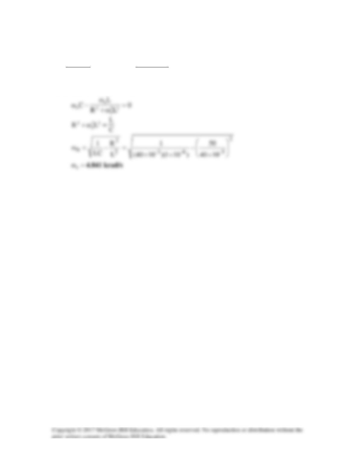
Solution 14.40
(a)
s/krad810x)8690(2)ff(2B
3
1212
π=−π=−π=ω−ω=
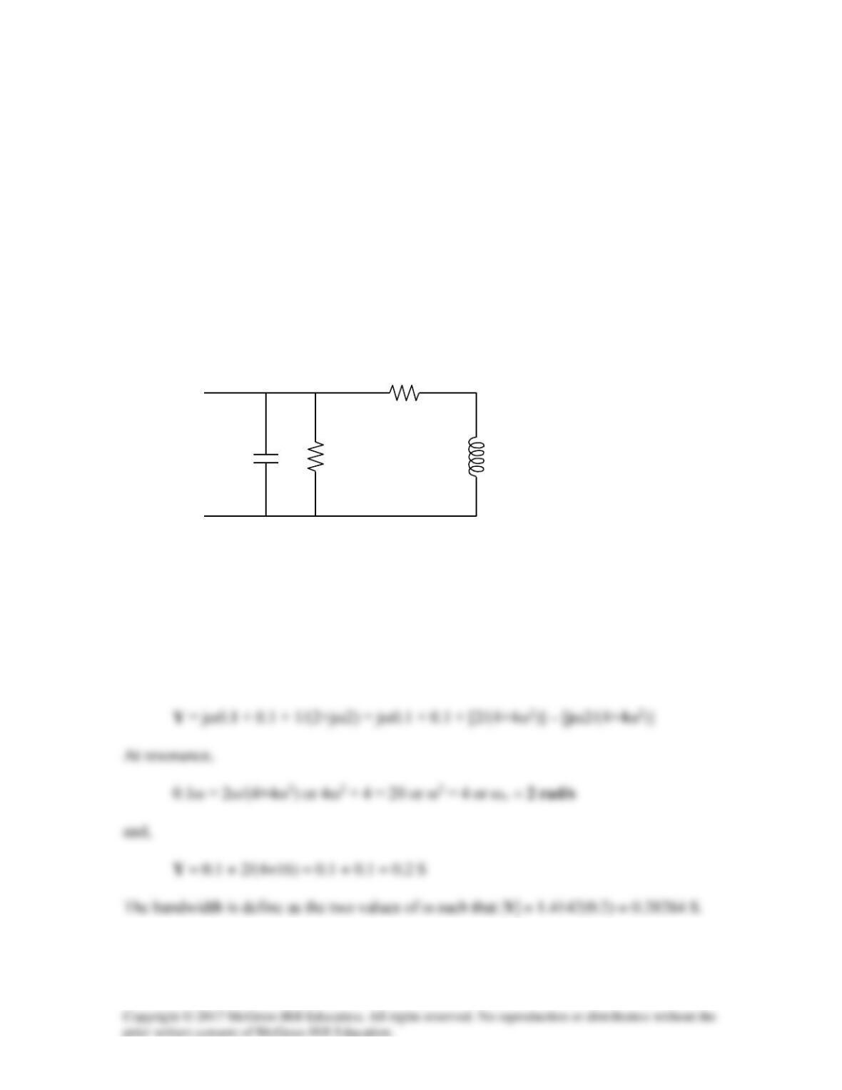
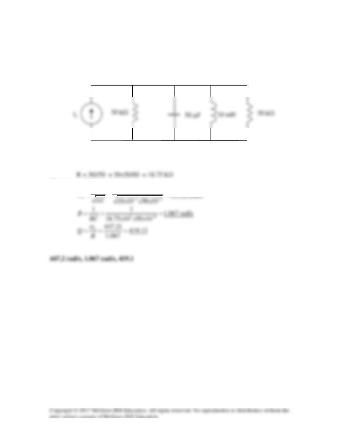
Solution 14.41
Using Fig. 14.80, design a problem to help other students to better understand the quality
factor, the resonant frequency, and bandwidth of an RLC circuit.
Although there are many ways to solve this problem, this is an example based on the
same kind of problem asked in Example 14.9.
Problem
For the circuits in Fig. 14.80, find the resonant frequency
ω
0, the quality factor Q, and the
bandwidth B. Let C = 0.1 F, R1 = 10 Ω, R2 = 2 Ω, and L = 2 H.
Figure 14.80
For Prob. 14.41.
Solution
To find ωo, we need to find the input impedance or input admittance and set imaginary
component equal to zero. Finding the input admittance seems to be the easiest approach.
I do not know about you, but I sure would not want to solve this analytically. So how
about using MATLAB or excel to solve for the two values of ω?
R2
R1
C
L
Solution 14.42
(a) This is a series RLC circuit.
Ω=+= 862R
,
H1L =
,
F4.0C =
(b) This is a parallel RLC circuit.
F2
63
)6)(3(
F6andF3 µ=
+
→µµ
Solution 14.43
(a)
)LjR(||)Cj1(
in
ω+ω=Z
LjR
Cj
LjR
ω+
ω
ω+
(b)
)Cj1Lj(||R
in ω+ω=Z
At resonance,
0)Im( in =Z
, i.e.
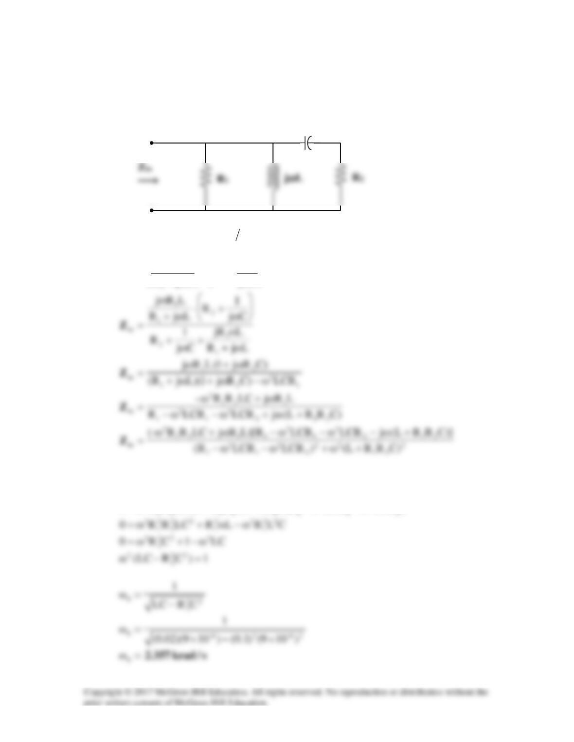
Solution 14.44
Consider the circuit below.
(a)
)Cj1R(||)Lj||R( 21in ω+ω=Z
ω
+
ω+
ω
=Cj
1
R||
LjR
LjR
2
1
in
Z
At resonance,
0)Im(
in
=Z
, i.e.
)LCRLCRR(LR)CRRL(LCRR0 2
2
2
3ω−ω−ω++ω=
1/jωC
(b) At
s/krad357.2
0=ω=ω
,
14.47j)1020)(10357.2(jLj -33=××=ω
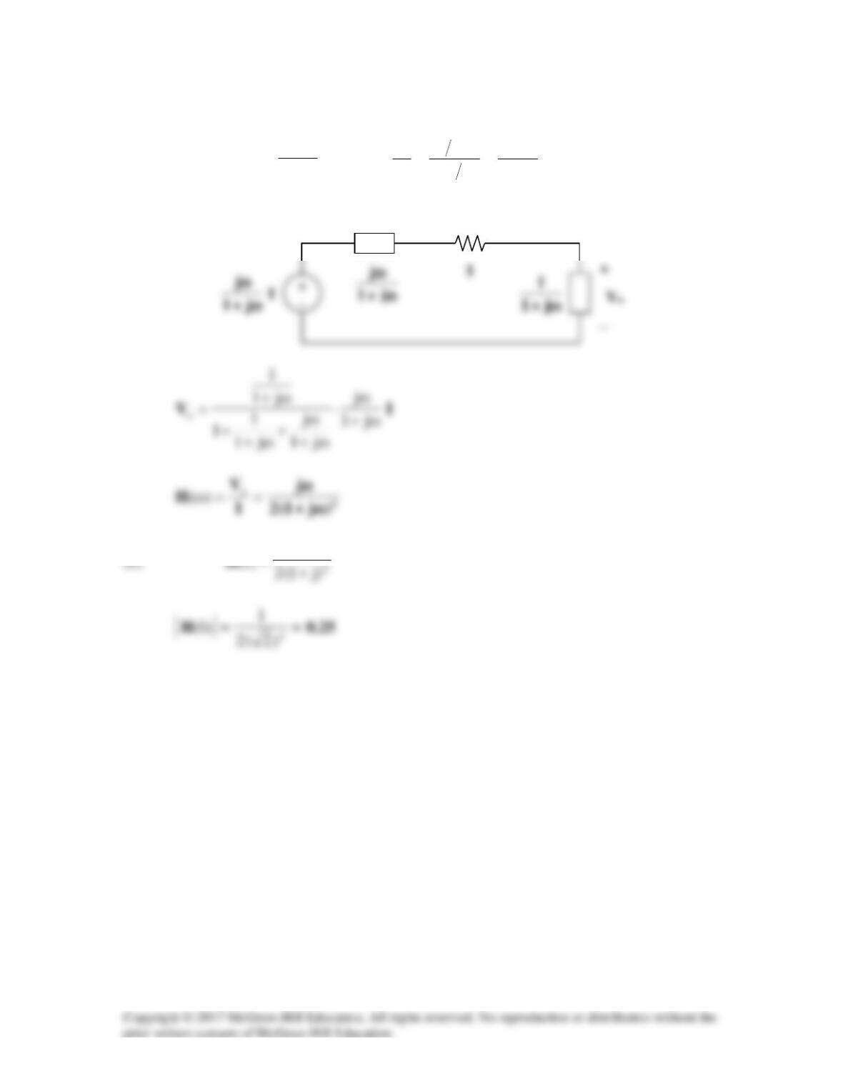
Solution 14.45
Convert the voltage source to a current source as shown below.
This is a parallel resonant circuit.
11
Solution 14.46
(a)
ω+
ω
=ω j1
j
j||1
,
ω+
=
ω+
ω
=
ωj1
1
j11
j1
j
1
||1
Transform the current source gives the circuit below.
1
Solution 14.47
RLj1
1
LjR
R
)(
i
o
ω+
=
ω+
==ω V
V
H
At the corner frequency,
2
1
)(H c=ω
, i.e.
Hence,
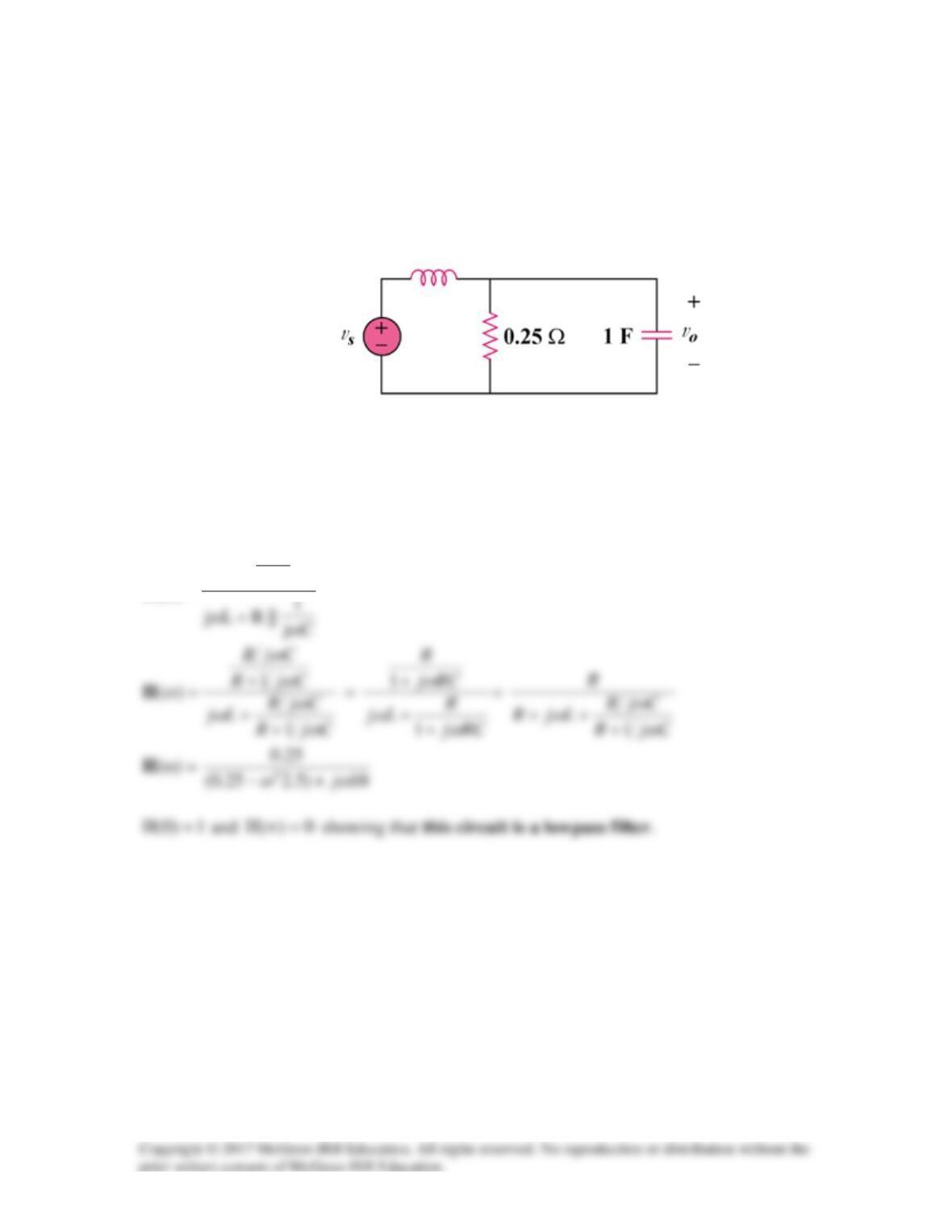
Solution 14.48
Find the transfer function Vo/Vs of the circuit in Fig. 14.86. Show that the circuit is a
lowpass filter.
Figure 14.86
For Prob. 14.48.
Solution
Cj
1
||R
)(
ω
=ωH
10 H
Solution 14.49
Design a problem to help other students to better understand lowpass filters described by
transfer functions.
Although there are many ways to solve this problem, this is an example based on the
same kind of problem asked in the third edition.
Problem
Determine the cutoff frequency of the lowpass filter described by
4
H( ) 2 10j
ωω
=+
Find the gain in dB and phase of H(
ω
) at
ω
= 2 rad/s.
Solution
At dc,
2
4
)0(H ==
.
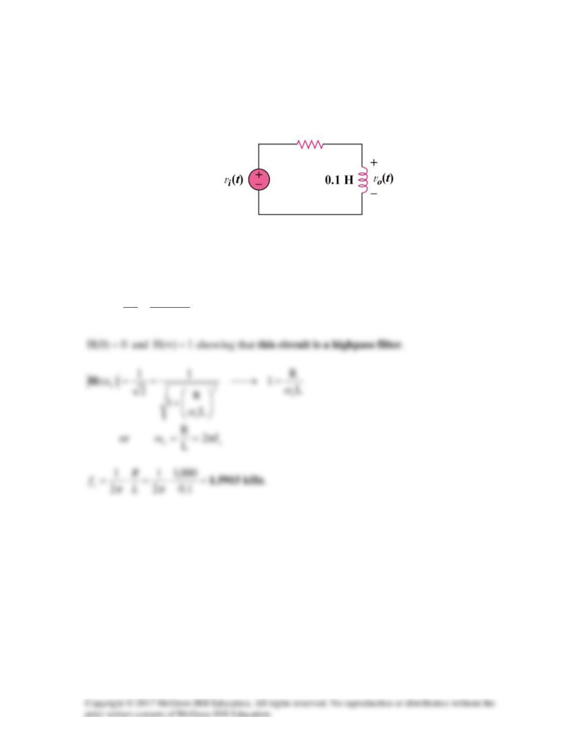
Solution 14.50
Determine what type of filter is in Fig. 14.87. Calculate the corner frequency fc.
Figure 14.87
For Prob. 14.50.
Solution
LjR
Lj
)(
i
o
ω+
ω
==ω V
V
H
1 kΩ
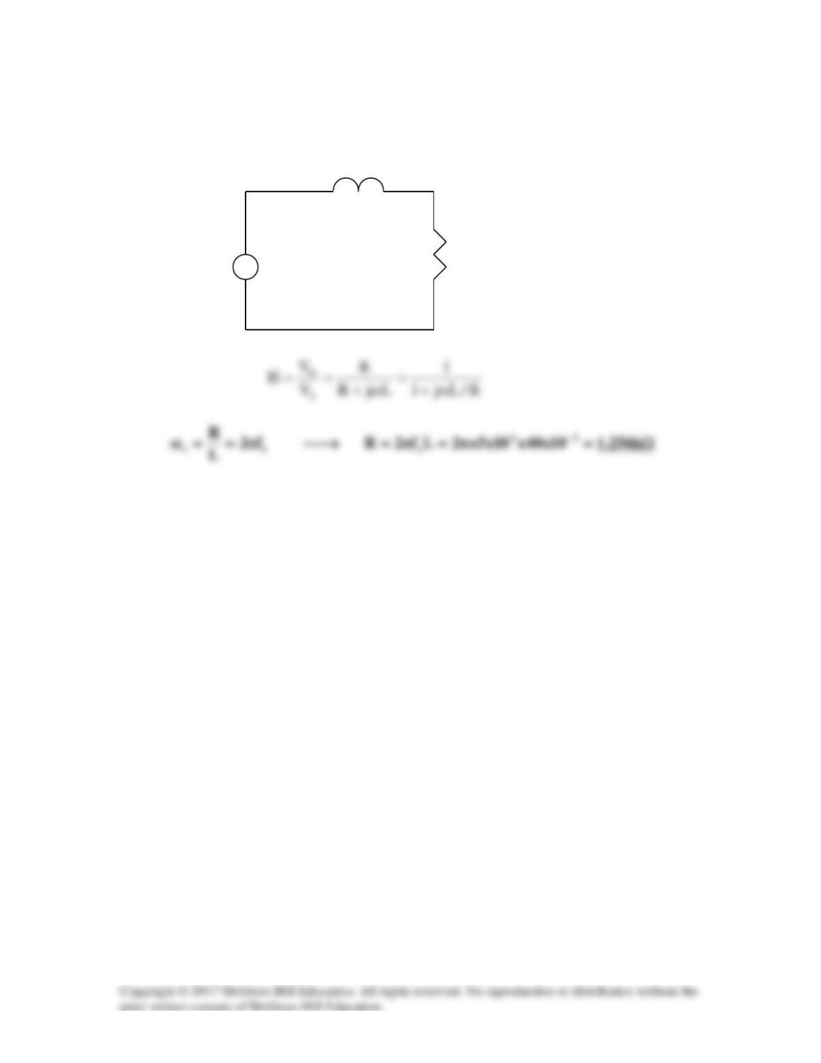
Solution 14.51
The lowpass RL filter is shown below.
L
+ +
vs R vo
–
–
Solution 14.52
Design a problem to help other students to better understand passive highpass filters.
Although there are many ways to solve this problem, this is an example based on the
same kind of problem asked in the third edition.
Problem
In a highpass RL filter with a cutoff frequency of 100 kHz, L = 40 mH. Find R.
Solution
Solution 14.53
3
11 1020f2 ×π=π=ω
3
22 1022f2 ×π=π=ω
Solution 14.54
We start with a series RLC circuit and the use the equations related to the circuit and the
values for a bandstop filter.
Solution 14.55
s/krad10
)104.0)(1025(
1
LC
1
63
o=
××
==ω −−
Solution 14.56
(a) From Eq. 14.54,
LC
1
L
R
ss
L
R
s
LCssRC1
sRC
sC
1
sLR
R
)s(
2
2++
=
++
=
++
=H