Solution 5.19
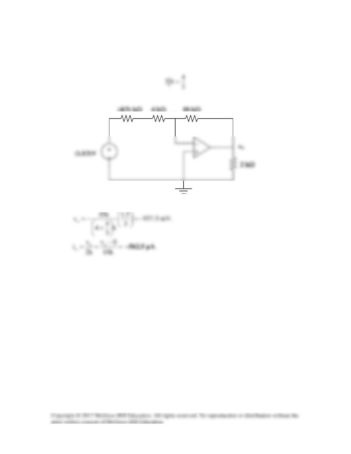
We convert the current source and back to a voltage source.
4 kΩ
10 kΩ
(4/3) kΩ
0V
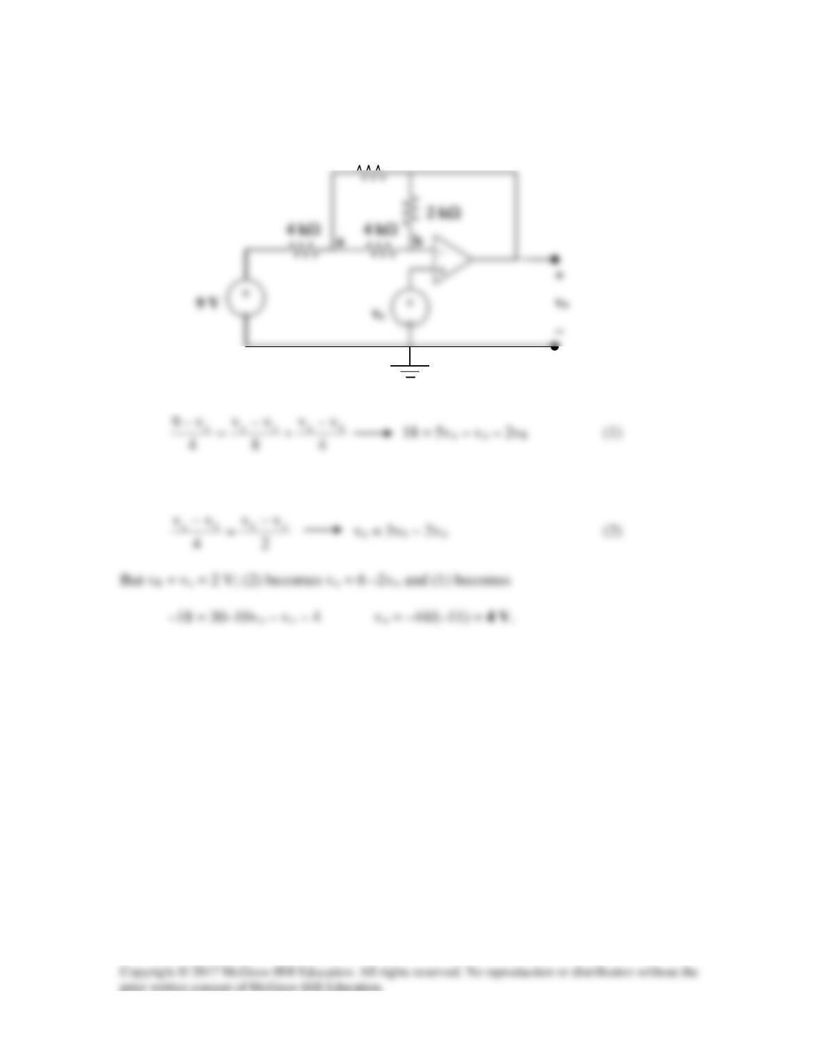
Solution 5.20
4 kΩ
4 kΩ
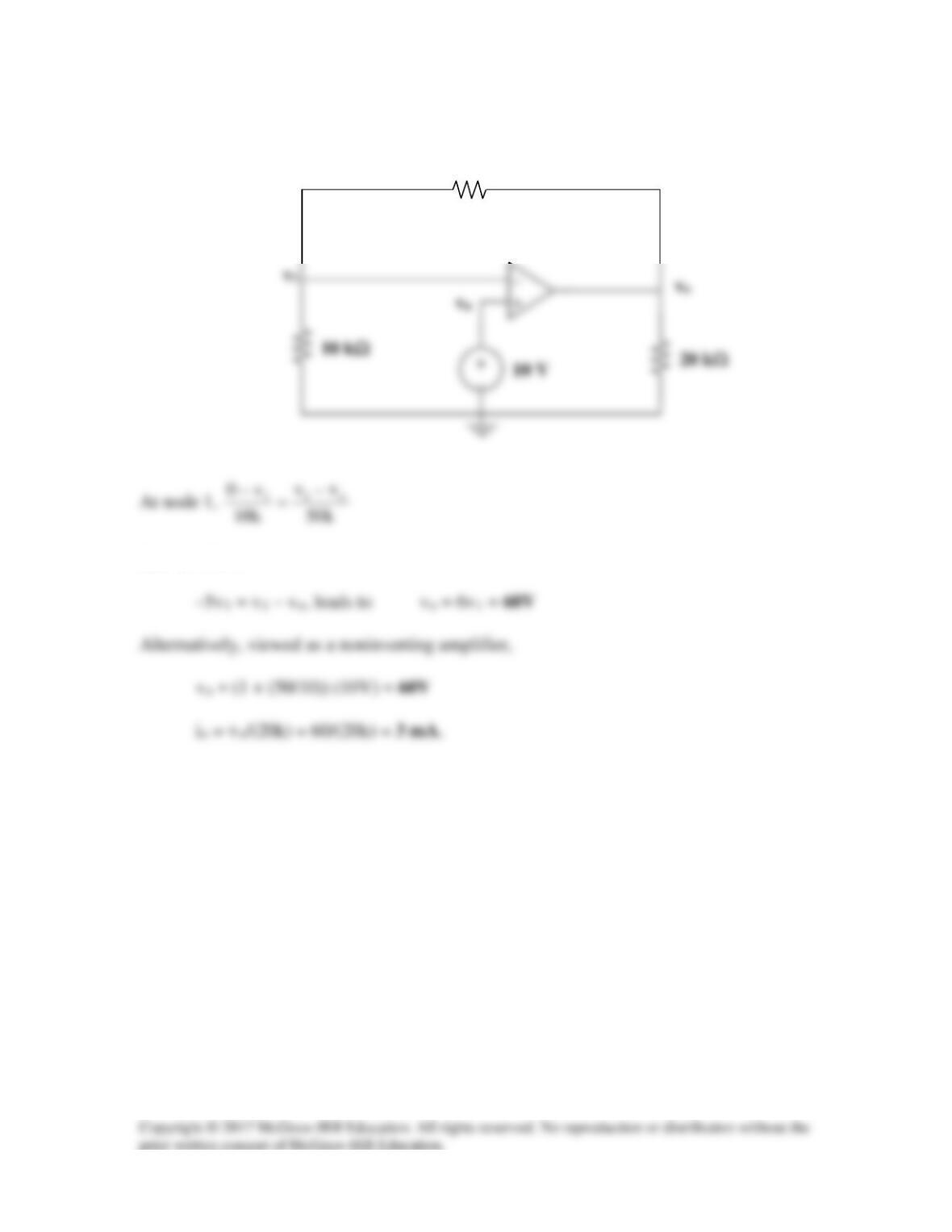
At node a,
At node b,
8 kΩ
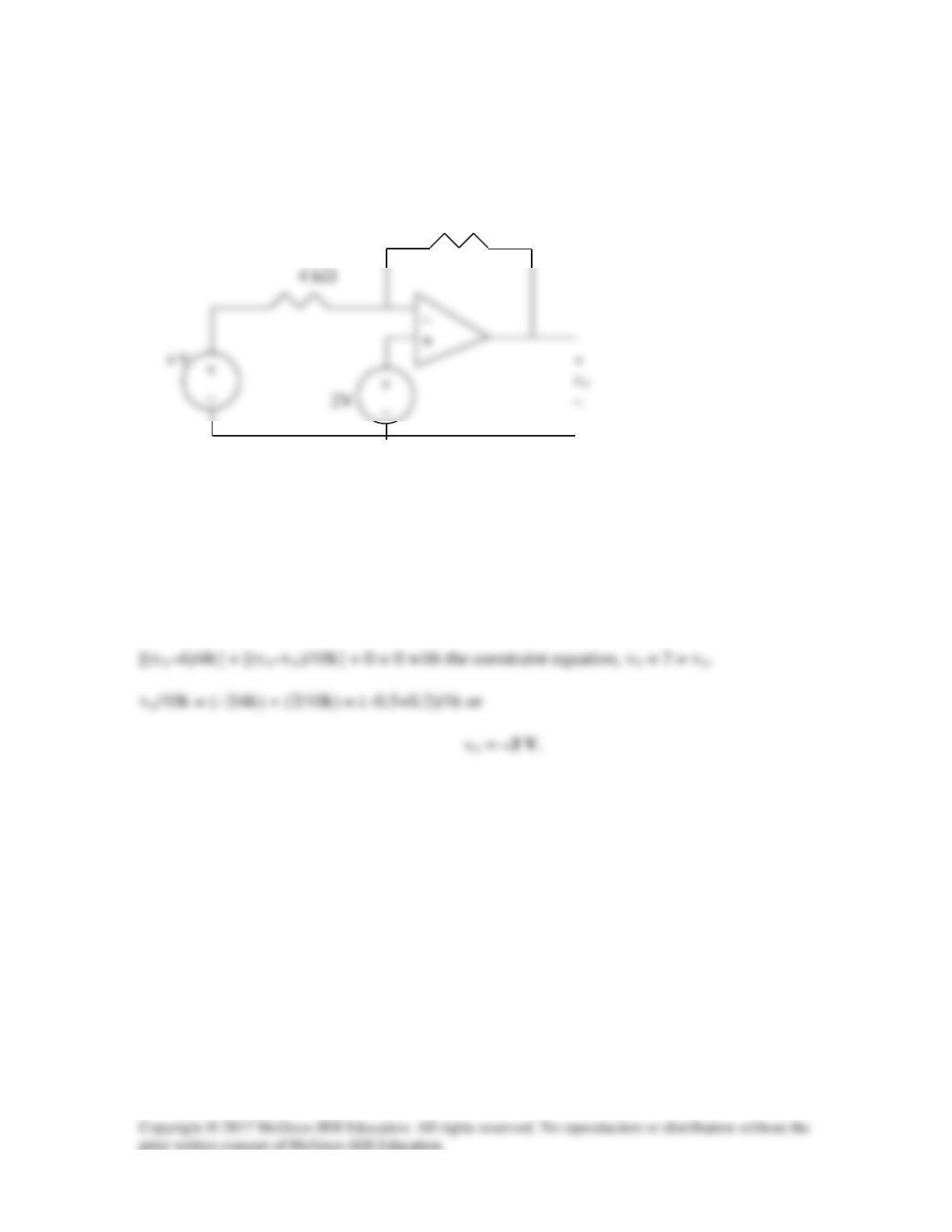
Solution 5.21
Calculate vo in the op amp circuit of Fig. 5.60.
10 kΩ
Figure 5.60
For Prob. 5.21.
Solution
Let the voltage at the inverting input of the op amp be va and at the noninverting input vb.
This leads to,
Solution 5.22
Solution 5.23
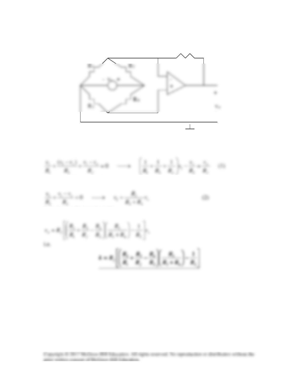
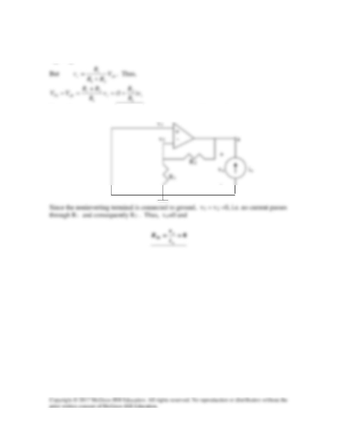
At the inverting terminal, v=0 so that KCL gives
Solution 5.24
v1 Rf
v2 –
We notice that v1 = v2. Applying KCL at node 1 gives
Applying KCL at node 2 gives
Substituting (2) into (1) yields
Solution 5.25
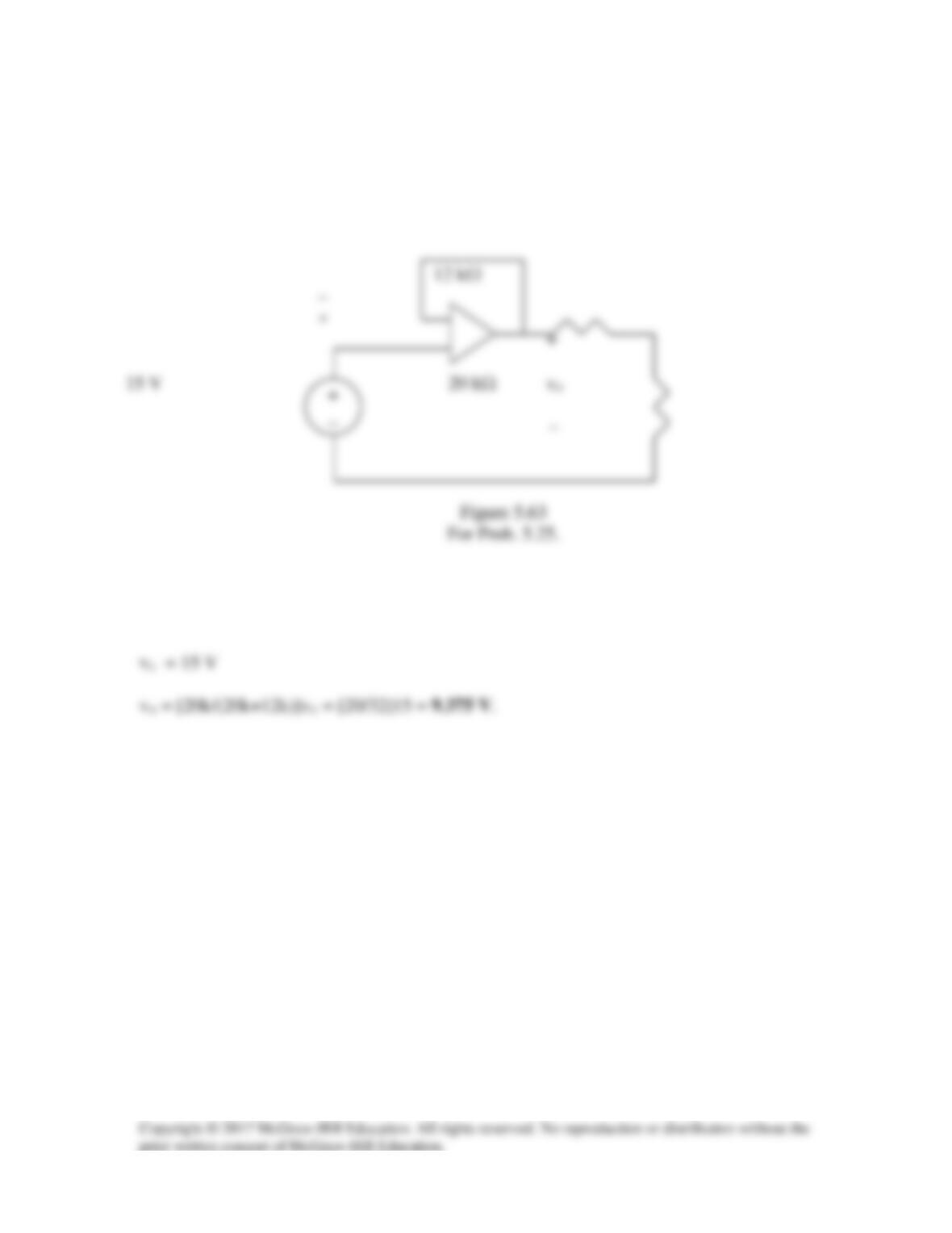
Calculate vo in the op amp circuit of Fig. 5.63.
Solution
This is a voltage follower. If vc is the output of the op amp,
Solution 5.26
Using Fig. 5.64, design a problem to help other students better understand noninverting
Problem
Determine io in the circuit of Fig. 5.64.
Figure 5.64
Solution
+
vb – io
Solution 5.27
This is a voltage follower.
Solution 5.28
But v1 = 10V,
50 kΩ
Solution 5.29
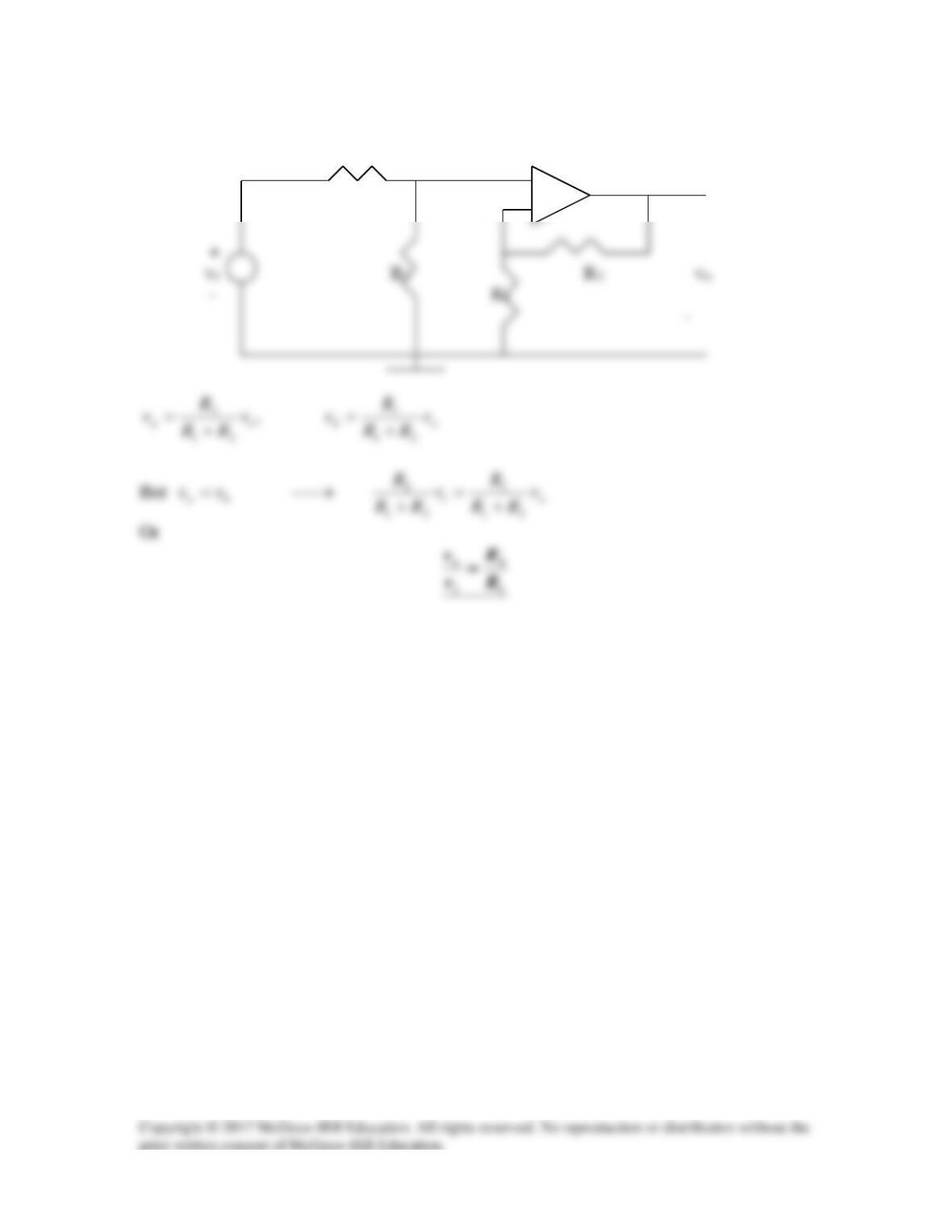
R1 va
+
vb – +
Solution 5.30
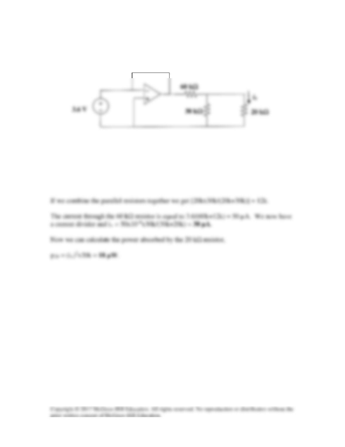
In the circuit shown in Fig. 5.68, find ix and the power absorbed by the 20-kΩ resistor.
Figure 5.68
For Prob. 5.30.
Solution
The op amp is clearly a voltage follower with an output voltage equal to 3.6 V.
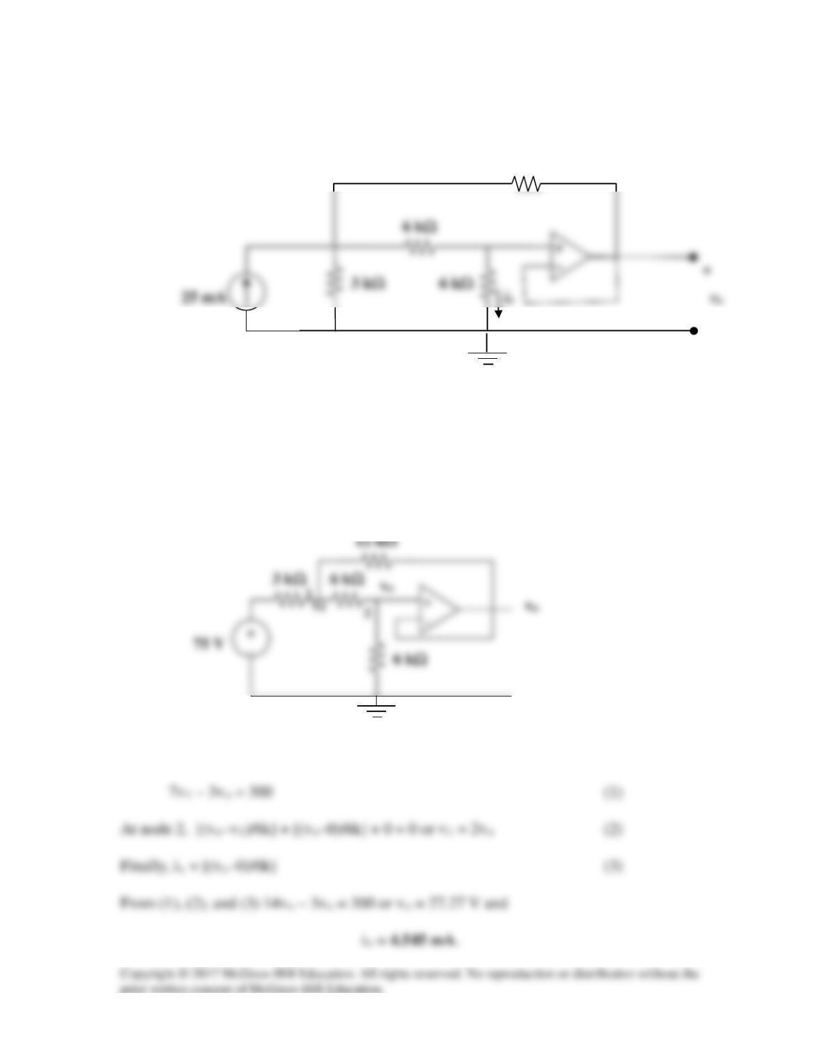
Solution 5.31
For the circuit in Fig. 5.69, find ix.
Figure 5.69
For Prob. 5.31.
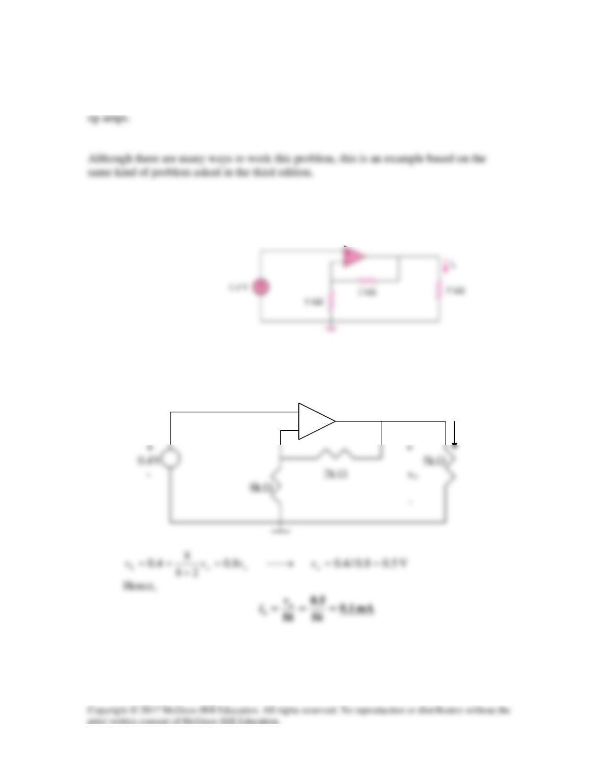
Solution
After converting the current source to a voltage source, the circuit is as shown below:
12 kΩ
At node 1, [(v1–75)/3k] + [(v1–vo)/6k] + [(v1–vo)/12k] = 0 or
12 kΩ
−
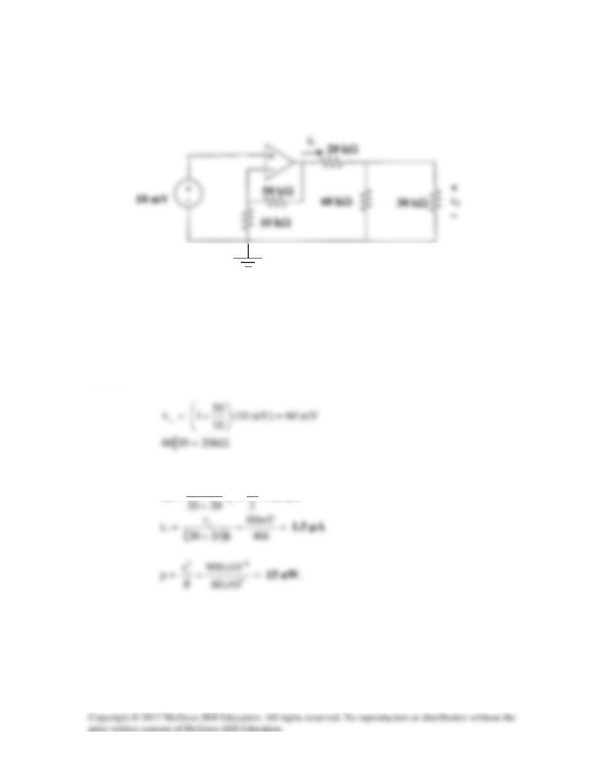
Solution 5.32
Calculate ix and vo in the circuit of Fig. 5.70. Find the power dissipated by the 60-kΩ
resistor.
Figure 5.70
For Prob. 5.32.
Solution
Let
vx = the voltage at the output of the op amp. The given circuit is a non-inverting
amplifier.
By voltage division,
==
20
x
v
v
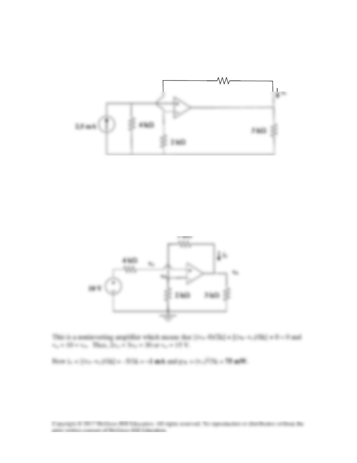
Solution 5.33
Refer to the op amp circuit in Fig. 5.71. Calculate ix and the power absorbed by the 3-kΩ
resistor.
Figure 5.71
For Prob. 5.33.
Solution
After transforming the current source, the current is as shown below:
1 kΩ
Solution 5.34
Combining (1) and (2),
Solution 5.35
Solution 5.36
abTh VV =
To get RTh, apply a current source Io at terminals a-b as shown below.
–
b
Solution 5.37
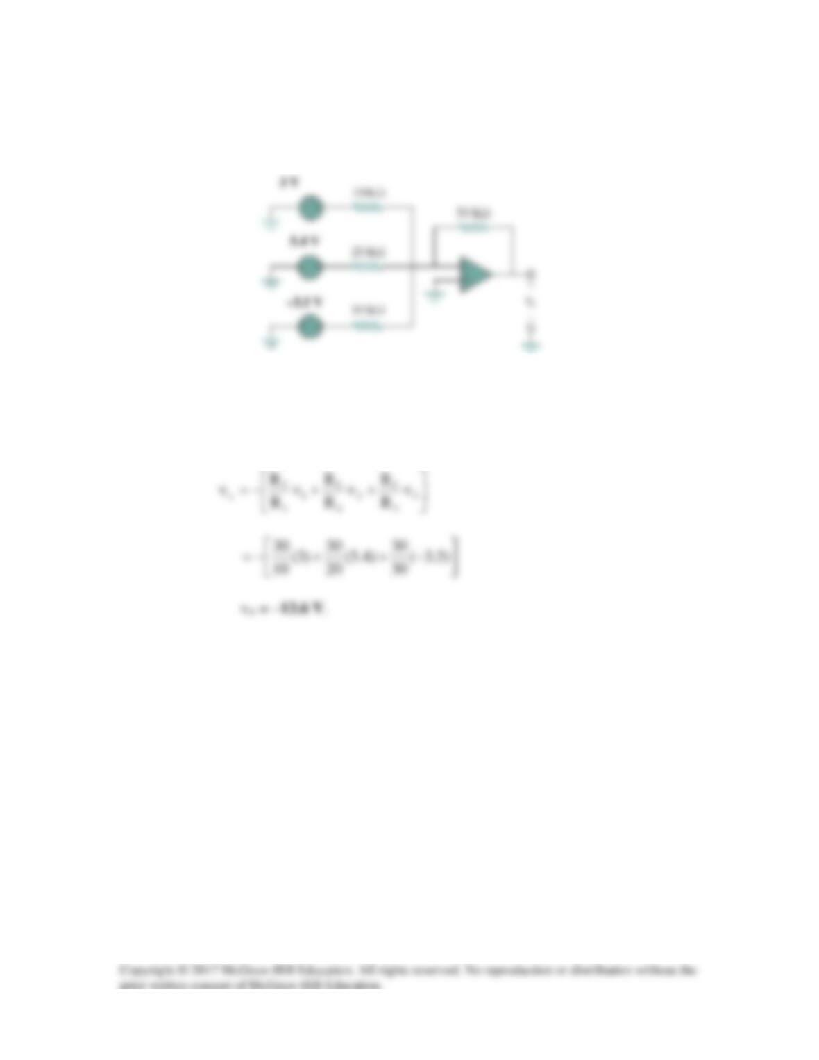
Determine the output of the summing amplifier in Fig. 5.74.
Figure 5.74
For Prob. 5.37.
Solution
Solution 5.38
Using Fig. 5.75, design a problem to help other students better understand summing
Problem
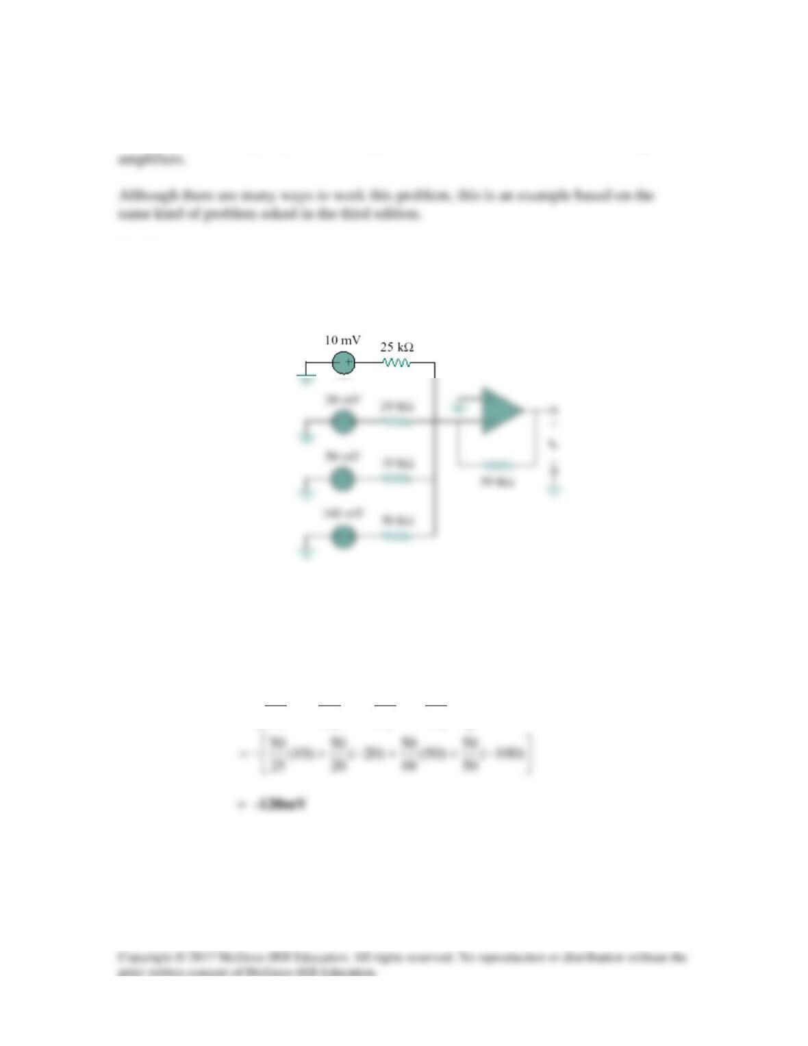
Calculate the output voltage due to the summing amplifier shown in Fig. 5.75.
Figure 5.75
Solution
+++−=
4
4
f
3
3
f
2
2
f
1
1
f
o
v
R
R
v
R
R
v
R
R
v
R
R
v