Solution 4.47
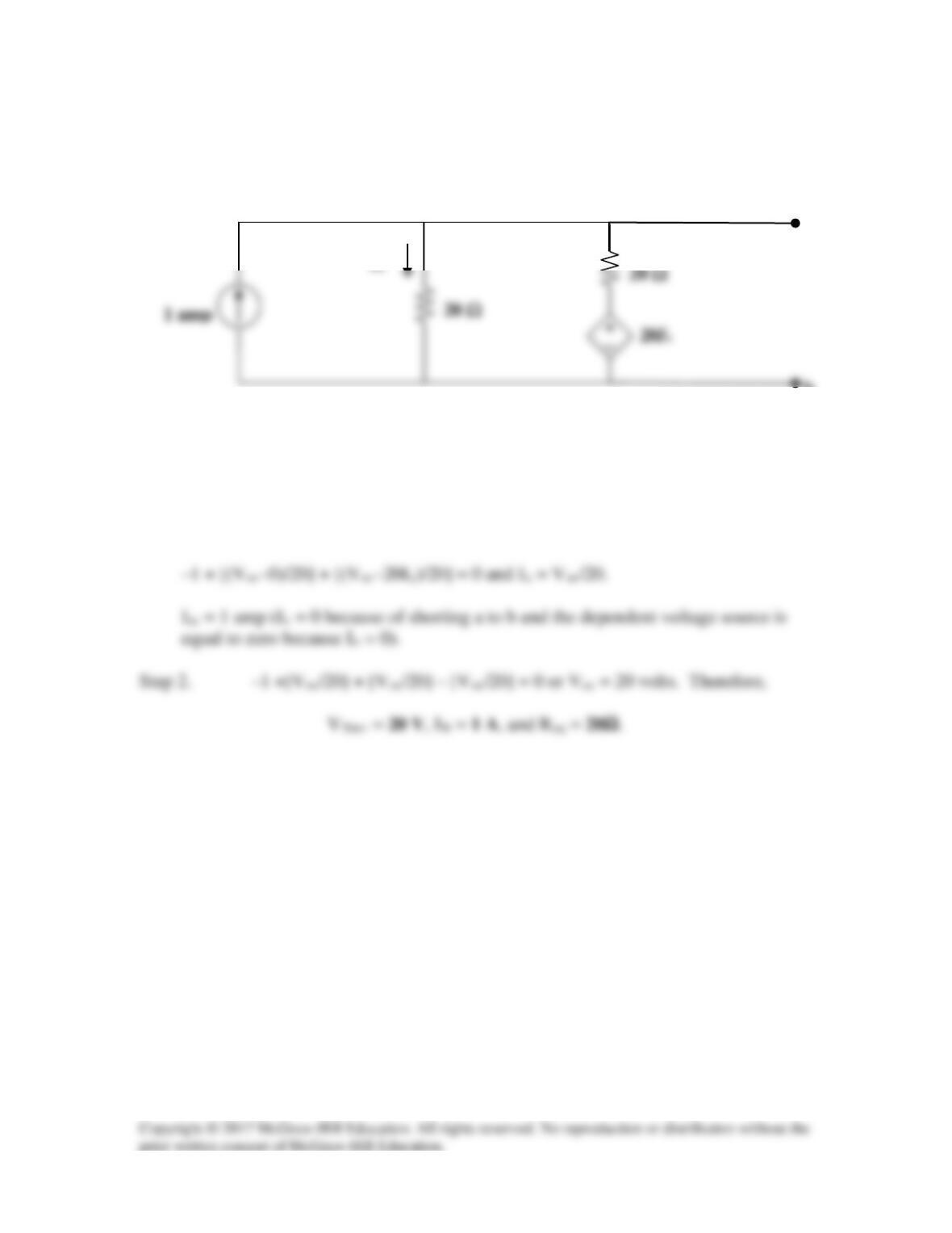
Obtain the Thevenin and Norton equivalent circuits of the circuit in Fig. 4.114 with
respect to terminals a and b.
1 amp
Figure 4.114
For Prob. 4.47.
Solution
Step 1. We note that there is a dependent source which means to best way to
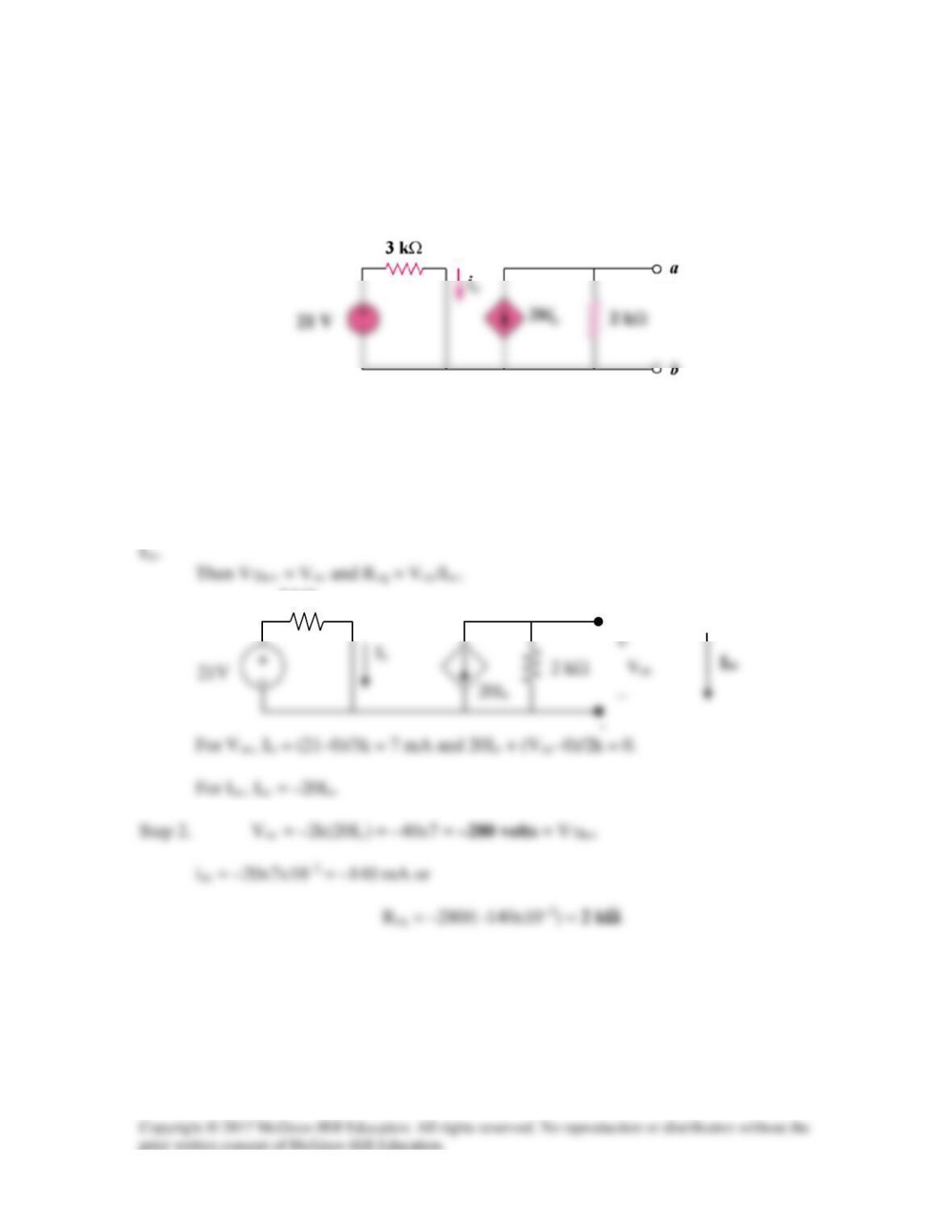
identify the equivalent circuits is to find Voc = VThev and Isc = IN and Req = Voc/Isc.
b
a
Solution 4.48
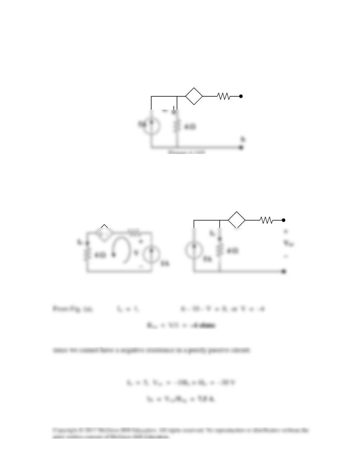
Determine the Norton equivalent at terminals a–b for the circuit in Fig. 4.115.
Figure 4.115
For Prob. 4.48.
Solution
To get RTh, consider the circuit in Fig. (a).
+ −
Note that the negative value of Req indicates that we have an active device in the circuit
To solve for IN we first solve for Voc, consider the circuit in Fig. (b),
(b)
2 Ω
+ −
10I
o
(a)
2 Ω
10Io
2 Ω
+ −
10Io
a
Solution 4.49
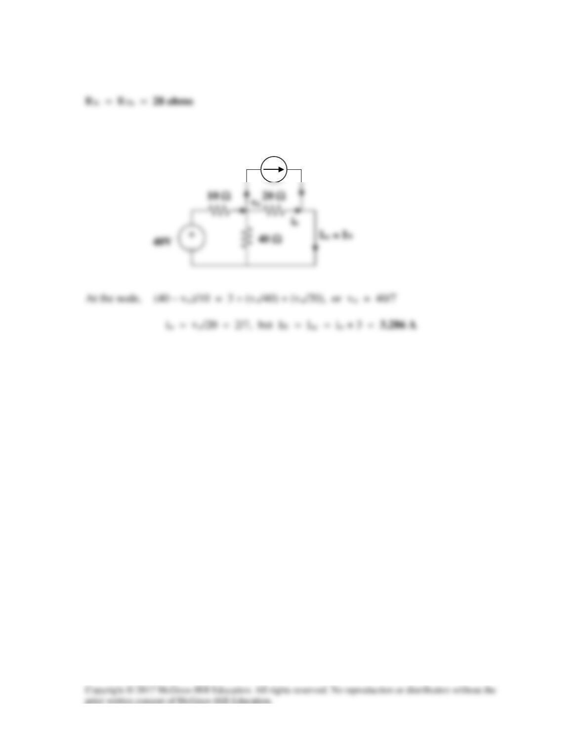
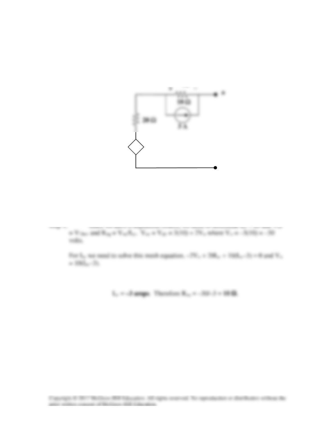
To find IN, consider the circuit below,
3A
Solution 4.50
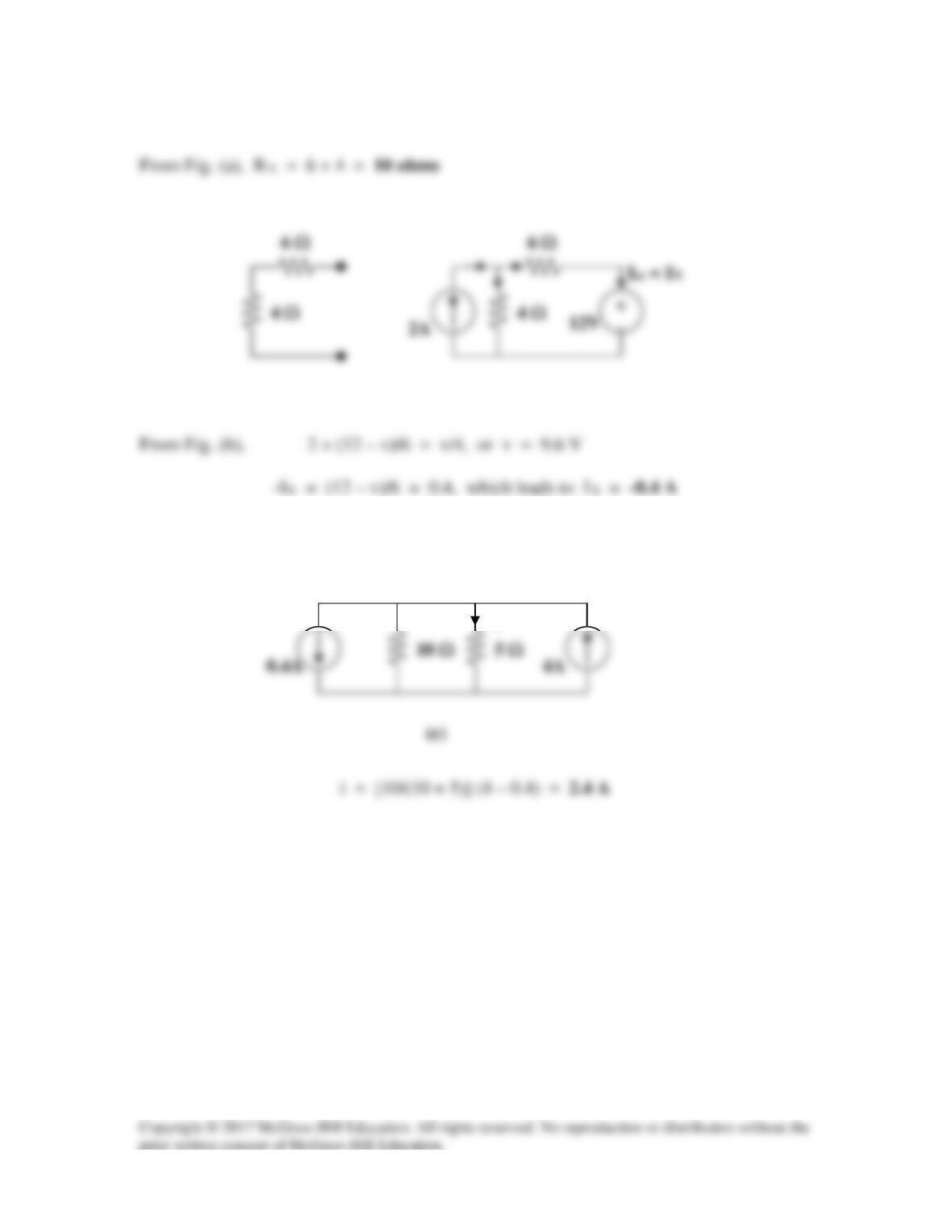
Combining the Norton equivalent with the right-hand side of the original circuit produces
the circuit in Fig. (c).
(a)
(b)
i
Solution 4.51
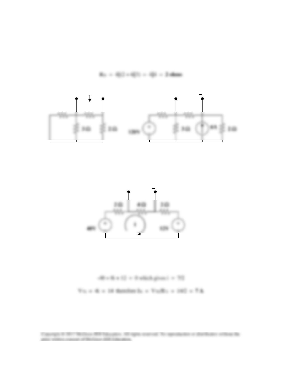
(a) From the circuit in Fig. (a),
For IN or VTh, consider the circuit in Fig. (b). After some source transformations, the
circuit becomes that shown in Fig. (c).
2 Ω
4 Ω
2 Ω
Applying KVL to the circuit in Fig. (c),
6 Ω
(a)
4 Ω
RTh
6 Ω
(b)
4 Ω
VTh
+
(c)
VTh
+
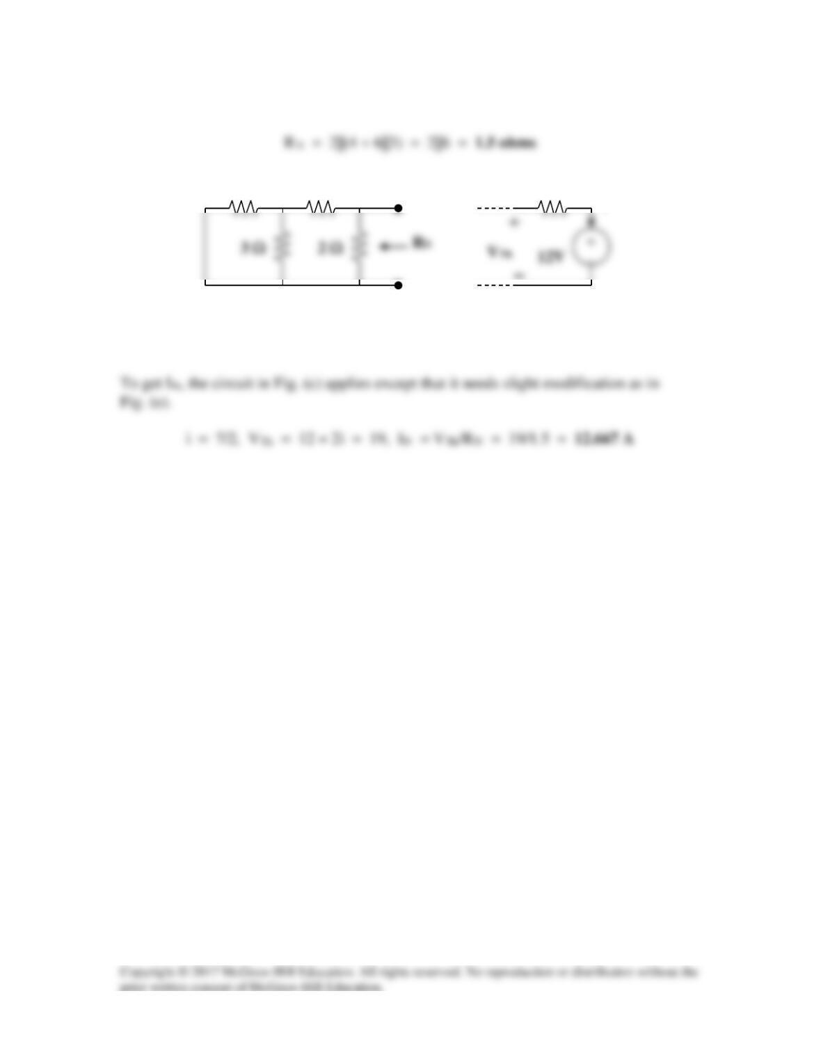
(b) To get RN, consider the circuit in Fig. (d).
6 Ω
(d)
4 Ω
(e)
2 Ω
i
Solution 4.52
For the transistor model in Fig. 4.118, obtain the Thevenin equivalent at terminals a–b.
Figure 4.118
For Prob. 4.52.
Solution
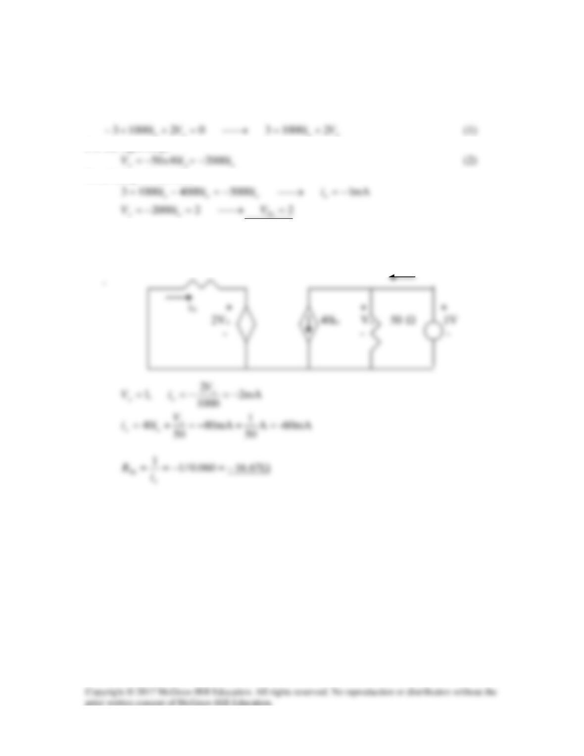
Step 1. To find the Thevenin equivalent for this circuit we need to find Voc and
3 kΩ
Solution 4.53
Find the Norton equivalent at terminals a–b of the circuit in Fig. 4.119.
Figure 4.119
For Prob. 4.53.
Solution
Step 2. Voc = 30 – 60 = –30 volts. –20(Isc–3) +20Isc + 10Isc – 30 = 0 or
b
Vo
+
−
2Vo
Solution 4.54
To find VTh =Vx, consider the left loop.
For the right loop,
Combining (1) and (2),
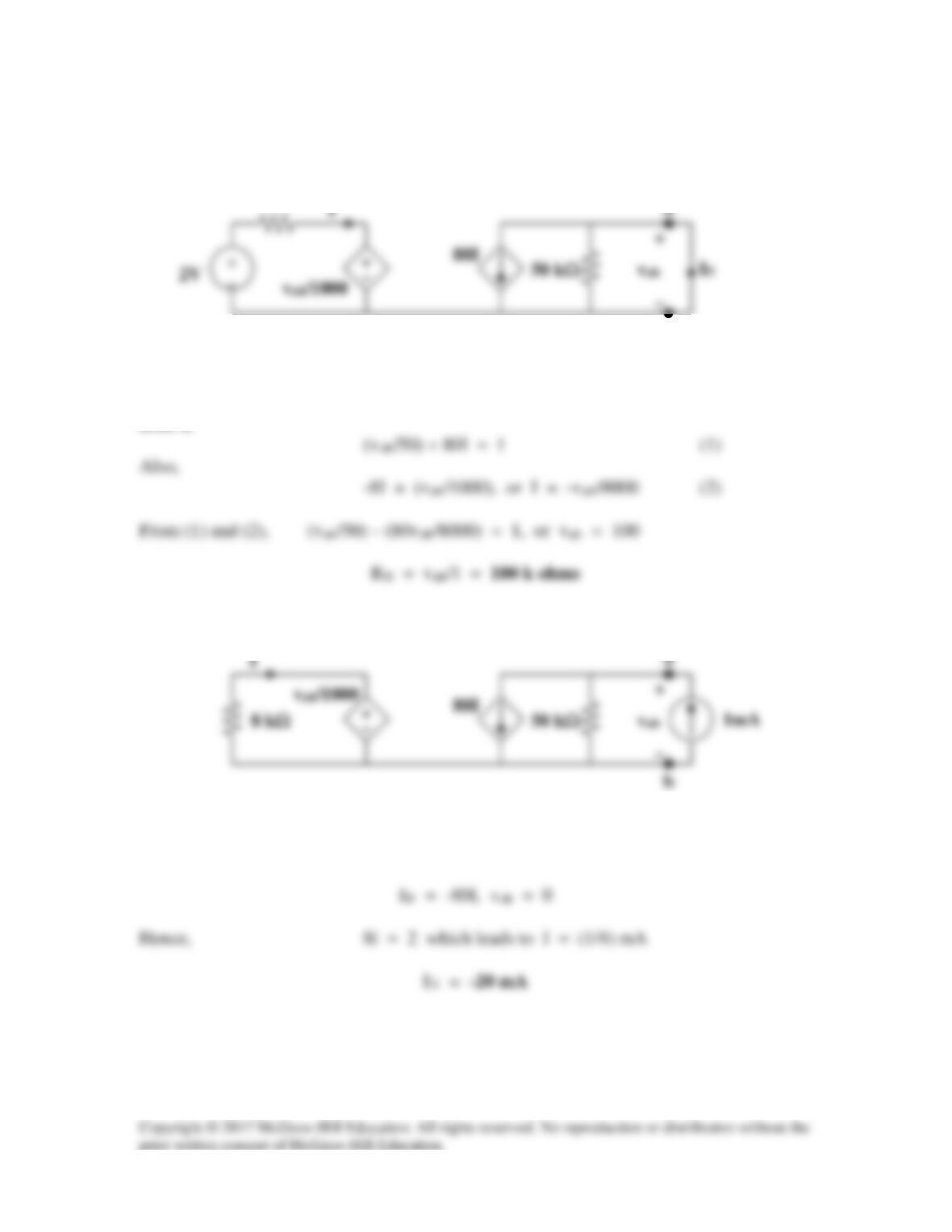
To find RTh, insert a 1–V source at terminals a-b and remove the 3-V independent source,
as shown below.
1 k
Ω
ix
Ω
Solution 4.55
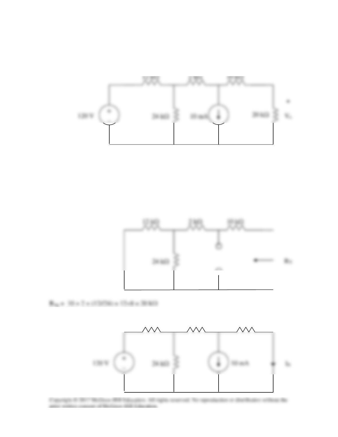
To get RN, apply a 1 mA source at the terminals a and b as shown in Fig. (a).
We assume all resistances are in k ohms, all currents in mA, and all voltages in volts. At
node a,
To get IN, consider the circuit in Fig. (b).
b
1mA
Since the 50-k ohm resistor is shorted,
(b)
b
8 kΩ
(a)
Solution 4.56
Use Norton’s theorem to find Vo in the circuit of Fig. 4.122.
Figure 4.122
For Prob. 4.56.
Solution
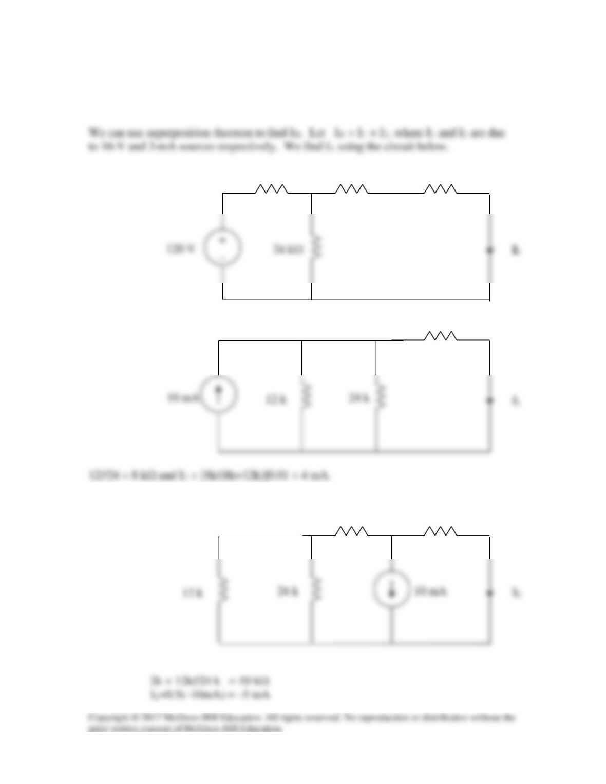
We remove the 20 kΩ resistor temporarily and find the Norton equivalent across its
terminals. Req is obtained from the circuit below.
IN is obtained from the circuit below.
10 k
12 k
2 k
_
Using source transformation, we obtain the circuit below.
12 k
24 k
To find I2, consider the circuit below.
12 k
24 k
10 k
12 k
2 k
12 k
10 k
2 k
IN = 4–5 = –1 mA
The Norton equivalent with the 20 kΩ resistor is shown below
+
a
Solution 4.57
To find RTh, remove the 50V source and insert a 1-V source at a – b, as shown in Fig. (a).
2 Ω
We apply nodal analysis. At node A,
To get VTh, consider the circuit in Fig. (b).
From (3) and (4),
v2 = VTh = 166.67 V
v1
2 Ω
a
3 Ω
v2
(a)
b
Solution 4.58
This problem does not have a solution as it was originally stated. The reason for this is
Writing the node equation at node vo,
ib + βib = vo/R2 = (1 + β)ib
vo
R1
β ib
i
b
Solution 4.59
To find VTh, consider the circuit below.
i1
i2
Solution 4.60
The circuit can be reduced by source transformations.
−
12 V
−
18 V
−
10 V
5 Ω
2A
+
−
10 V
5 Ω
2A
Norton Equivalent Circuit
Thevenin Equivalent Circuit
Solution 4.61
To find RTh, consider the circuit in Fig. (a).
To get VTh, we apply mesh analysis to the circuit in Fig. (d).
a
a
Solution continued on the next page…
(a)
b
2 Ω
(b)
b
a
2 Ω
(c)
b
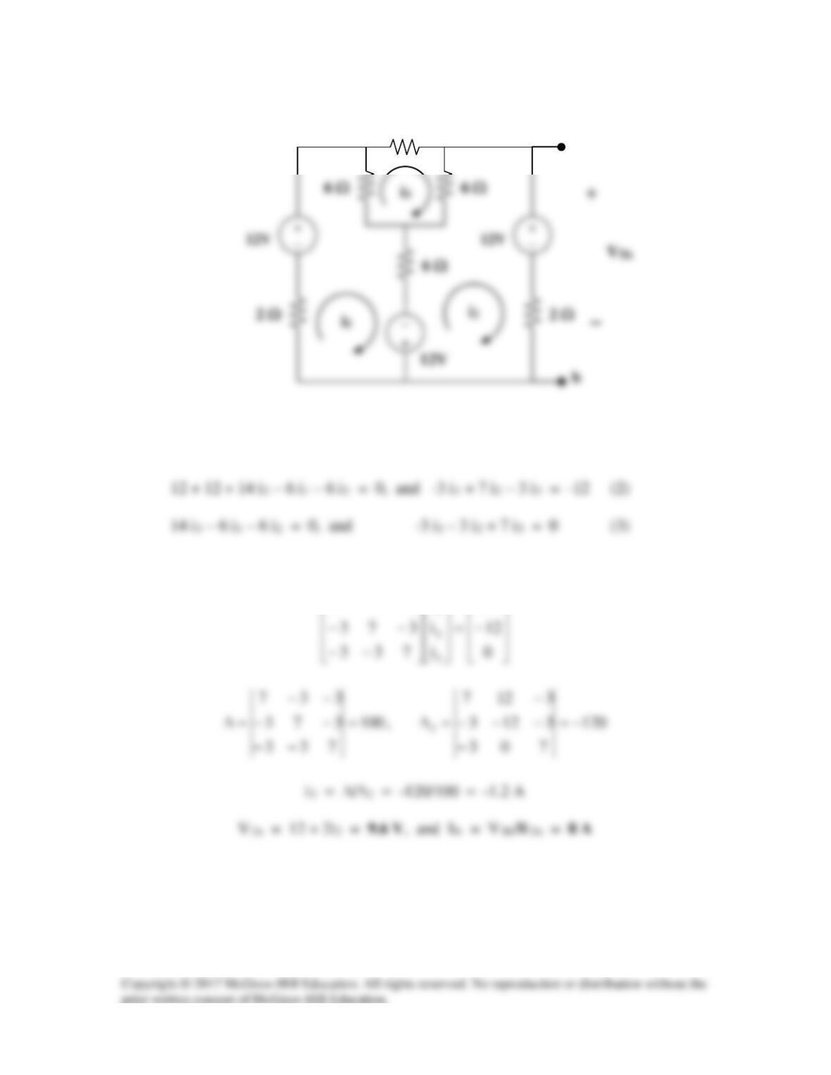
-12 – 12 + 14i1 – 6i2 – 6i3 = 0, and 7 i1 – 3 i2 – 3i3 = 12 (1)
This leads to the following matrix form for (1), (2) and (3),
−−
12
i
337
1
(d)
a
2 Ω
Solution 4.62
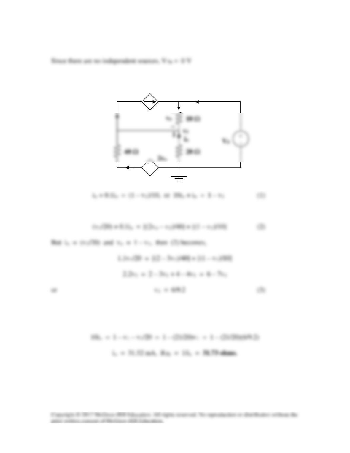
To obtain RTh, consider the circuit below.
io
1
At node 2,
At node 1,
From (1) and (3),
10ix + v1/20 = 1 – v1
+
+
−
ix
0.1io
2