Solution 16.74
Design a problem to help other students to better understand how to find outputs when
given a transfer function and an input.
Although there are many ways to solve this problem, this is an example based on the
same kind of problem asked in the third edition.
Problem
A circuit is known to have its transfer function as
2
3
() 45
s
Hs
ss
+
=++
Find its output when:
(a) the input is a unit step function
(b) the input is 6te-2t u(t).
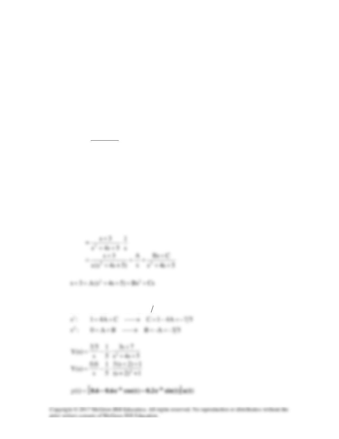
Solution
(a)
)s(X)s(H)s(Y =
Equating coefficients :
0
s
:
53AA53 =→=
2
s
(b)
2
2t–
)2s(
6
)s(Xet6)t(x +
=→=
Equating coefficients :
3
s
:
-ACCA0 =→+=
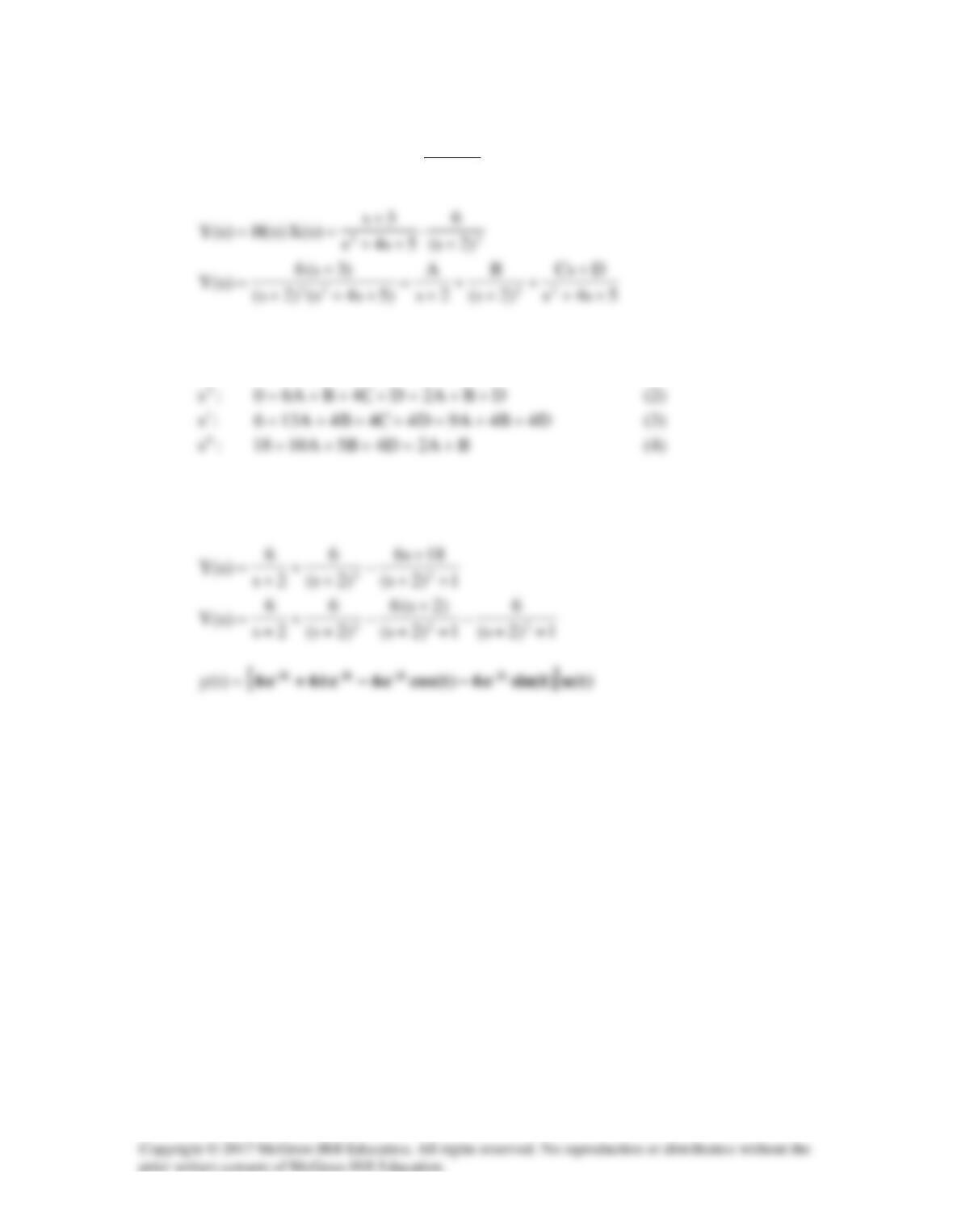
(1)
Solving (1), (2), (3), and (4) gives
6A =
,
6B =
,
6–C =
,
-18D =
Solution 16.75
When a unit step is applied to a system at t = 0, its response is
y(t) =
( ) ( )
( )
32
6 0.75 3cos 4 4.5sin 4 ( )
tt
e e t t ut
−−
+− +
.
What is the transfer function of the system?
Solution
()
Ys
1
Solution 16.76
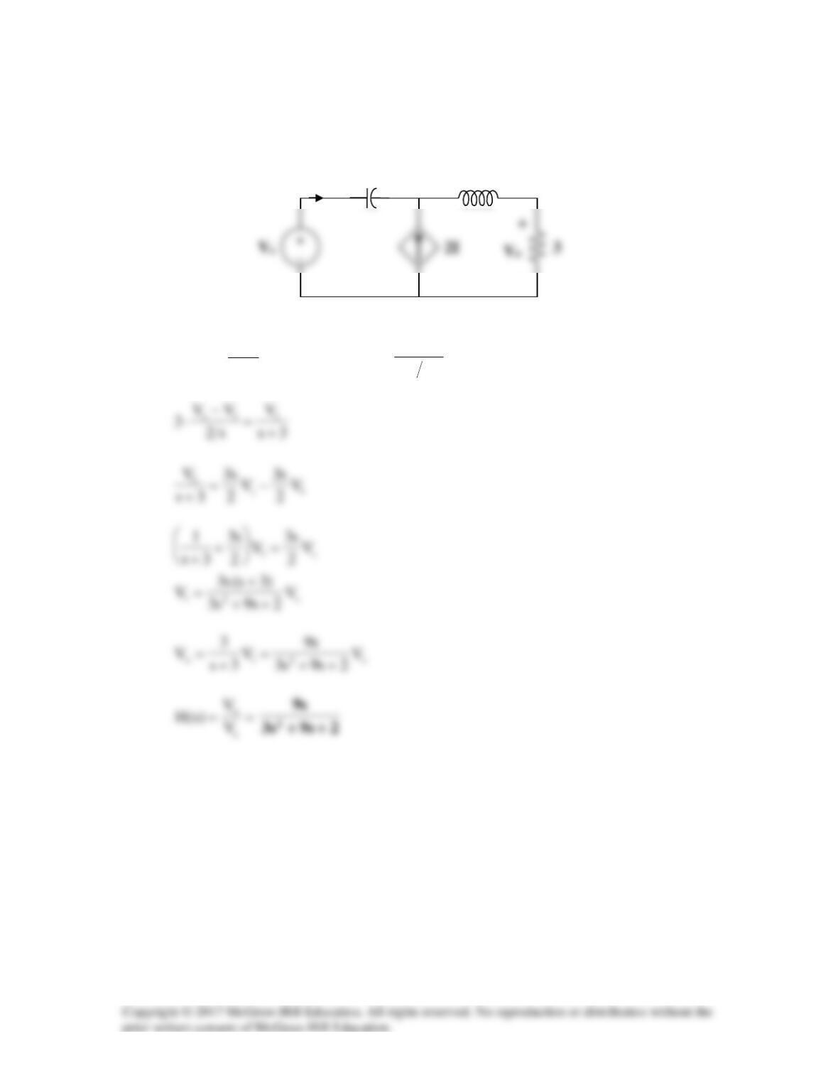
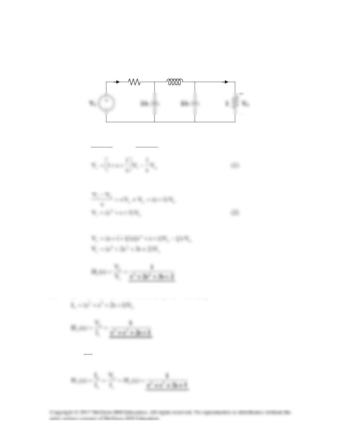
Consider the following circuit.
Using nodal analysis,
s10
V
4
V
2s
VkV ooos +=
+
−
s
2
Vo
+
−
Solution 16.77
Consider the following circuit.
At node 1,
3s
V
II2 1
+
=+
, where
s2
VV
I1s −
=
s
2/s
V
1
I
−
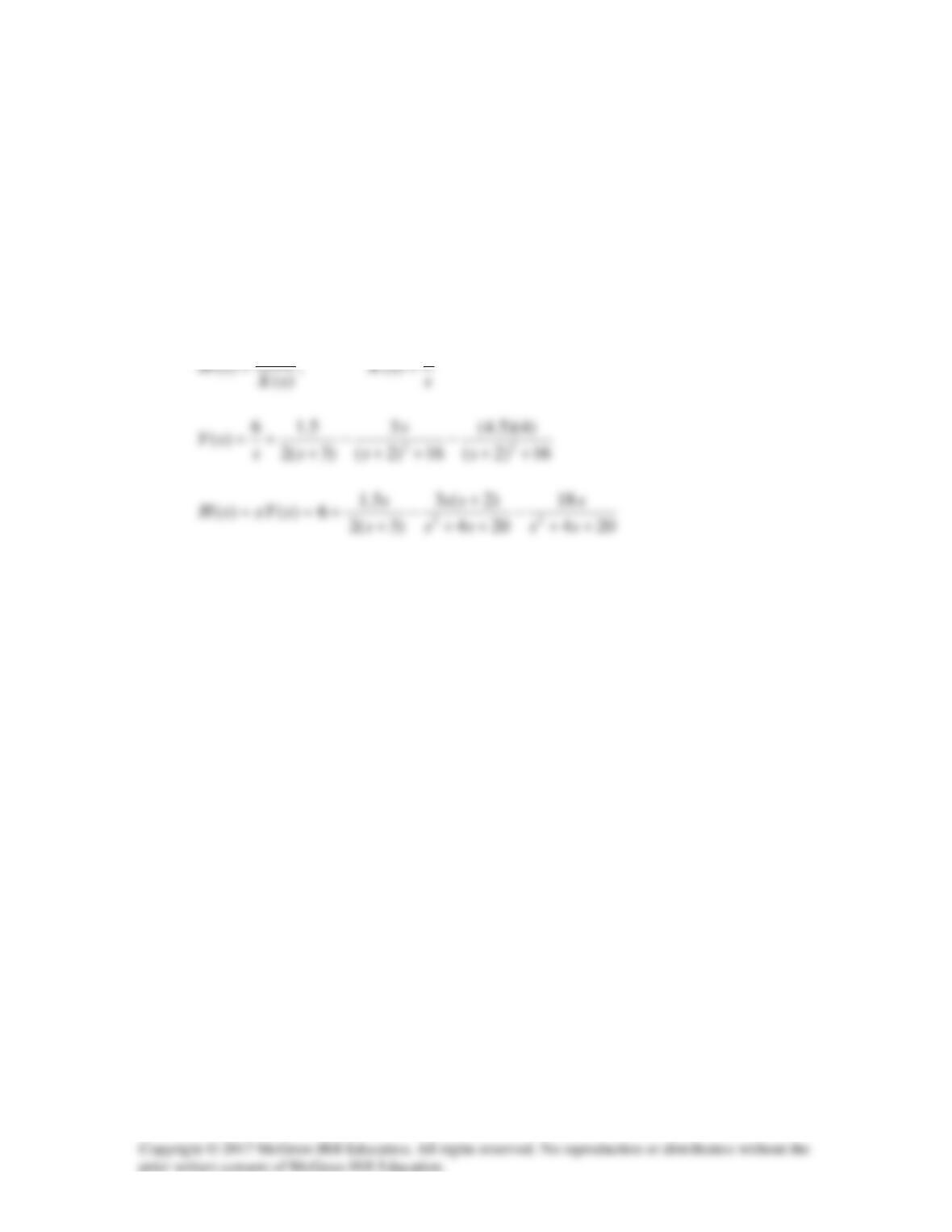
Solution 16.78
The transfer function of a certain circuit is
( )
10 6 12
124
Hs
ss s
=−+
++ +
Find the impulse response of the circuit.
Solution
Solution 16.79
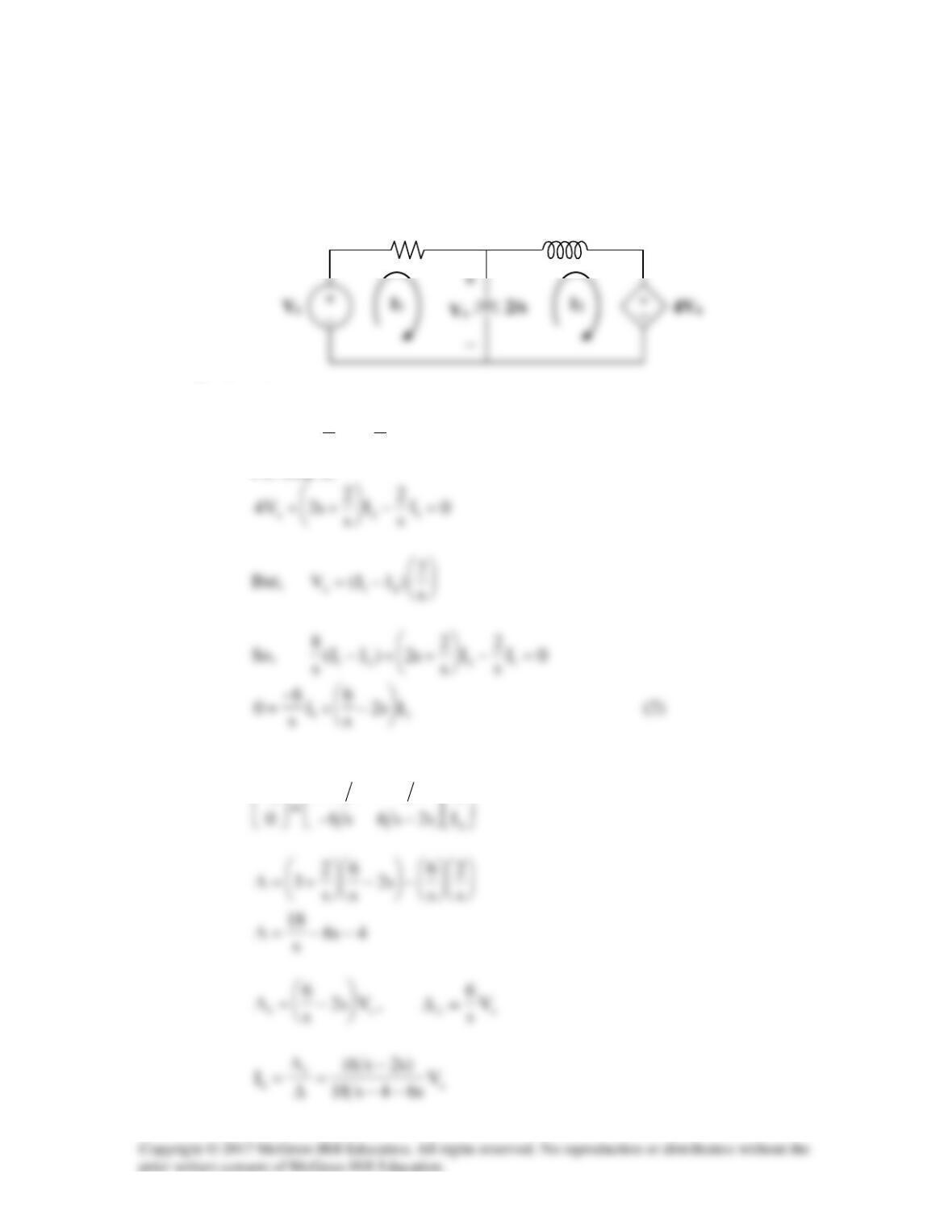
(a) Consider the circuit shown below.
For loop 1,
21s
I
s
2
I
s
2
3V −
+=
(1)
For loop 2,
In matrix form, (1) and (2) become
+
1
s
I
s2–s23
V
2s
3
(b)
∆
∆
=
2
2
I
Solution 16.80
(a) Consider the following circuit.
At node 1,
s
VV
Vs
1
VV
o1
1
1s
−
+=
−
At node o,
Substituting (2) into (1)
(b)
2
23
(c)
1
V
I
o
o
=
s
1
V1
Vo
Io
−
Is
Solution 16.81
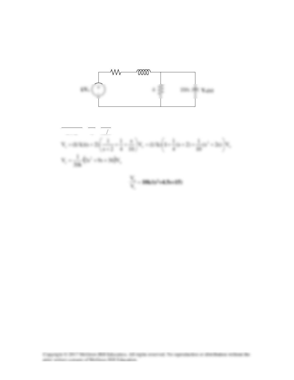
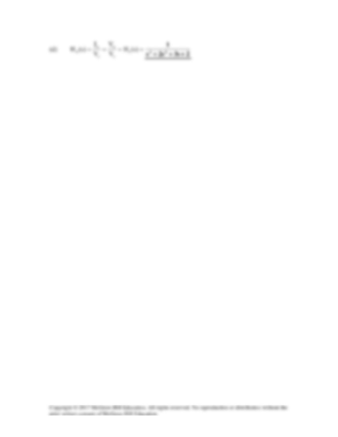
For the op-amp circuit in Fig. 16.99, find the transfer function, T(s) = Io(s)/Vs(s).
Assume all initial conditions are zero.
Figure 16.99
For Prob. 16.81.
Solution
Step 1. Convert the circuit into the s-domain. The write the node equations at the
input to the op amp and solve for T(s).
Step 2. CsVc = –Vs/R or Vc = –Vs/(RCs) and Io = –Vs/(RLCs2) or
C
1/(Cs)
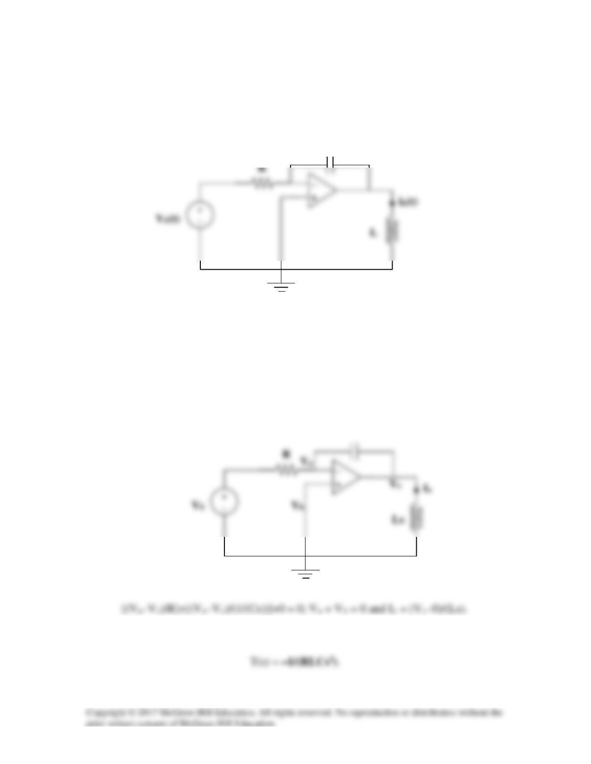
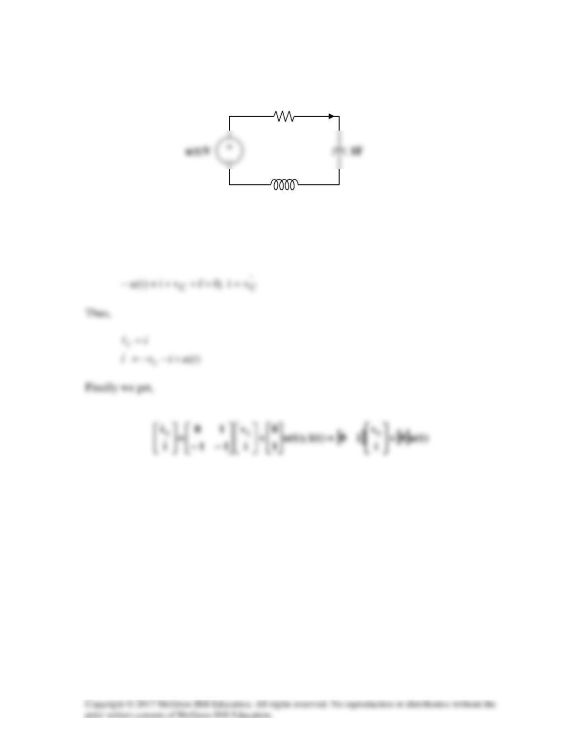
Solution 16.82
Consider the circuit below.
Since no current enters the op amp, o
I
flows through both R and C.
+= sC
1
RI–V
oo
−
+
V
a
V
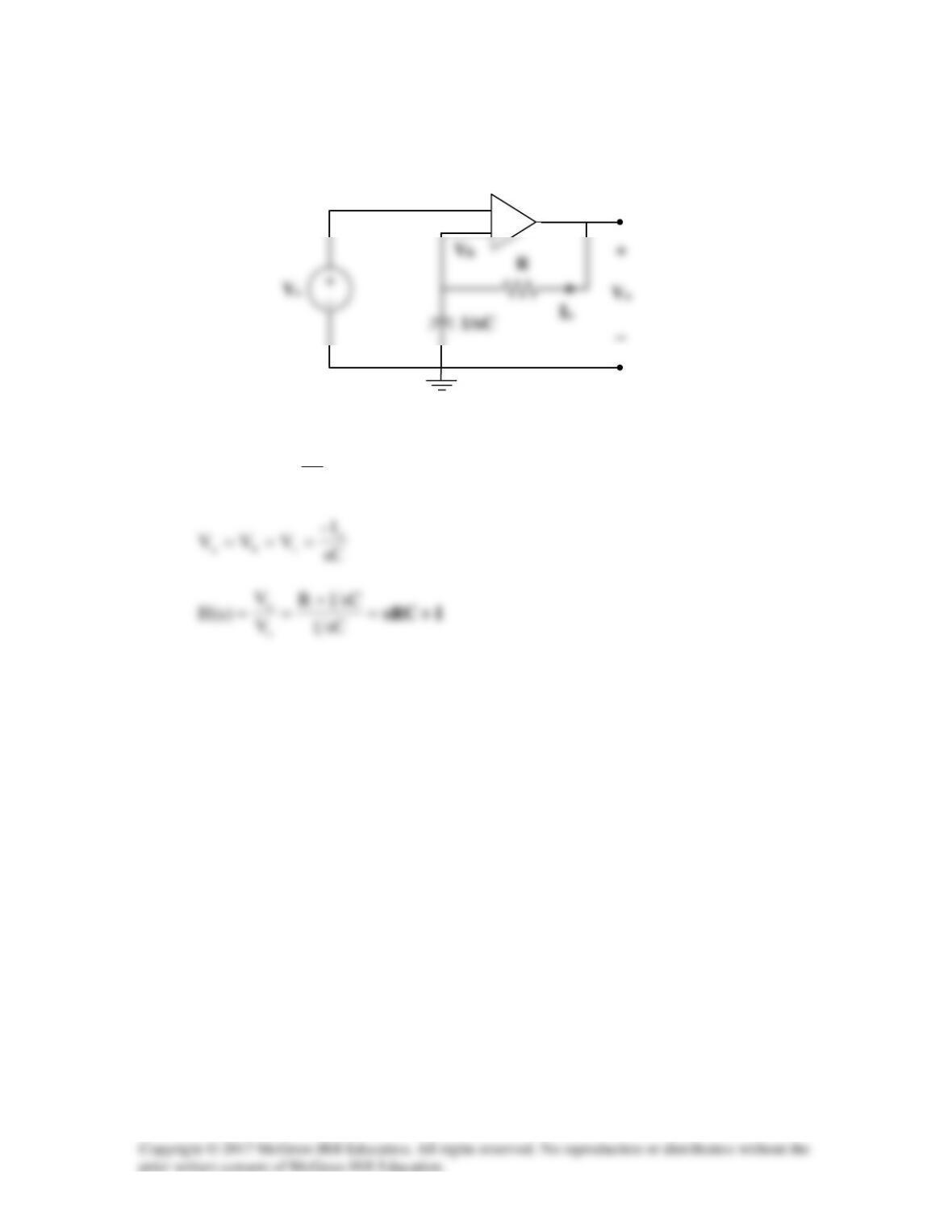
Solution 16.83
LR
R
V
o
(b)
s1)s(V)t(u)t(v ss =→=
Solution 16.84
Solution
Consider the circuit as shown below.
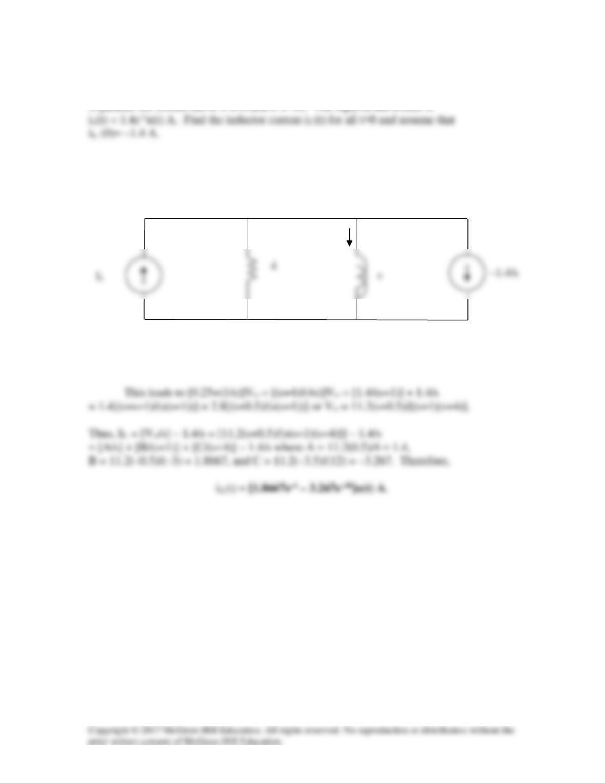
We start by writing the nodal equation, –Is + [(Vo–0)/4] + [(Vo–0)/s] – [1.4/s] = 0. We
also note that IL = [(Vo)/s] – 1.4/s and Is = 1.4/(s+1).
I
2
V
o
Solution 16.85
A circuit has a transfer function
Solution
3( 4)
( 1)( 2) 1 2 ( 2)
s AB C
Hs
+
= =++
where A = 9 and C = –6. So all we
Solution 16.86
First select the inductor current iL and the capacitor voltage vC to be the state variables.
Applying KVL we get:
1Ω
1H
i(t)
Solution 16.87
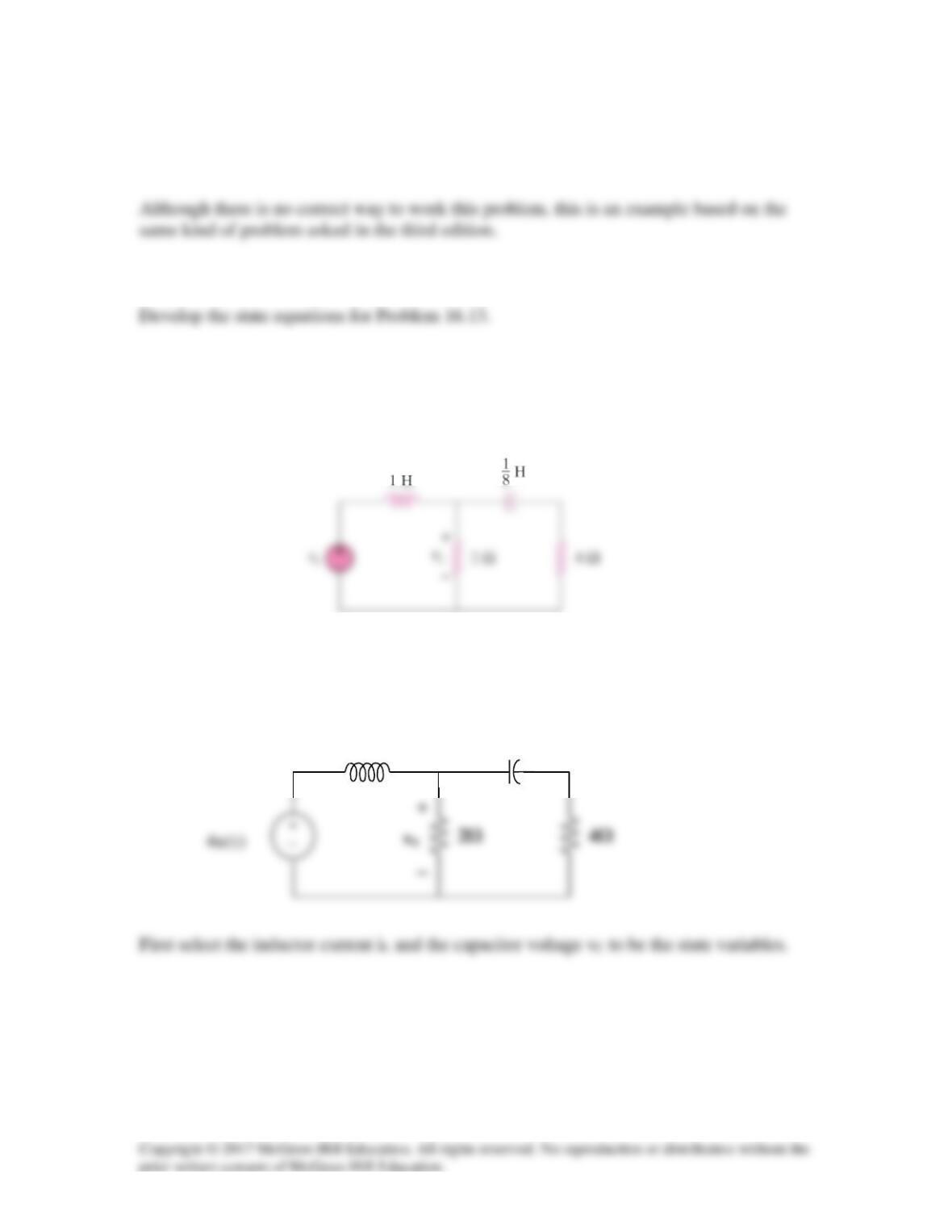
Develop the state equations for the problem you designed in Prob. 16.13.
Problem
Problem 16.13
Find vx in the circuit shown in Fig. 16.36 given vs = 4u(t) V.
Figure 16.36
Solution
1H
1/8 F
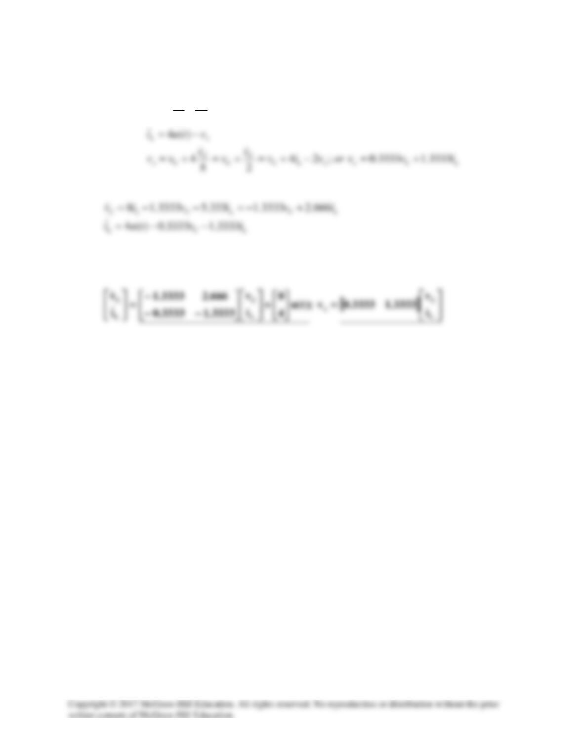
Applying KCL we get:
xLC
Cx
L
vivor
vv
i
48;0
82
−==++−
Now we can write the state equations.
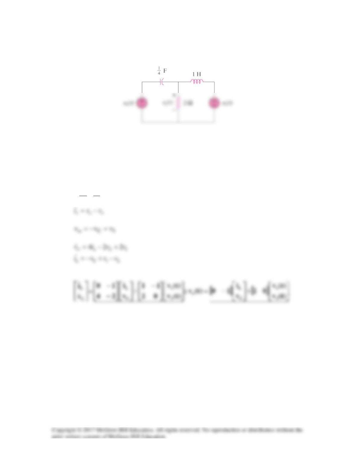
Solution 16.88
First select the inductor current iL (current flowing left to right) and the capacitor
voltage vC (voltage positive on the left and negative on the right) to be the state variables.
Applying KCL we get:
240
24
vivori
vv
oLCL
oC
+==++−