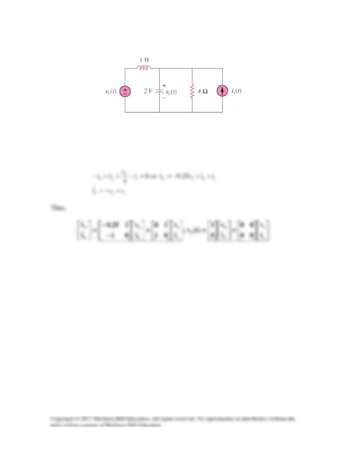
Solution 16.89
First select the inductor current iL (left to right) and the capacitor voltage vC to be the
state variables.
Letting vo = vC and applying KCL we get:
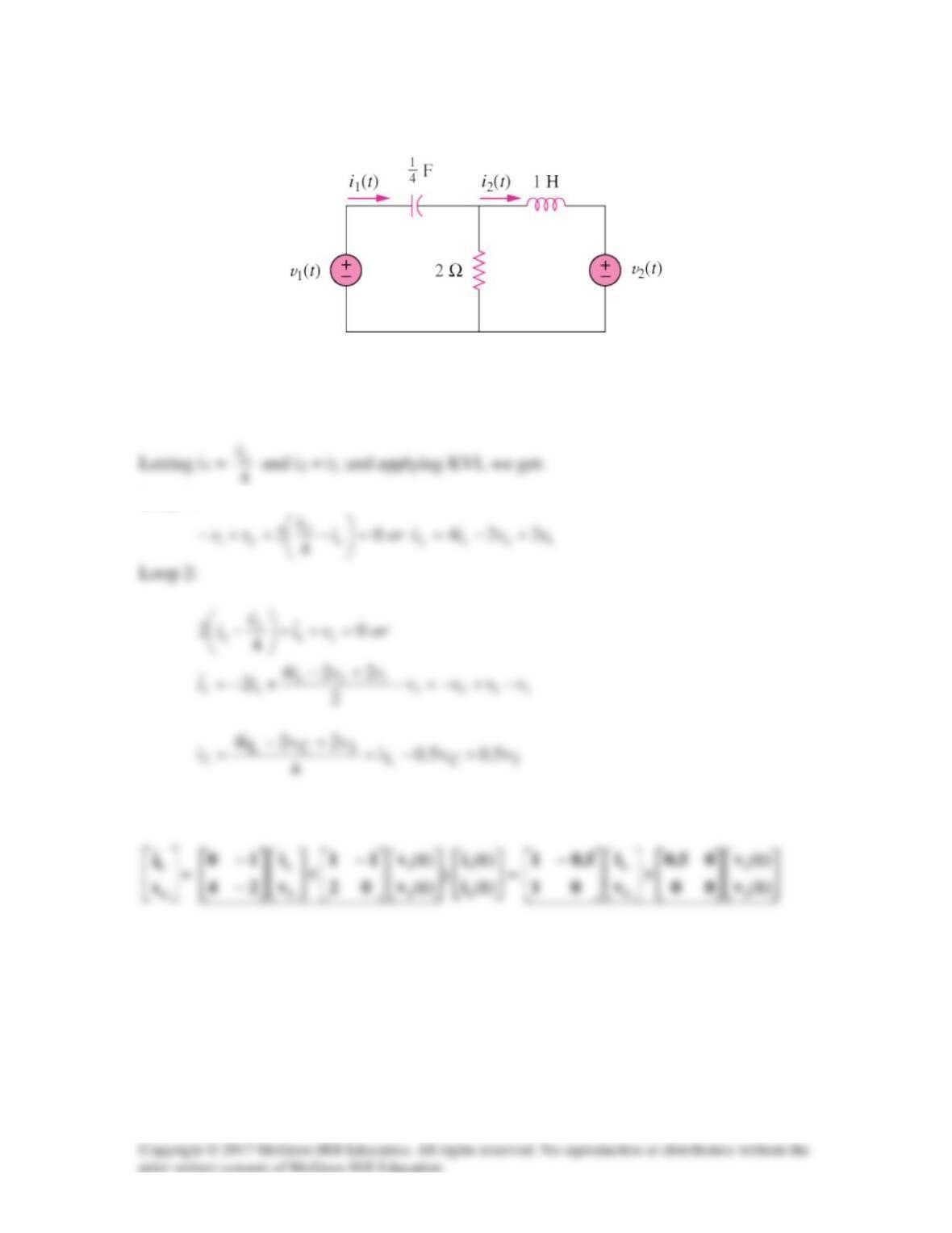
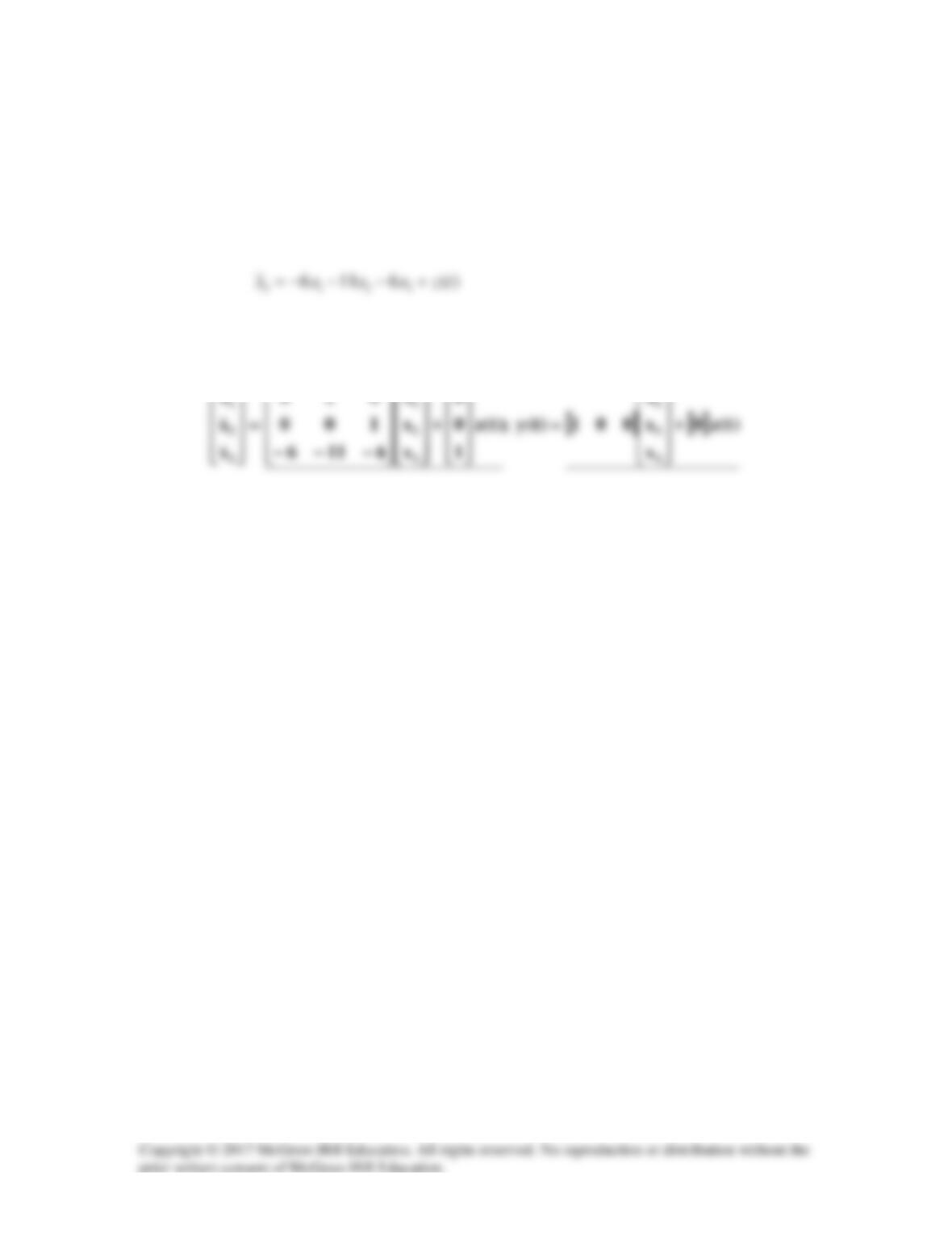
Solution 16.90
First select the inductor current iL (left to right) and the capacitor voltage vC (+ on the
left) to be the state variables.
Loop 1:
Solution 16.91
This gives our state equations.
Solution 16.92
This now leads to our state equations,
Solution 16.93
Let x1 = y(t), x2 =
., 231 xxandx =
Thus,
We can now write our state equations.
Solution 16.94
We transform the state equations into the s-domain and solve using Laplace transforms.
Assume the initial conditions are zero.
=−
s
1
B)s(X)AsI(
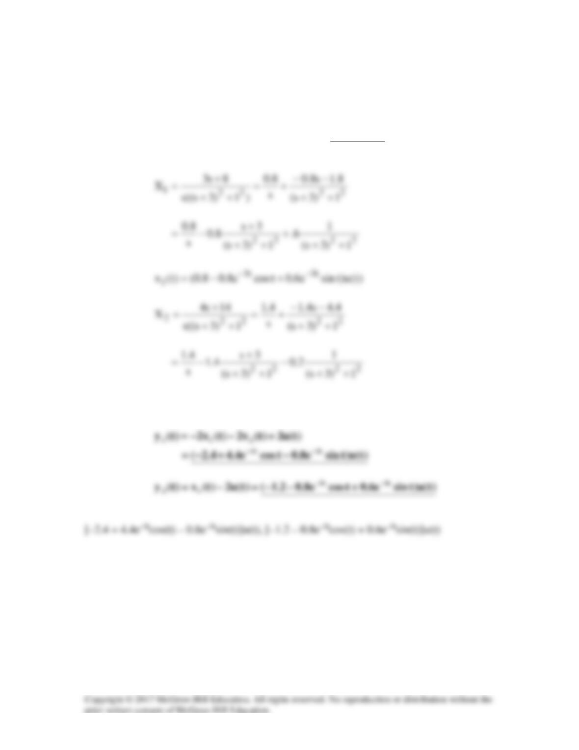
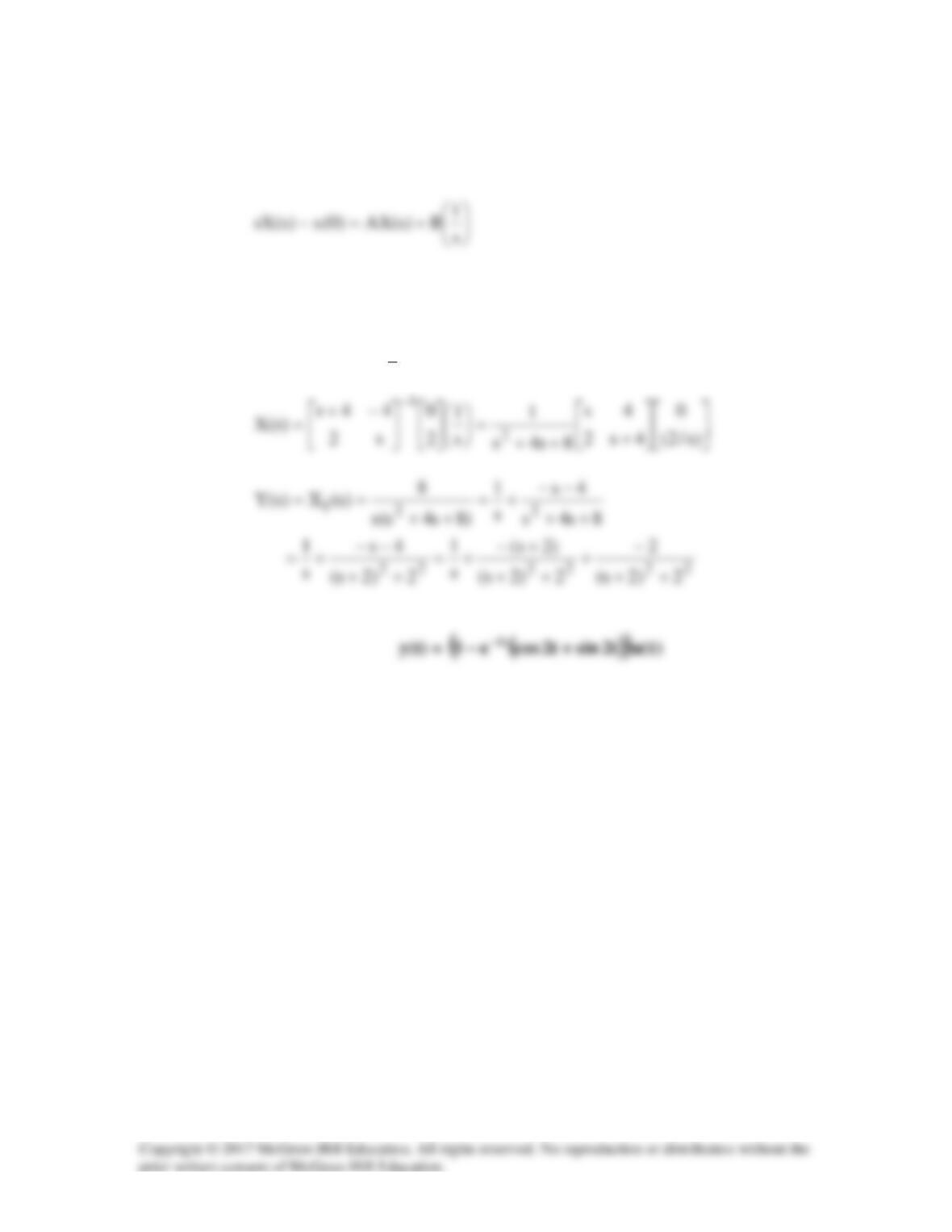
Solution 16.95
Assume that the initial conditions are zero. Using Laplace transforms we get,
+
−+
++
=
+−
+
=
−
s/4
s/3
2s2
14s
10s6s
1
s/2
s/1
04
11
4s2
12s
)s(X
2
1
)t(u)tsine2.0tcose4.14.1()t(x
t3t3
2−−
−−=
Solution 16.96
If
o
V
is the voltage across R, applying KCL at the non-reference node gives
o
o
o
o
s
V
sL
1
sC
R
1
sL
V
VsC
R
V
I
++=++=
Solution 16.97
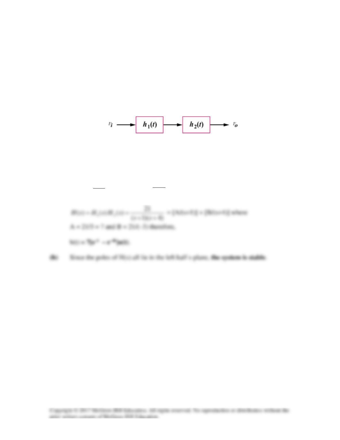
A system is formed by cascading two systems as shown in Fig. 16.106. Given that the
impulse responses of the systems are,
h1(t) = 21e–t u(t), h2(t) = e-4t u(t)
(a) Obtain the impulse response of the overall system.
(b) Check if the overall system is stable.
Figure 16.106
For Prob. 16.97.
Solution
(a)
1
21
)(
1
+
=s
sH
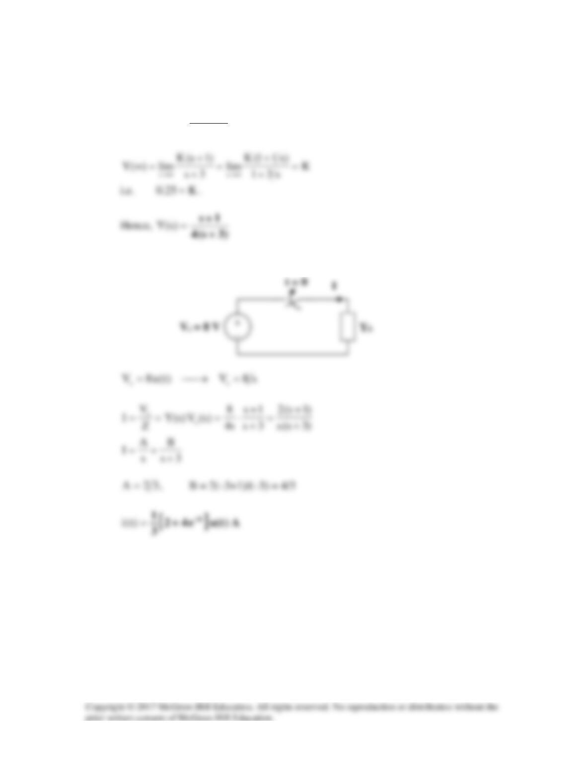
,
4s
1
)s(H2+
=
Solution 16.98
Let
1o
V
be the voltage at the output of the first op amp.
Solution 16.99
LCs1
sL
sC
1
sL
sC
1
sL
sC
1
||sL 2
+
=
+
⋅
=
Comparing this with the given transfer function,
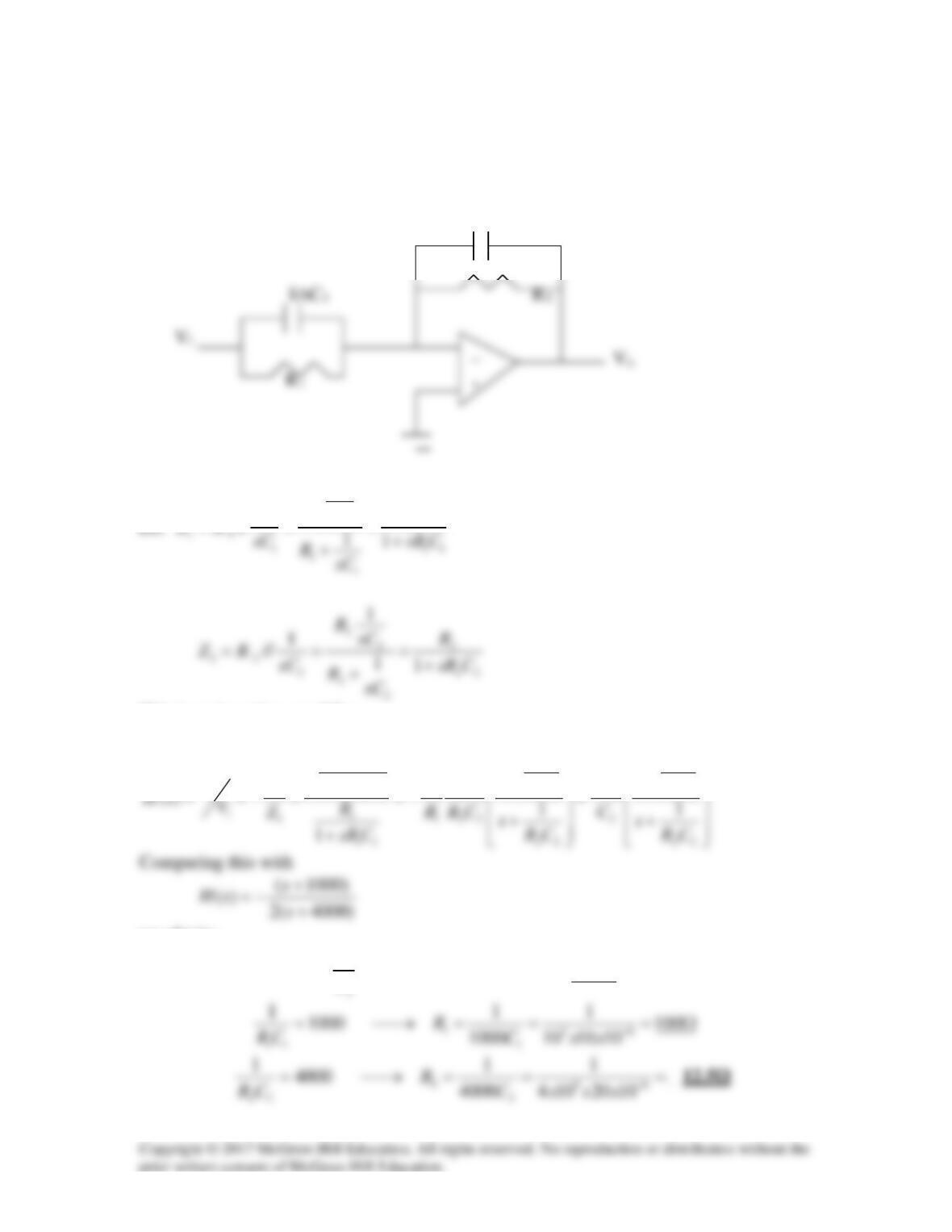
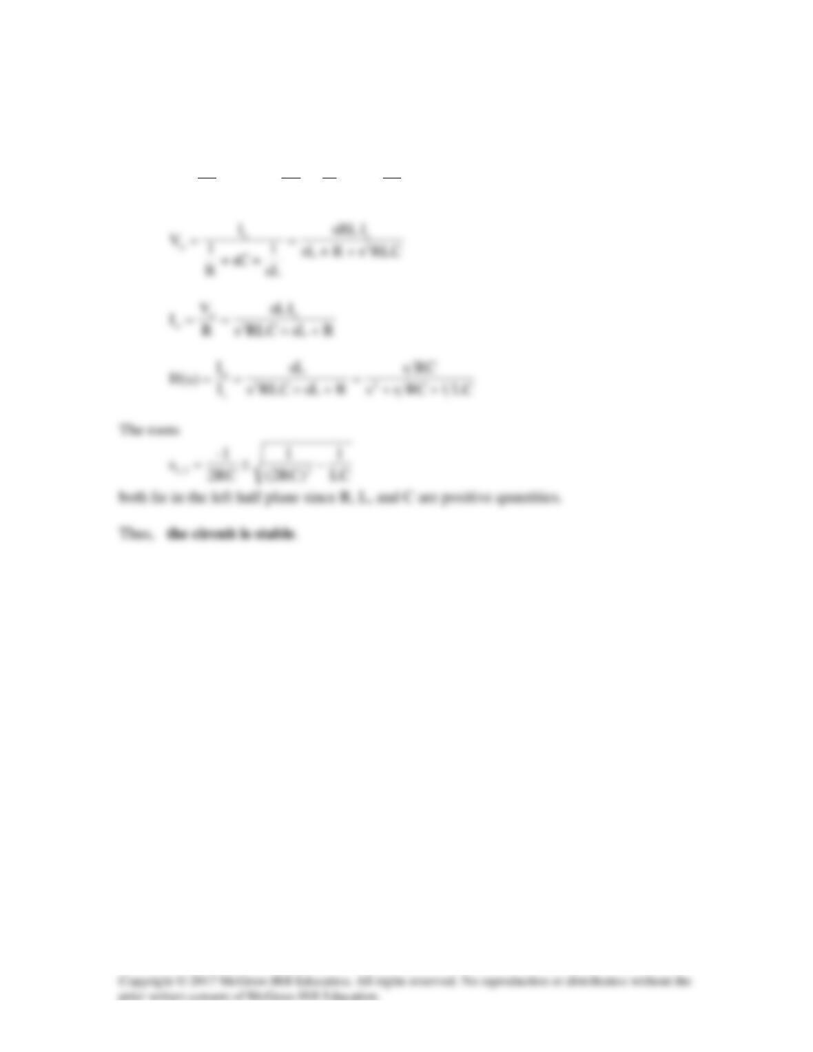
Solution 16.100
The circuit is transformed in the s-domain as shown below.
1/sC2
1
1
1
1
1
RR
sC
This is an inverting amplifier.
2
2 2 11 1
2 2 11 11
11
1
o
Rss
Z R RC C
sRC RC RC
V
− ++
−
+
we obtain:
1
21
1/ 2 2 20
CCC F
C
µ
= → = =
Solution 16.101
We apply KCL at the noninverting terminal at the op amp.
)YY)(V0(Y)0V( 21o3s −−=−
Comparing this with the given transfer function,
Solution 16.102
Consider the circuit shown below. We notice that
o3 VV =
and
o32 VVV ==
.
At node 2,
3o2o1 Y)0V(Y)VV( −=−
Substituting (2) into (1),
)YY(VV)YYY(
YY
YV
32
+−++⋅
+
=
1
Y
and
2
Y
must be resistive, while
3
Y
and
4
Y
must be capacitive.
Y4
2121
o
CCRR
1
V
Choose
Ω= k1R1
, then
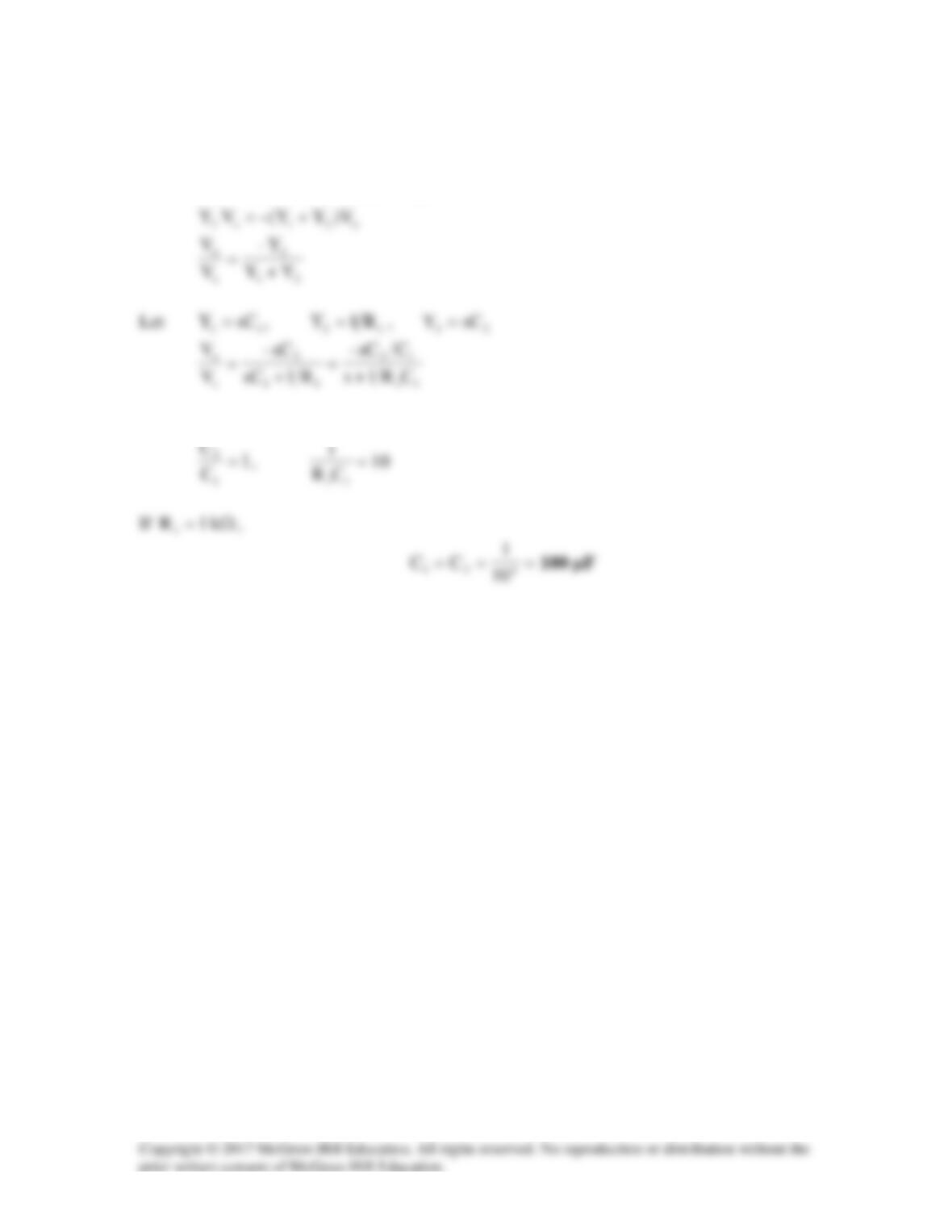
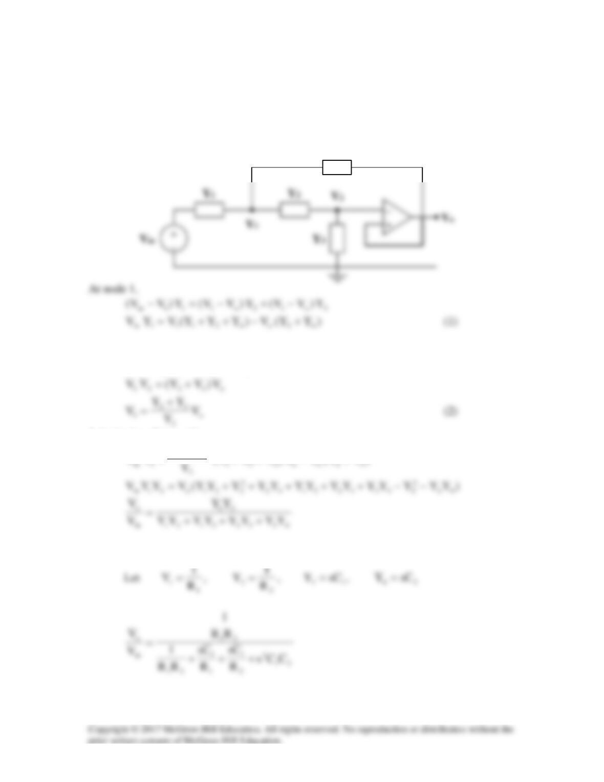
Solution 16.103
Using the result of Practice Problem 16.14,
YY–
V
21
o
When
11
sCY=
,
F5.0C
1
µ=
Therefore,
Solution 16.104
(a) Let
3s
)1s(K
)s(Y +
+
=
(b) Consider the circuit shown below.
Solution 16.105
The gyrator is equivalent to two cascaded inverting amplifiers. Let
1
V
be the voltage at
the output of the first op amp.
ii1 -VV
R
R–
V==