Solution 10.32
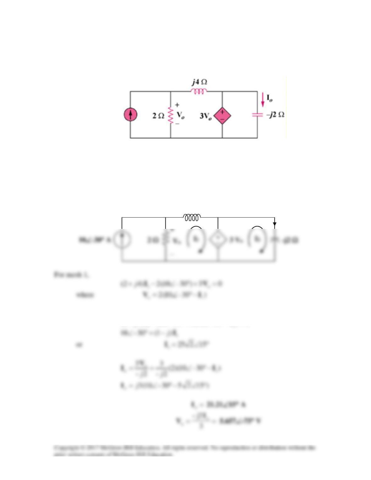
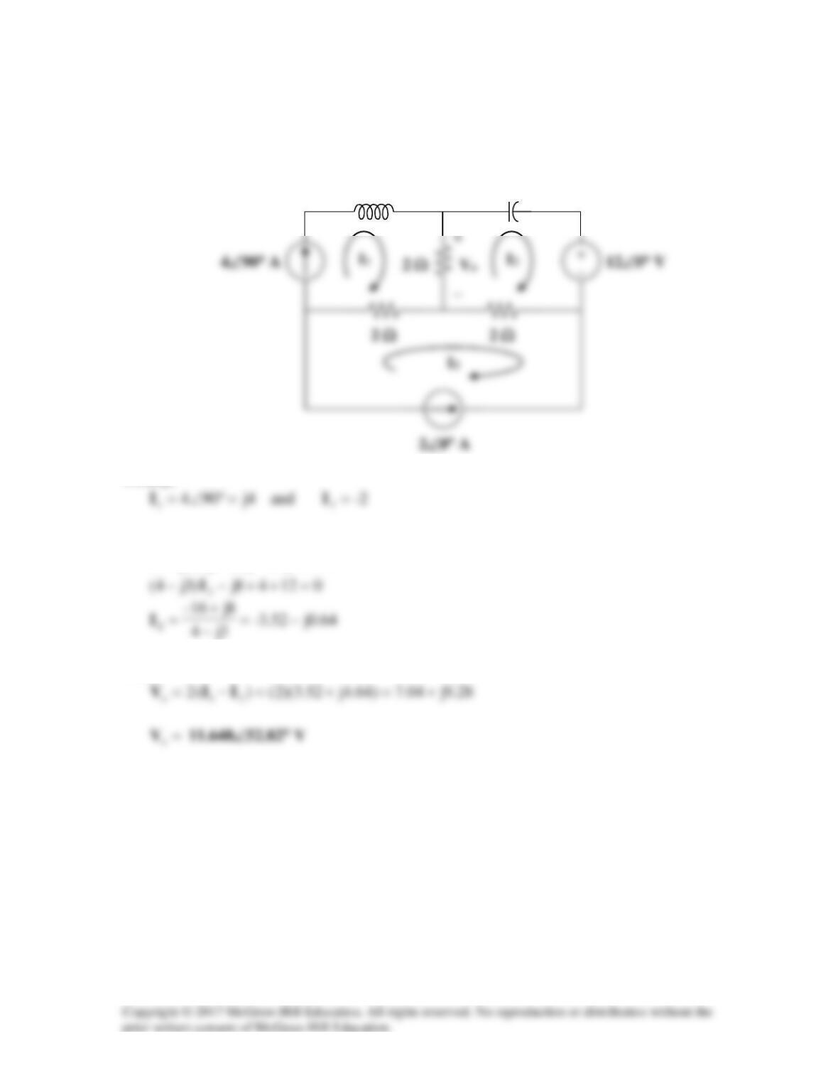
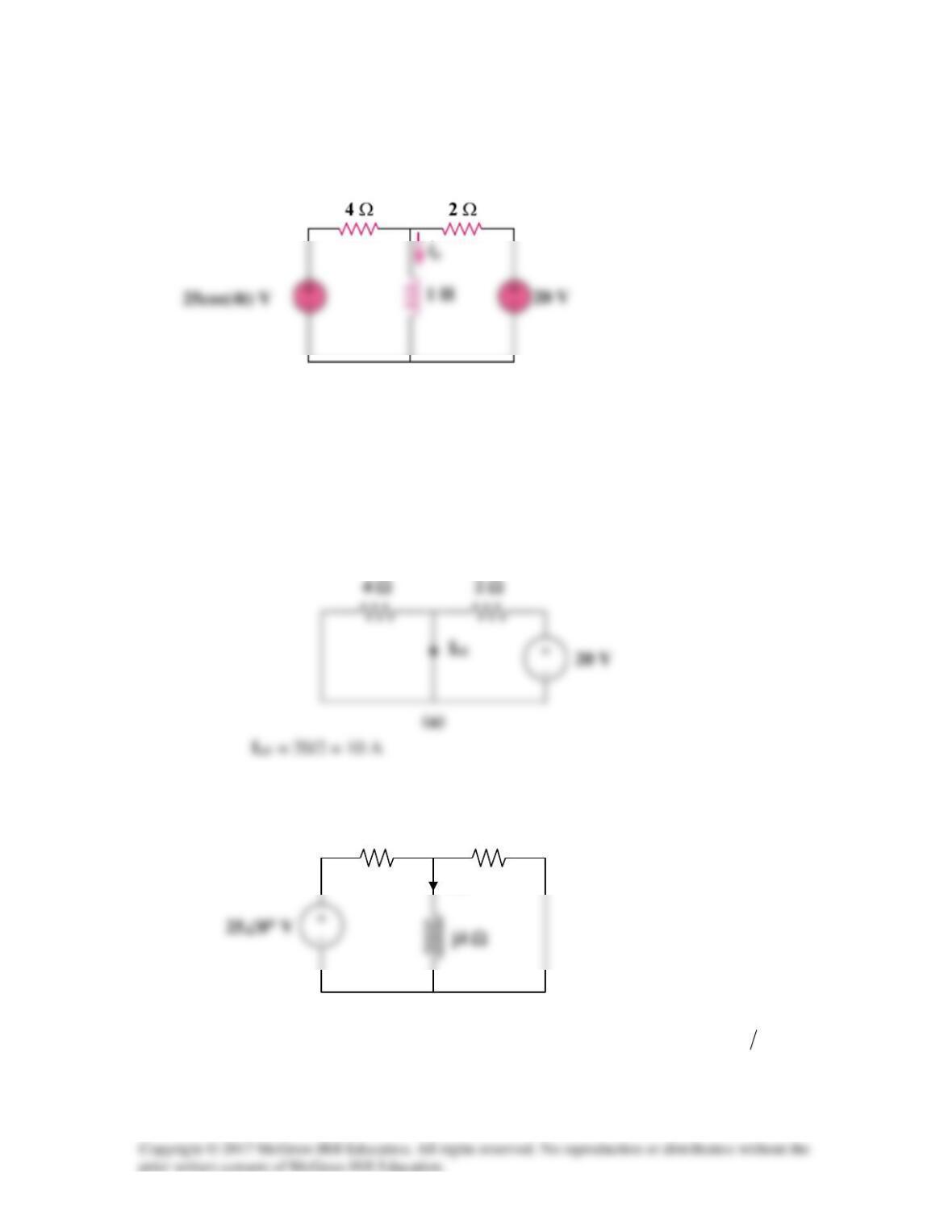
Determine Vo and Io in the circuit of Fig. 10.80 using mesh analysis.
Figure 10.80
For Prob. 10.32.
Solution
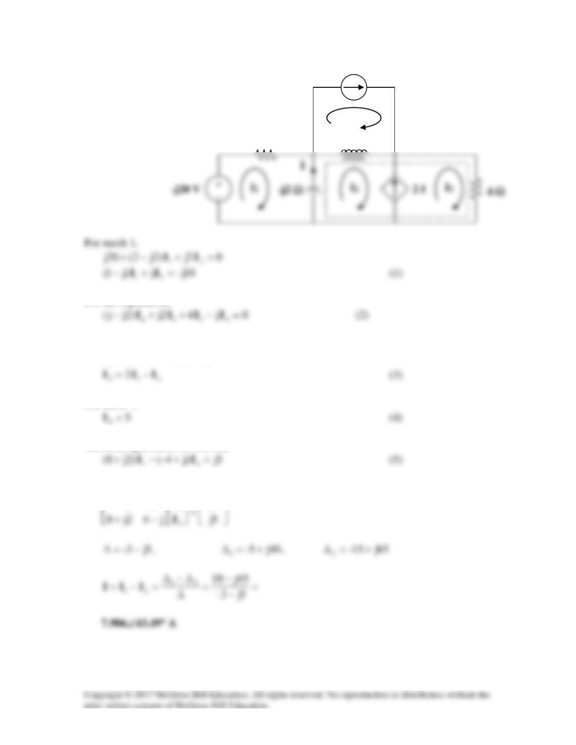
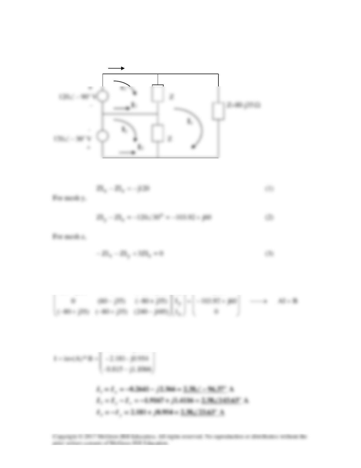
Consider the circuit below.
I2
I1
Hence,
0)30–10(630–20)42( 11 =−°∠+°∠−+ IIj
j4 Ω
Io
10∠–30° A
5 A
I2
I1
I3
2 Ω
I4
j Ω
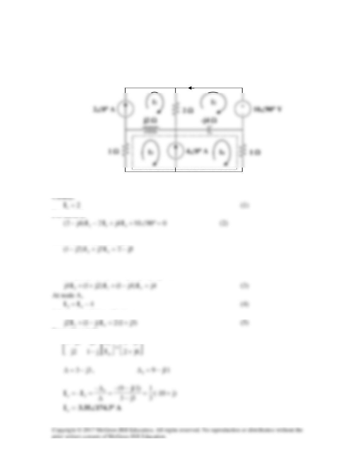
Solution 10.33
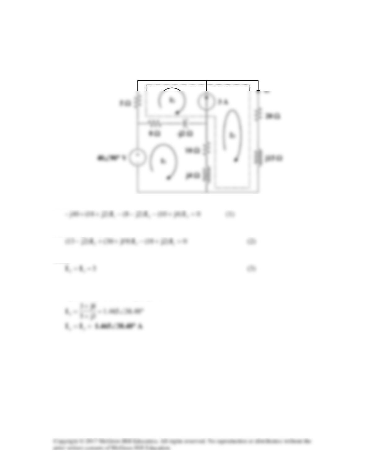
Consider the circuit shown below.
For the supermesh,
Also,
)(22
2123
IIIII −==−
For mesh 4,
Substituting (3) and (4) into (2),
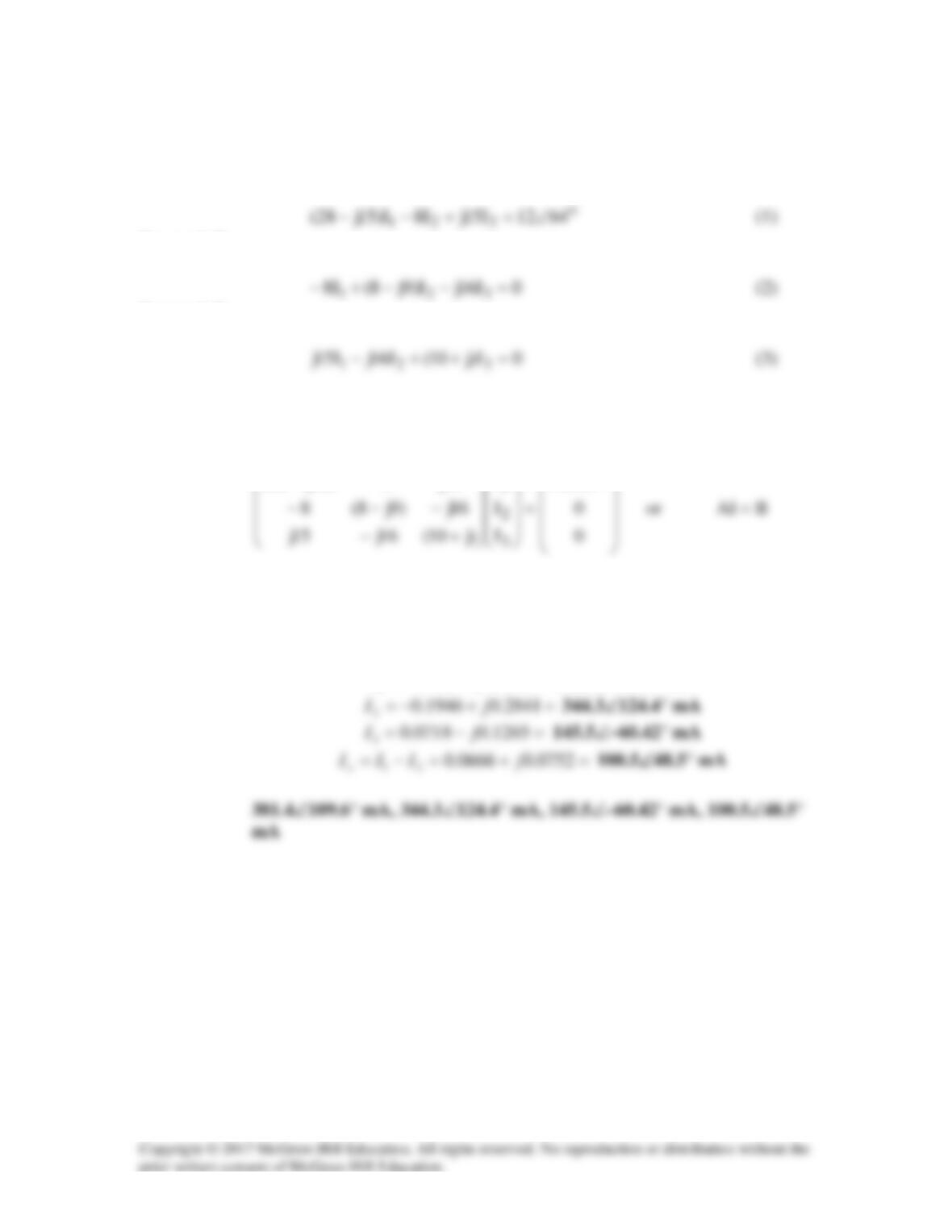
Putting (1) and (5) in matrix form,
−
10j–
jj1
1
I
Solution 10.34
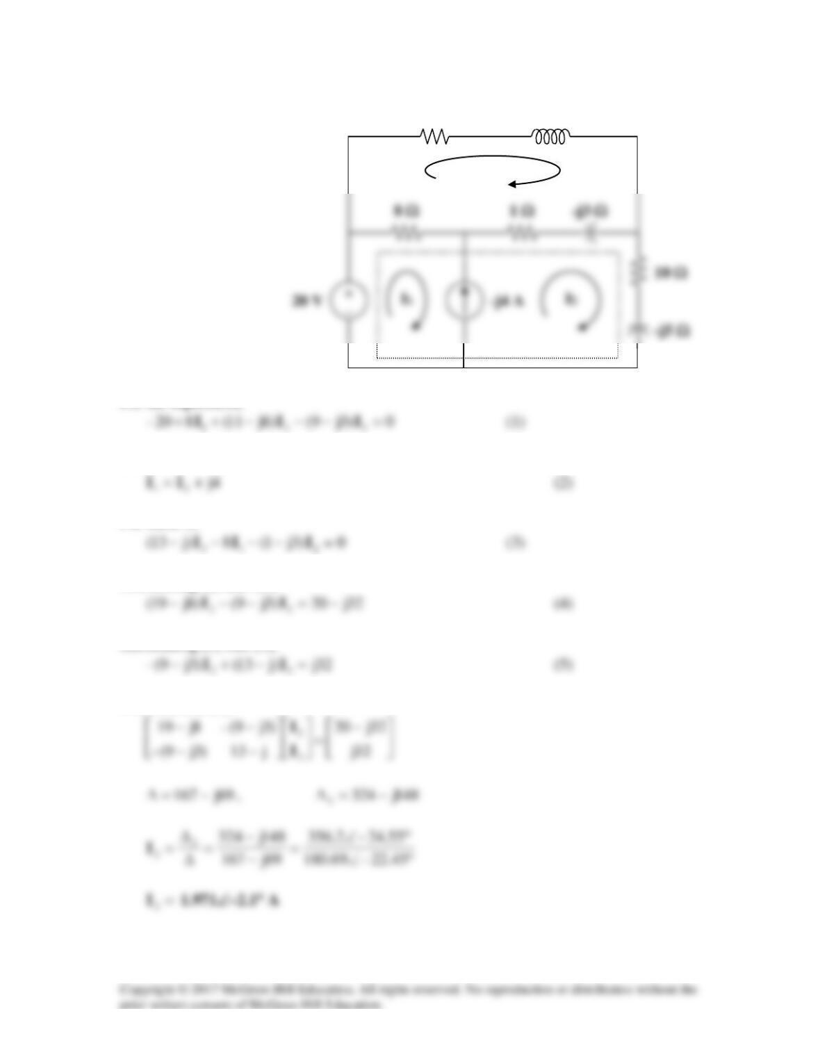
The circuit is shown below.
For mesh 1,
For the supermesh,
Also,
Adding (1) and (2) and incorporating (3),
0)15j20()3(540j– 33 =++−+ II
j2 Ω
8 Ω
4 Ω
I
3
Solution 10.35
Consider the circuit shown below.
For the supermesh,
Also,
For mesh 3,
Substituting (2) into (1),
Substituting (2) into (3),
From (4) and (5),
Solution 10.36
Consider the circuit below.
Clearly,
For mesh 2,
01222)3j4( 312 =+−−− III
Thus,
j4 Ω
–j3 Ω
Solution 10.37
I1
For mesh x,
Putting (1) to (3) together leads to the following matrix equation:
120j
I
)35j80(0)35j80(
x
−
+−−
Using MATLAB, we obtain
−
j2.366 0.2641–
Solution 10.38
Consider the circuit below.
For mesh 2,
Substitute (1) into (2) to get
For the supermesh,
04j)4j1(2j)2j1( 2413 =+−+−+ IIII
Substituting (4) into (3) gives
From (2) and (5),
−
−
5j2
2j2j1
I
Io
A
Solution 10.39
For mesh 1,
For mesh 2,
For mesh 3,
In matrix form, (1) to (3) can be cast as
6412
I
15j8)15j28( o
1
∠
−−
Using MATLAB,
I = inv(A)*B
=+−= 3593.0128.0
1
jI
381.4∠109.6° mA
Solution 10.40
Find io in the circuit shown in Fig. 10.85 using superposition.
Figure 10.85
For Prob. 10.40.
Solution
Let Io = Io1 + Io2, where Io1 is due to the dc source and Io2 is due to the ac source. For
Io1, consider the circuit in Fig. (a).
Clearly,
2 Ω
4 Ω
(a)
For Io2, consider the circuit in Fig. (b).
If we transform the voltage source, we have the circuit in Fig. (c), where
Ω= 342||4
.
2 Ω
4 Ω
Io2
(b)
By the current division principle,
)025.6(
34
=
I
Io2
(c)
Solution 10.41
Find vo for the circuit in Fig. 10.86 assuming that is(t) = 2sin(2t) + 3cos(4t) A.
Figure 10.86
For Prob. 10.41.
Solution
This problem is easily solved using superposition. Vo = Is[10(j5ω)]/(10+j5ω).
Solution 10.42
Using Fig. 10.87, design a problem to help other students to better understand the
Problem
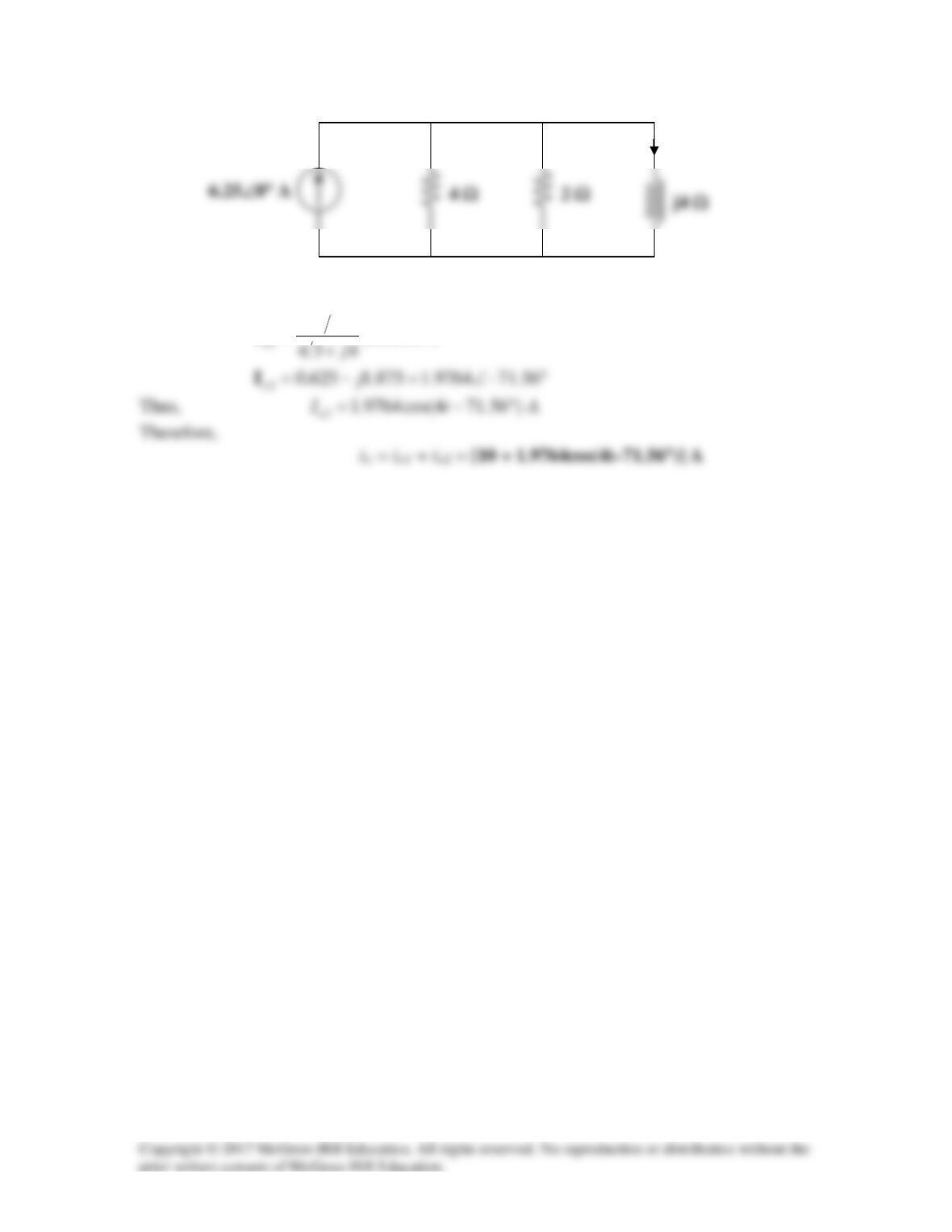
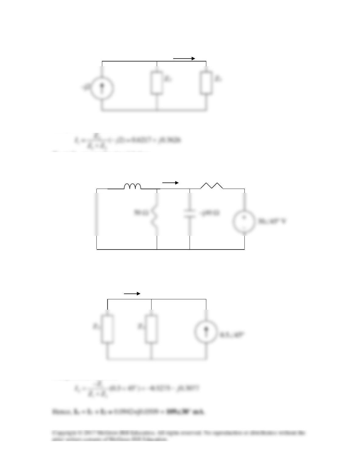
Solve for Io in the circuit of Fig. 10.87.
Io
j10 Ω 60 Ω
Figure 10.87 For Prob. 10.42.
Solution
Let
12o
I II= +
where I1 and I2 are due to 20<0o and 30<45o sources respectively. To get I1, we use the
circuit below.
I1
j10 Ω 60 Ω
I1
Using current division,
To get I2, we use the circuit below.
I2
j10 Ω 60 Ω
After transforming the voltage source, we obtain the circuit below.
I2
Using current division,
Solution 10.43
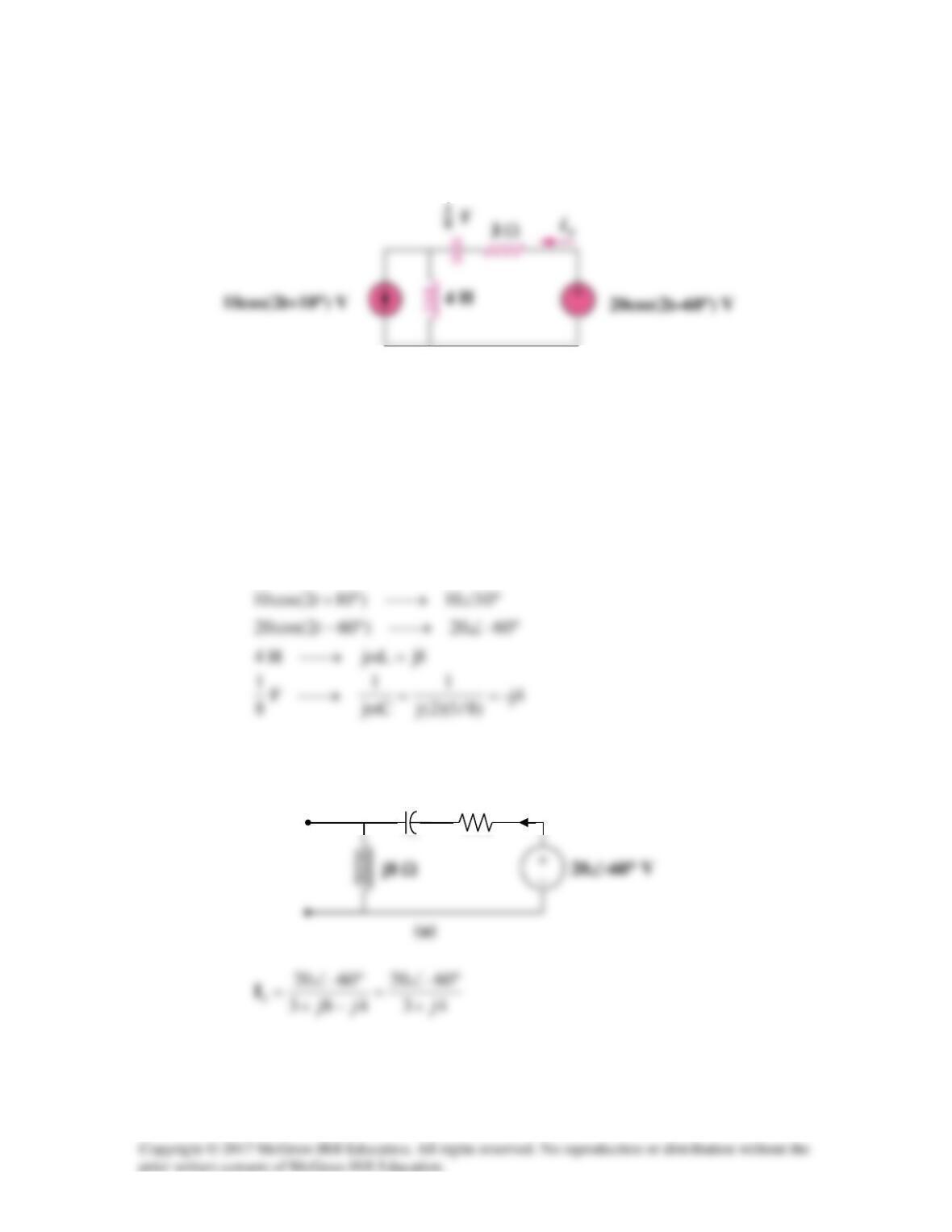
Using the superposition principle, find ix in the circuit of Fig. 10.88.
10cos(2t+10°) V
Figure 10.88
For Prob. 10.43.
Solution
Let
21x III +=
, where
1
I
is due to the voltage source and
2
I
is due to the current
source.
2=ω
For
1
I
, consider the circuit in Fig. (a).
–j4 Ω
3 Ω
I1
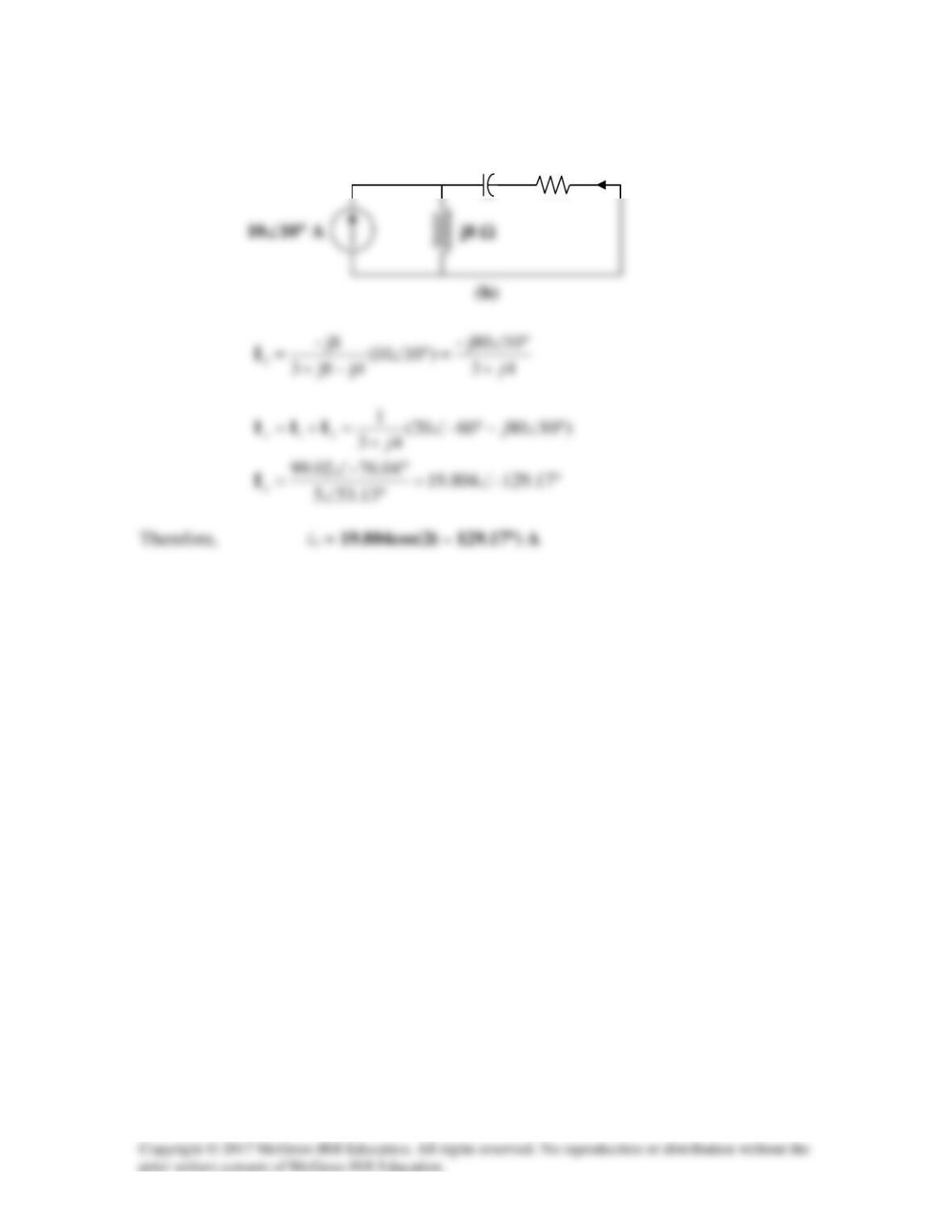
For
2
I
, consider the circuit in Fig. (b).
–j4 Ω
3 Ω
I2
Solution 10.44
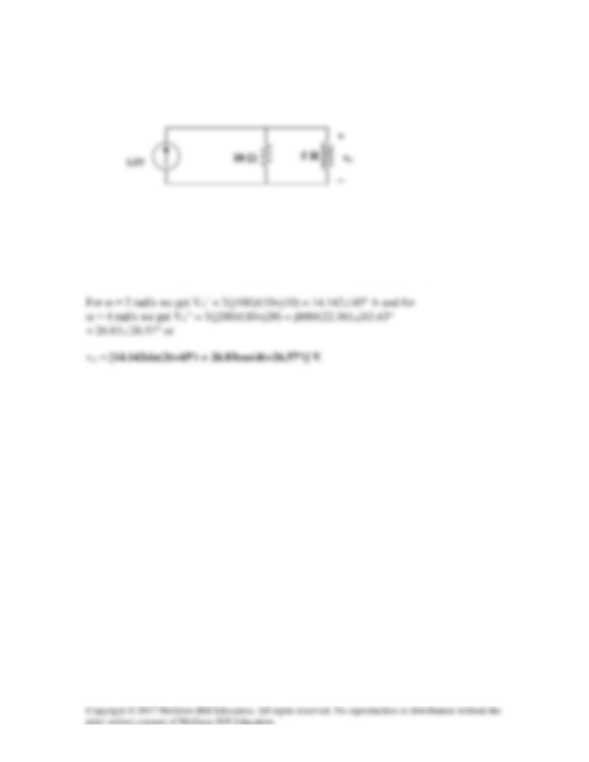
Use superposition principle to obtain vx in the circuit of Fig. 10.89. Let vs = 50 sin2t V
and is = 12 cos(6t + 10°) A.
Figure 10.89
For Prob. 10.44.
Solution
Let
21x vvv +=
, where v1 and v2 are due to the voltage source and current source
respectively.
For v2, ω = 6 rad/s and the capacitive reactance is equal to –j(10/3) Ω and Is = 12 A.
Note we will adjust the angle after we calculate the value of V2 during the conversion
Solution 10.45
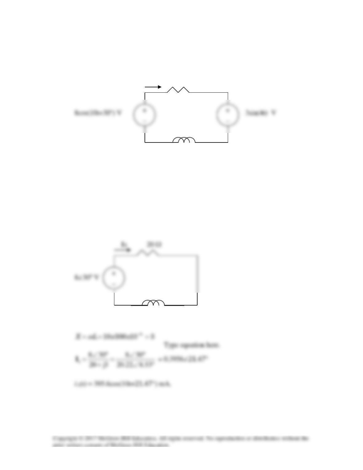
Use superposition to find i(t) in the circuit of Fig. 10.90.
i 20 Ω
300 mH
Figure 10.90
For Prob. 10.45.
Solution
Let i = i1 + i2, where i1 and i2 are due to 8cos(10t +30o) and 3sin4t sources respectively.
To find i1, consider the circuit below.
jX
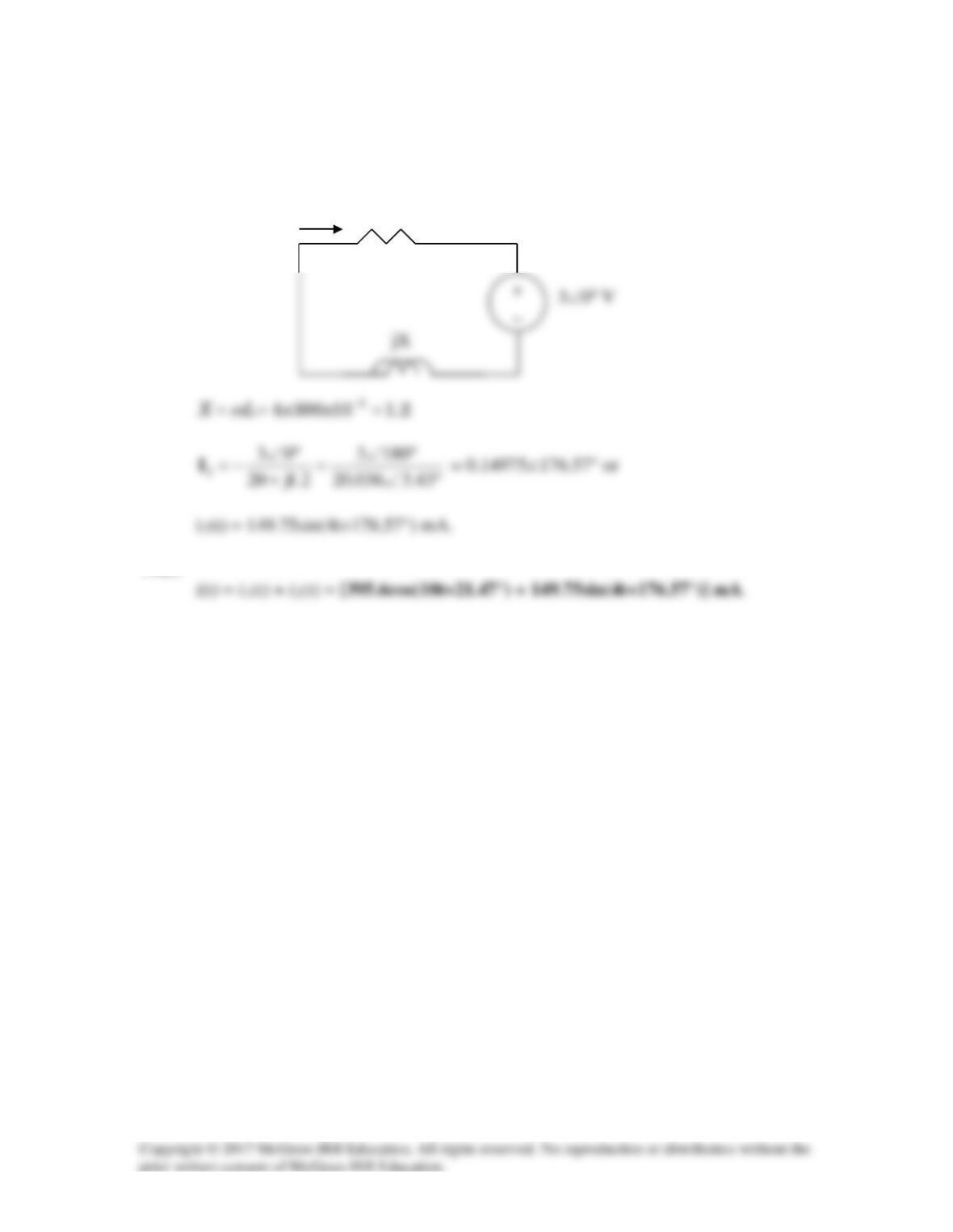
To find i2(t), consider the circuit below,
I2 20 Ω
Thus,
Solution 10.46
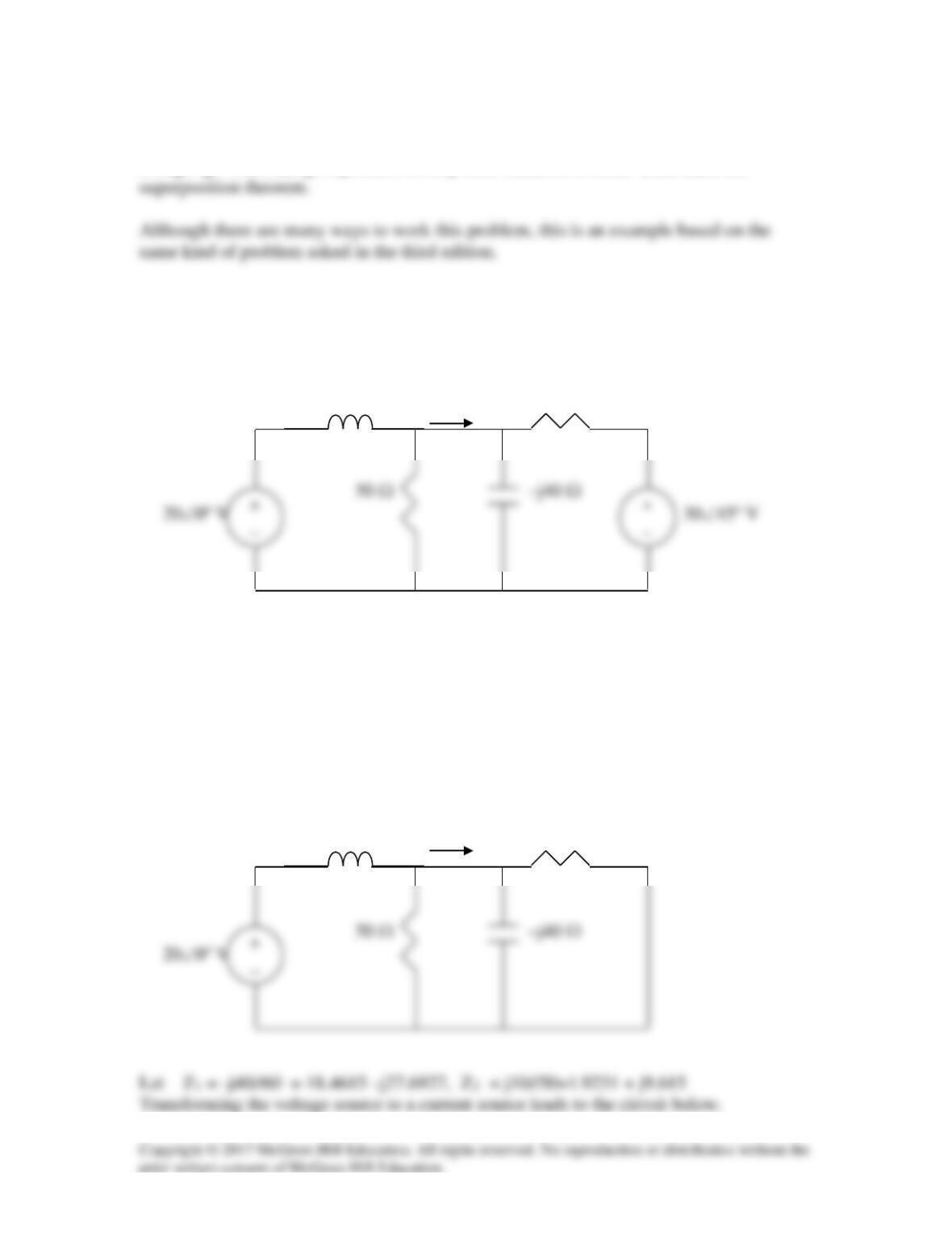
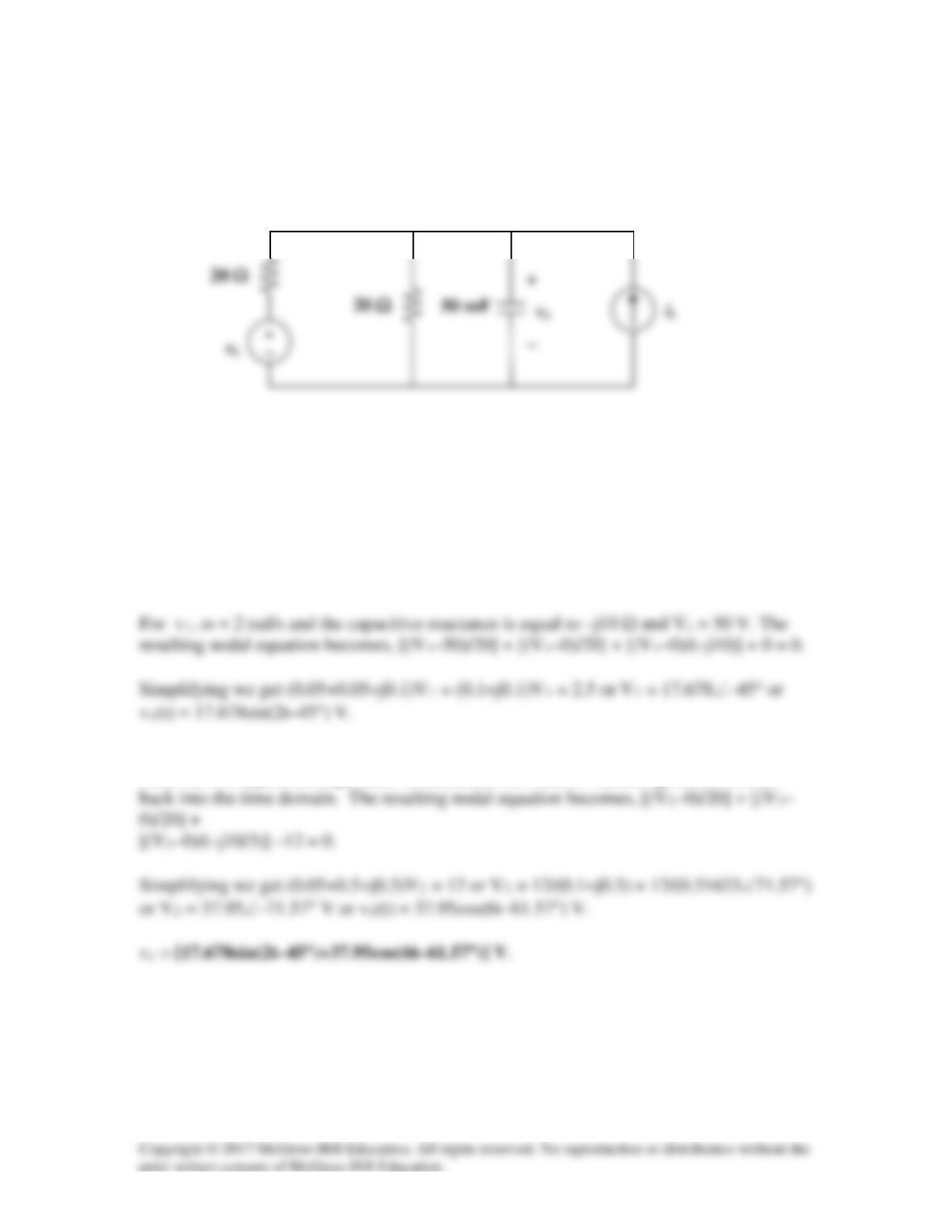
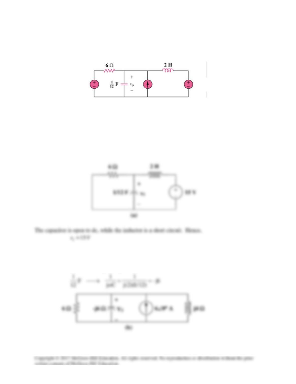
Solve for vo(t) in the circuit of Fig. 10.91 using the superposition principle.
Figure 10.91
For Prob. 10.46.
Solution
Let vo = v1 + v2 + v3, where V1, V2, and V3 are respectively due to the 15-V dc source, the ac
current source, and the ac voltage source. For
1
v
consider the circuit in Fig. (a).
For
2
v
, consider the circuit in Fig. (b).
2=ω
4jLjH2 =ω→
6sin(2t) A
15 V
18cos(3t) V
Applying nodal analysis,
2
222
466
1
46–6
6V
VVV
−+=++= jj
jj
For
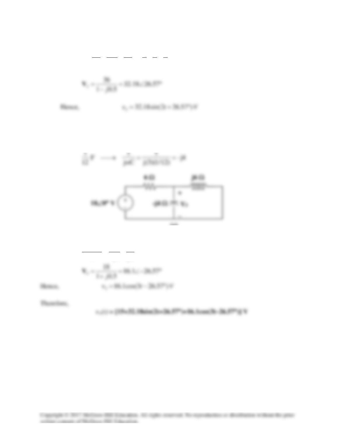
3
v
, consider the circuit in Fig. (c).
3=ω
6jLjH2 =ω→
At the non-reference node,
64–6
18 333
jj
VVV +=
−
(c)