Solution 7.19
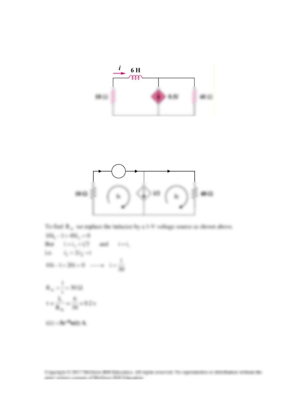
In the circuit of Fig. 7.99, find i(t) for t > 0 if i(0) = 5 A.
Figure 7.99
For Prob. 7.19.
Solution
− +
i
i1
i2
1 V
Solution 7.20
(a)
L50R
50
1
R
L=→==τ
(c)
=== 22 )30)(06.0(
2
1
)0(
2
1iLw
27 J
The value of the energy remaining at 10 ms is given by:
Solution 7.21
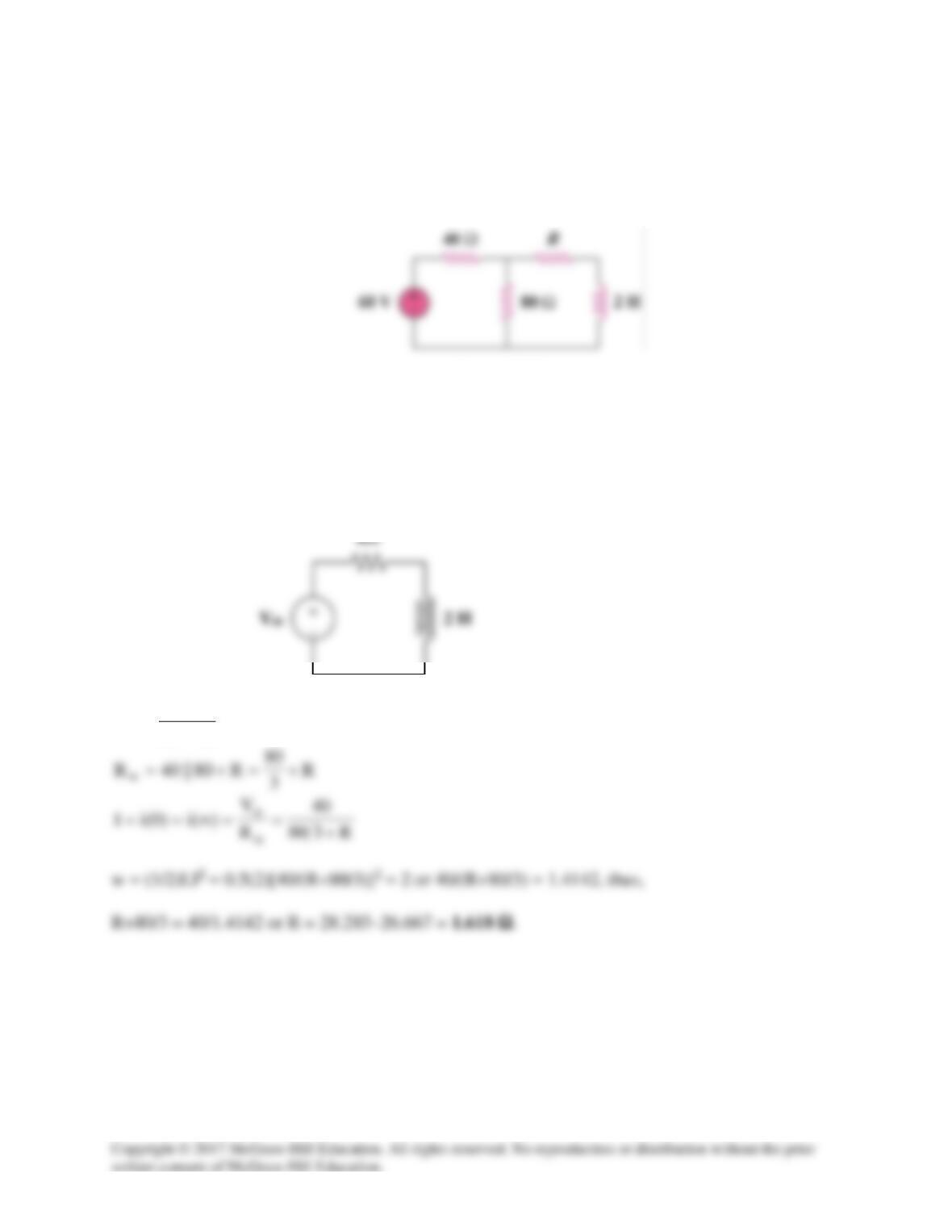
In the circuit in Fig. 7.101, find the value of R for which the steady–state energy stored in the
inductor will be 2 J.
Figure 7.101
For Prob. 7.21.
Solution
The circuit can be replaced by its Thevenin equivalent shown below.
V40)60(
4080
80
V
th
=
+
=
Solution 7.23
Since the 2 Ω resistor, 1/3 H inductor, and the (3+1) Ω resistor are in parallel, they
always have the same voltage.
The Thevenin resistance
th
R
at the inductor’s terminals is
Solution 7.24
(c)
[ ] [ ]
)3t(u)2t(u)2t(u)1t(u)1t()t(x −−−+−−−−=
Solution 7.25
Design a problem to help other students to better understand singularity functions.
Problem
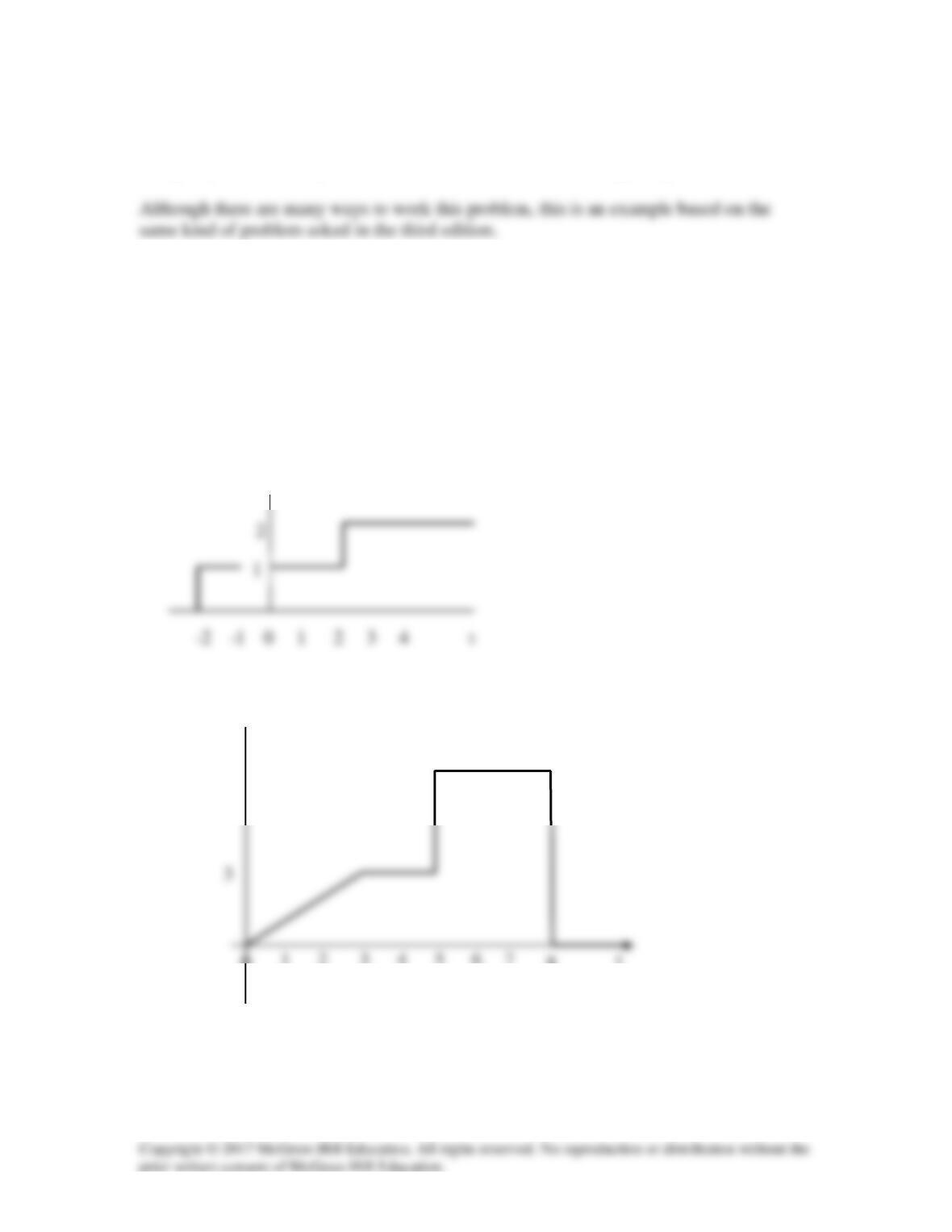
Sketch each of the following waveforms.
(a) i(t) = [u(t–2)+u(t+2)] A
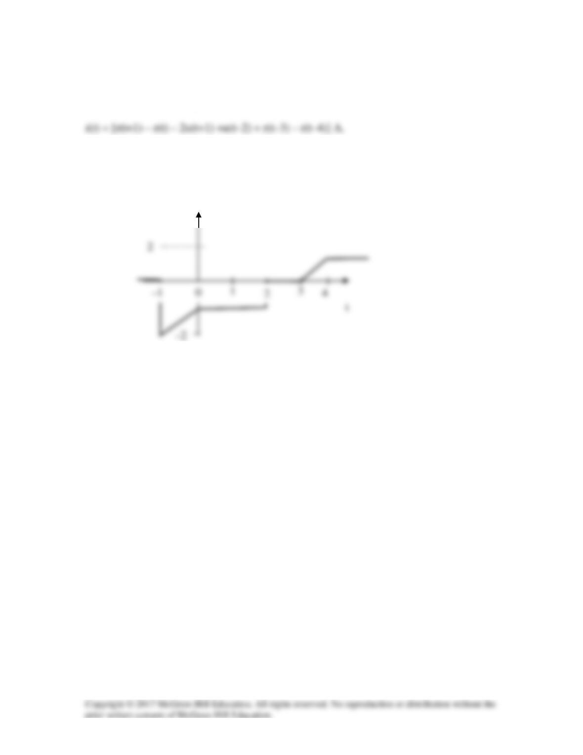
(b) v(t) = [r(t) – r(t–3) + 4u(t–5) – 8u(t–8)] V
Solution
The waveforms are sketched below.
(a) i(t) (A)
(b)
v(t) (V)
7
0 1 2 3 4 5 6 7 8 t
–1
0
8
Solution 7.26
(b)
[ ]
)4t(u)2t(u)t4()t(v2−−−−=
Solution 7.27
Solution 7.28
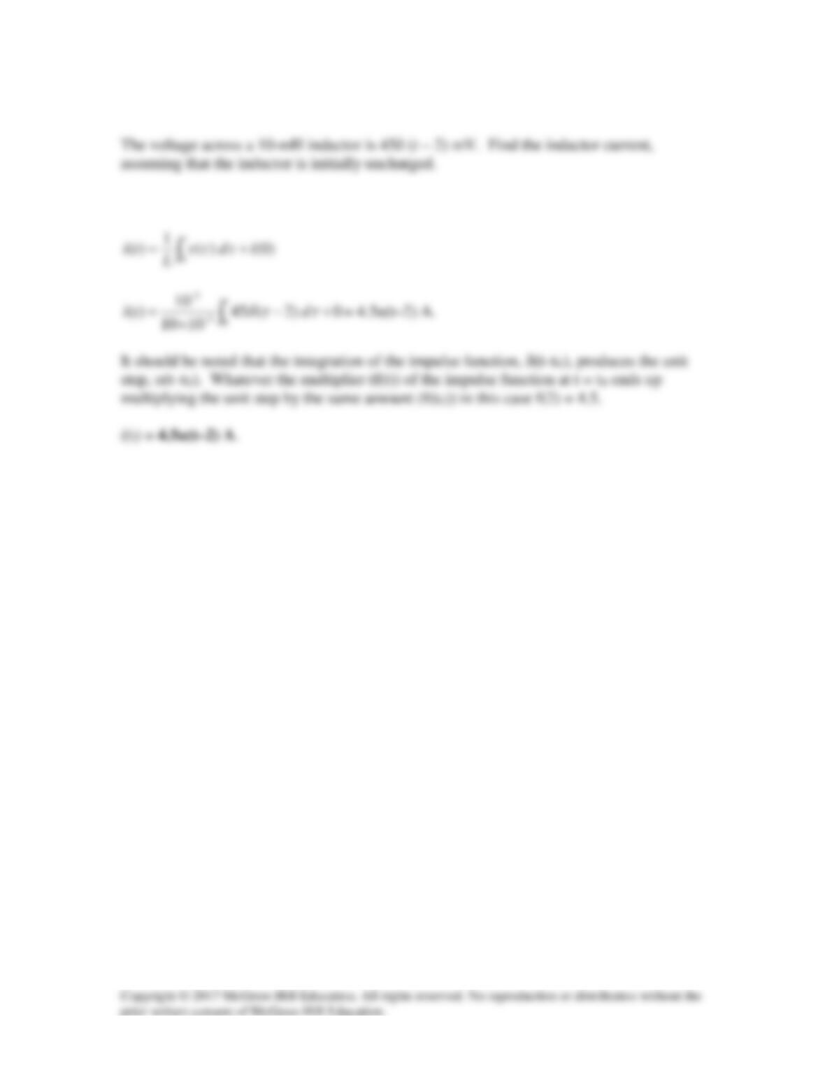
Sketch the waveform represented by
Solution
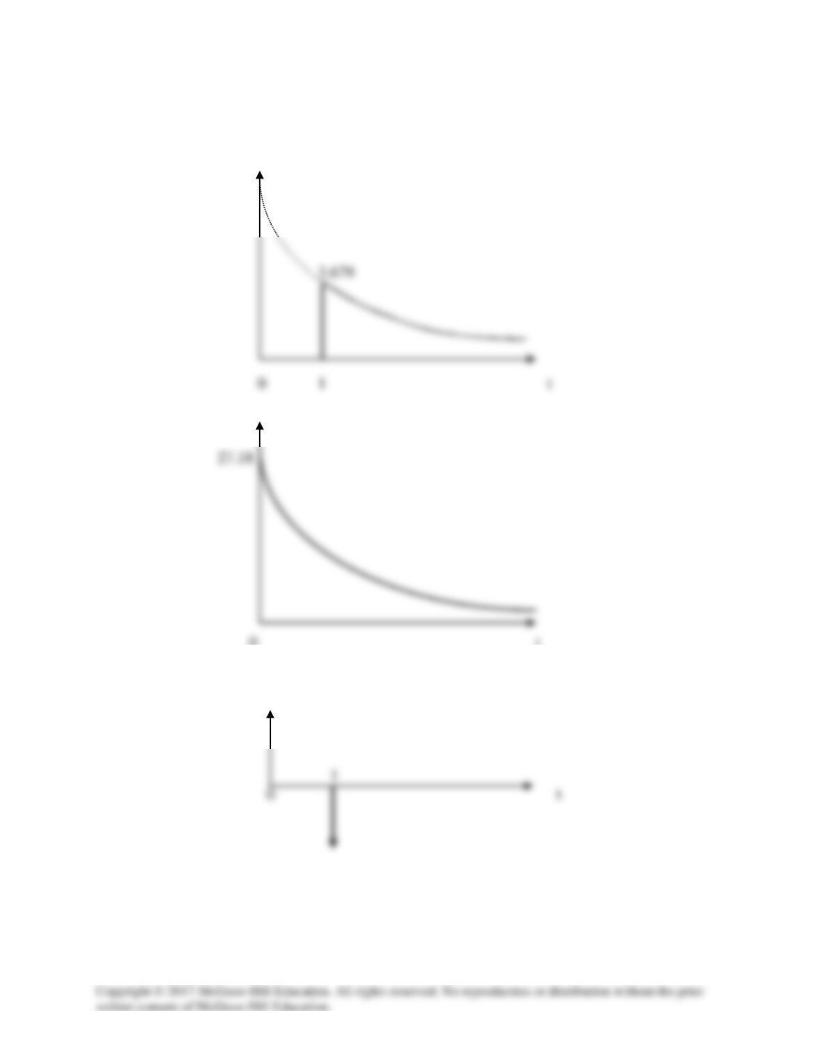
i(t) is sketched below.
i(t)
Solution 7.29
x(t)
(a)
(b) y(t)
0 t
(c)
)1(6536.0)1(4cos)1(4cos)( −−=−=−= tttttz
δδδ
, which is sketched below.
z(t)
–0.653δ(t–1)
Solution 7.30
∞
∫cos)t2cos(t4dt)5.0t(
5.0t
–
Solution 7.31
Solution 7.32
Solution 7.33
Solution
Solution 7.34
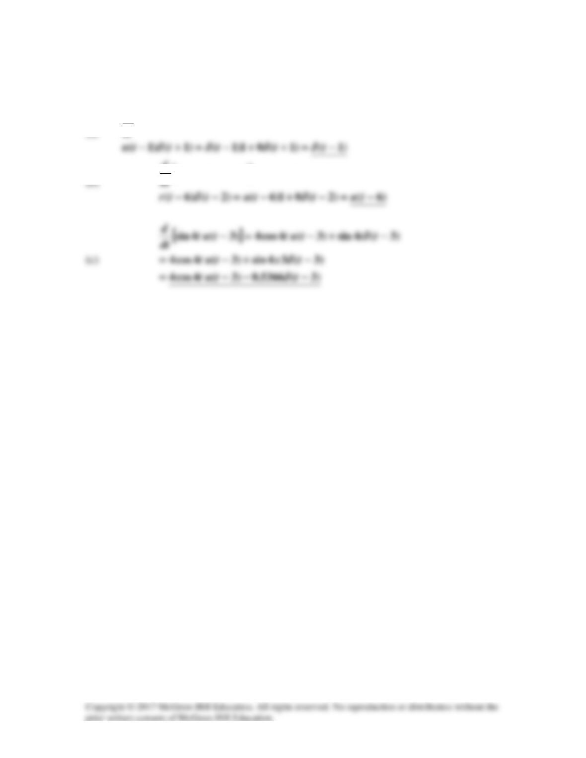
(a)
[ ]
)1()1()1( )1(
++−=+−
tuttutu
dt
d
δ
[ ]
)2()6()2( )6(
+−−=−−
tutututr
d
Solution 7.35
Solution 7.36
(a)
0t,eBA)t(v
-t
>+=
Solution 7.37
Let v = vh + vp, vp =10.
Solution 7.38
Let i = ip +ih