Substituting these into (1) and (2),
s11
s
1111s1s
Zz
V
IIzZIV +
=→=−
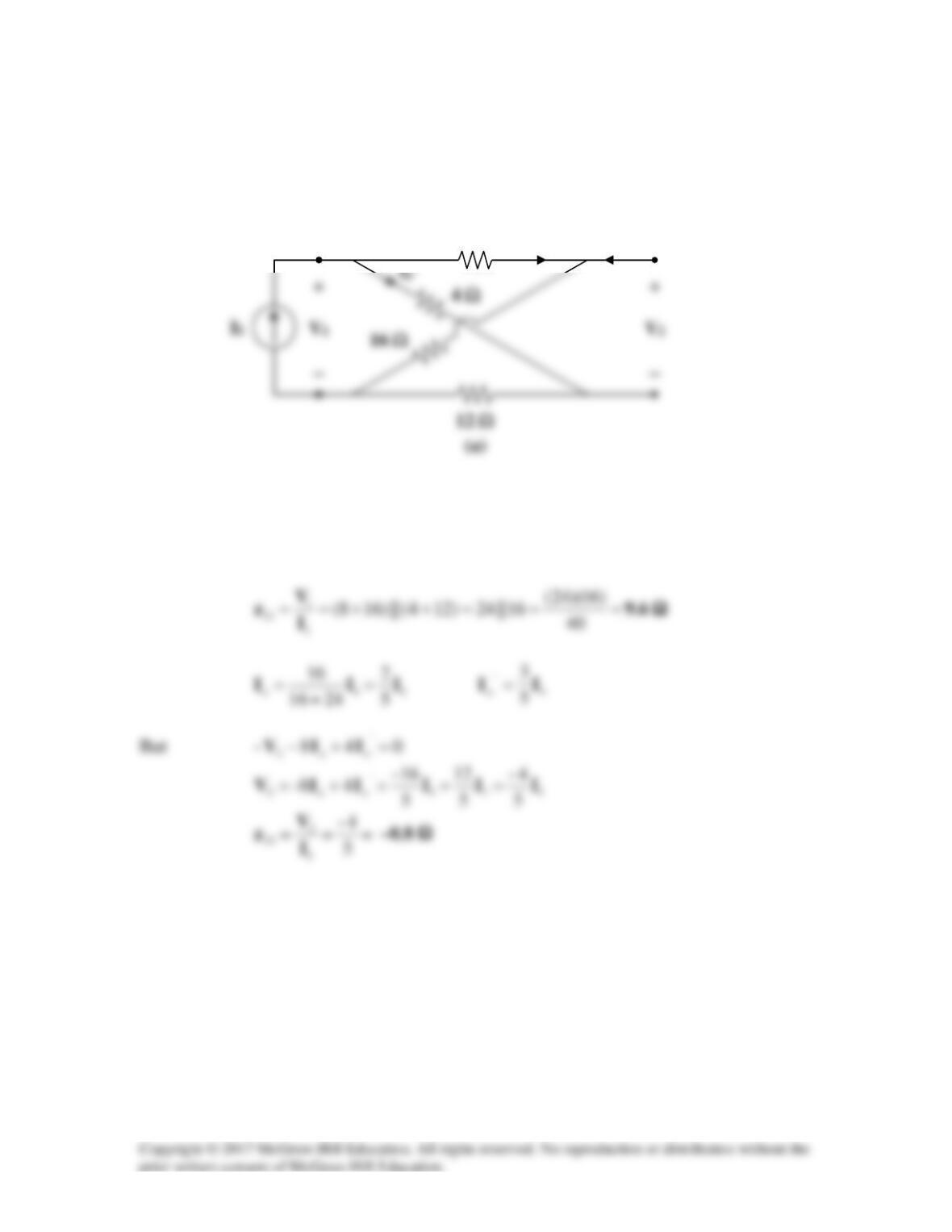
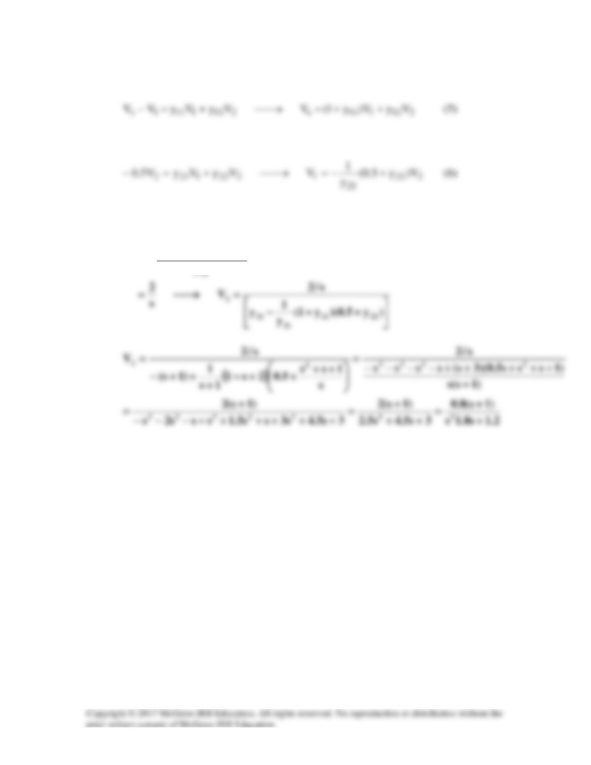
Solution 19.15
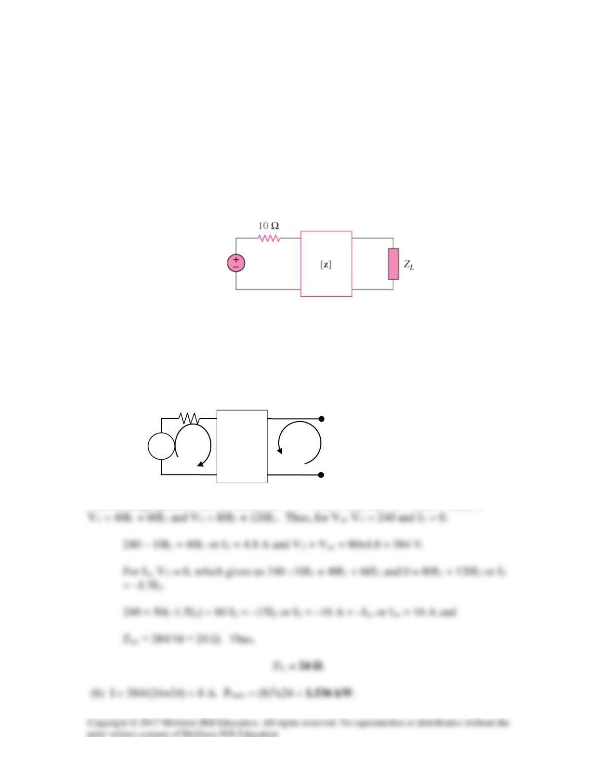
For the two-port circuit in Fig. 19.76,
[ ]
40 60
80 120
z
= Ω
(a). Find ZL for maximum power transfer to the load.
(b). Calculate the maximum power delivered to the load.
Figure 19.76
For Prob. 19.15.
Solution
(a) Since this is just a Thevenin equivalent circuit problem, we need to find Voc and Isc
as seen by ZL.
The defining equations for this circuit are V1 = z11I1+z12I2 and V2 = z21I1 + z22I2 or
240 V rms
VS
+
−
10 Ω
Z
I
1
I2
+
V2
−
+
V1
−
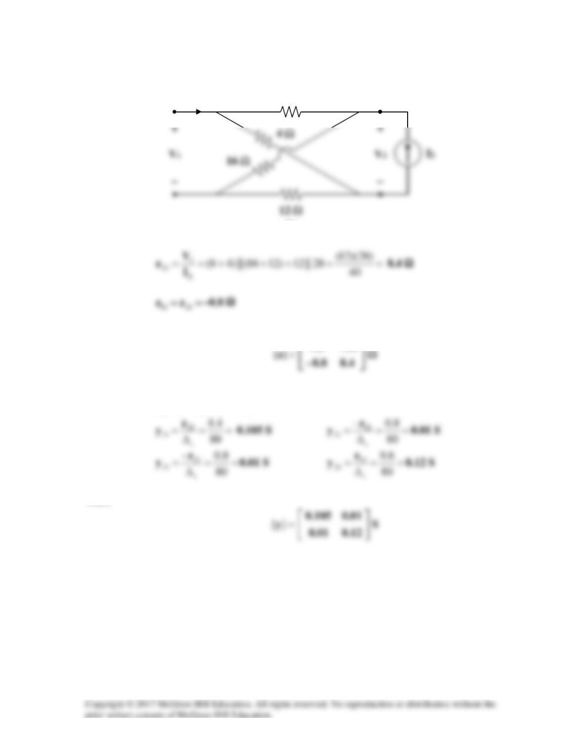
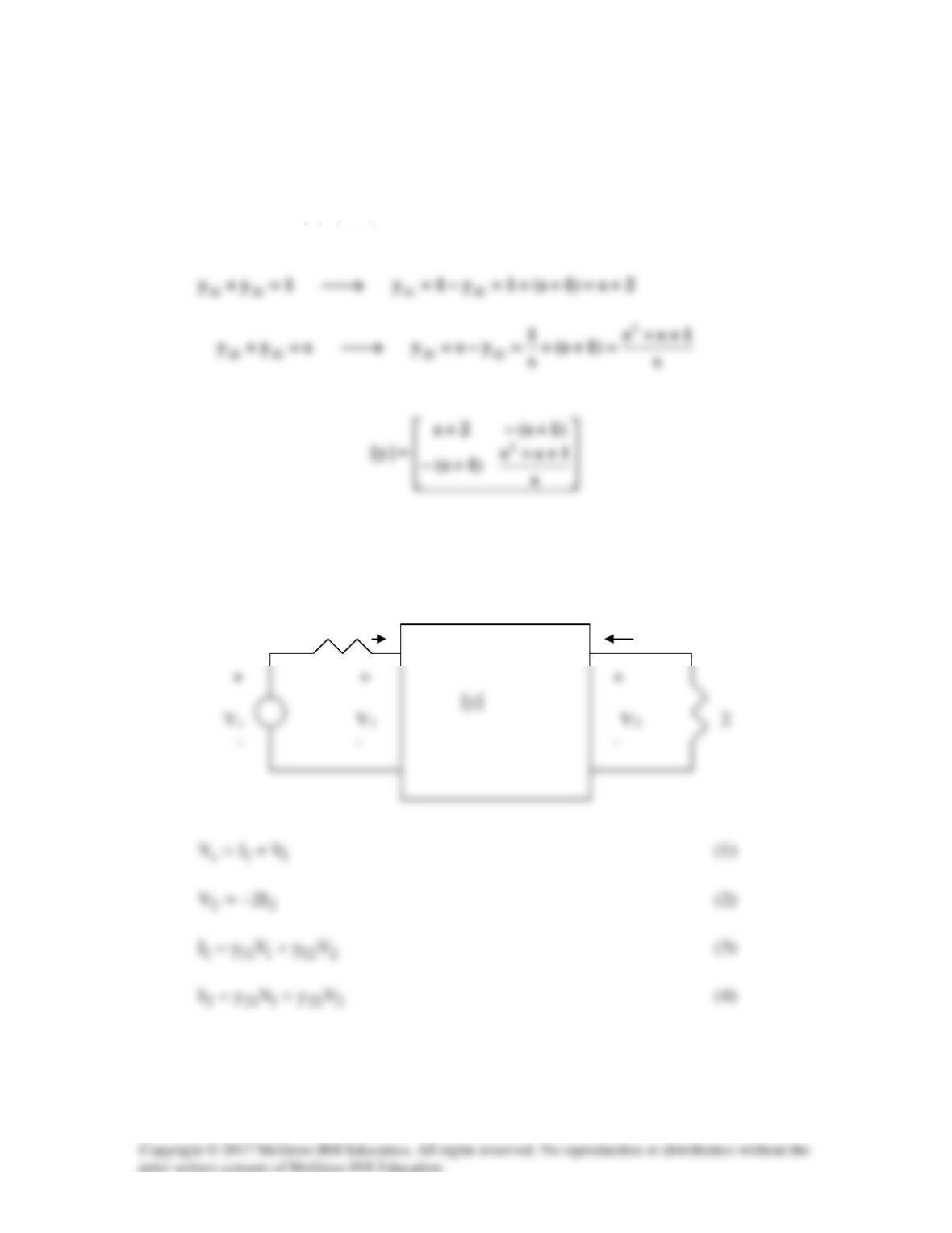
Problem 19.16
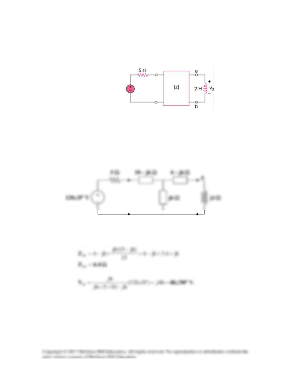
For the circuit in Fig.19.77, at w = 2 rad/s, z11 = 10 Ω, z12 = z21 = j6 Ω, z22 = 4 Ω.
Obtain the Thevenin equivalent circuit at terminals a–b and calculate vo.
Figure 19.77
For Prob. 19.16.
Solution
As a reciprocal two-port, the given circuit can be represented as shown in Fig. (a).
At terminals a-b,
)6j105(||6j)6j4(
Th
−++−=Z
(a)
b
120cos(2t) V
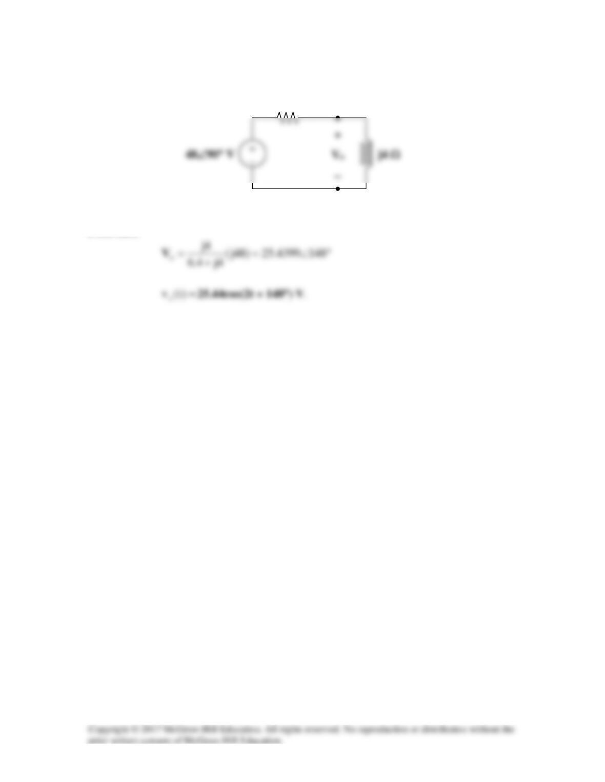
The Thevenin equivalent circuit is shown in Fig. (b).
From this,
6.4 Ω
(b)
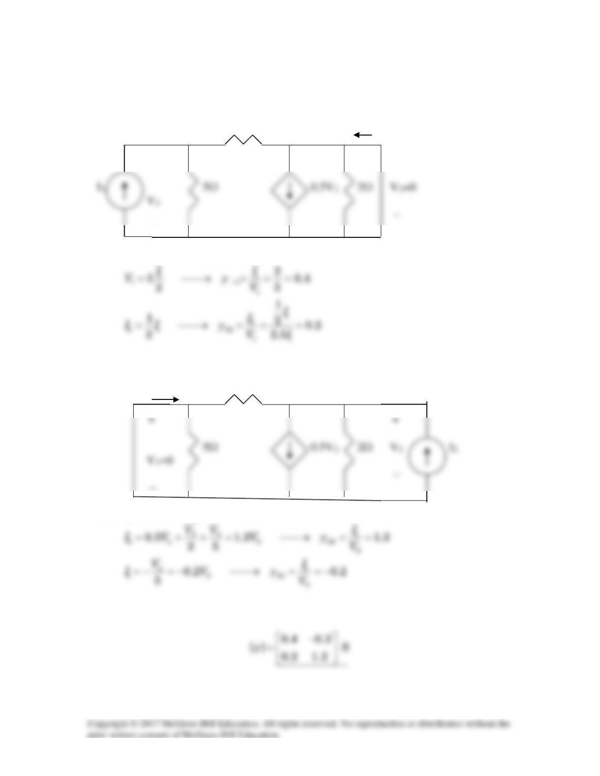
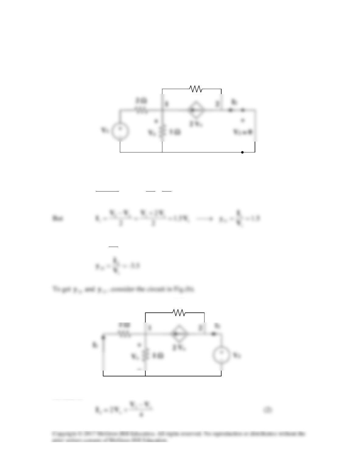
Solution 19.17
To obtain
11
z
and
21
z
, consider the circuit in Fig. (a).
In this case, the 8-Ω and 16-Ω resistors are in series, since the same current,
o
I
, passes
through them. Similarly, the 4-Ω and 12-Ω resistors are in series, since the same current,
‘
o
I
, passes through them.
I2 = 0
8 Ω
Io
To get
22
z
and
12
z
, consider the circuit in Fig. (b).
Thus,
0.8–6.9
We may take advantage of Table 18.1 to get [y] from [z].
80)8.0()4.8)(6.9(
2
=−=∆
z
Thus,
I1 = 0
8 Ω
(b)
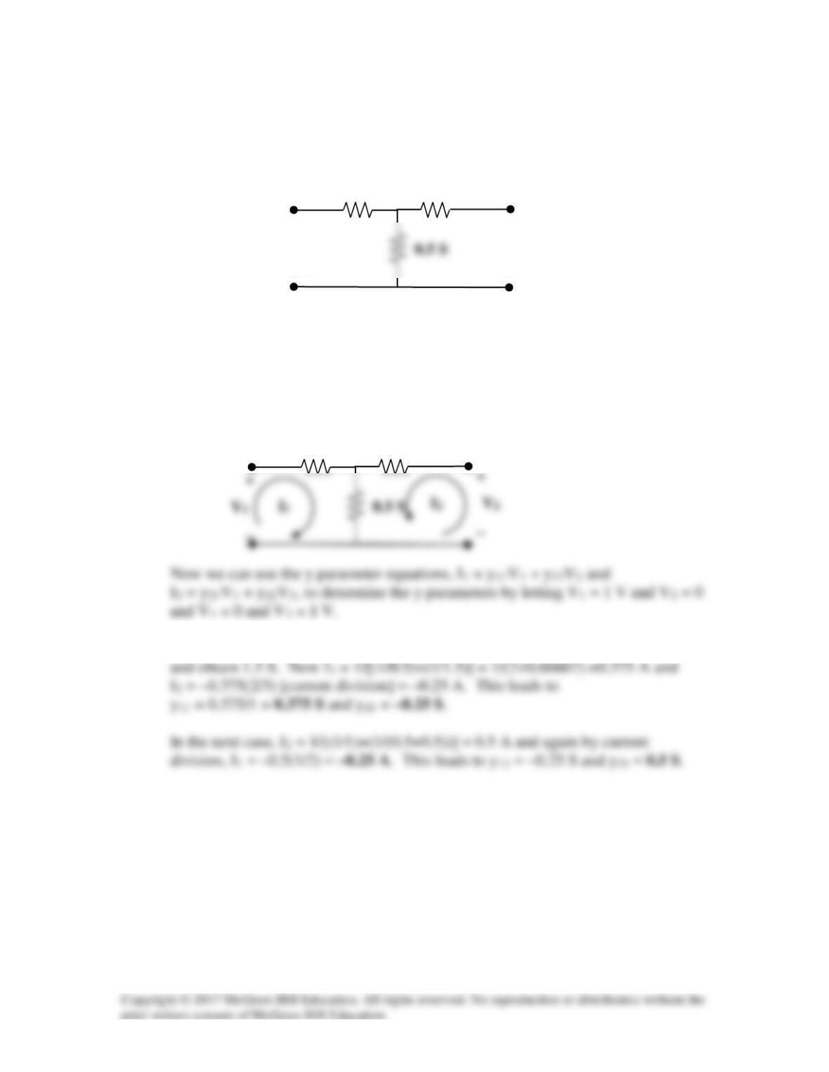
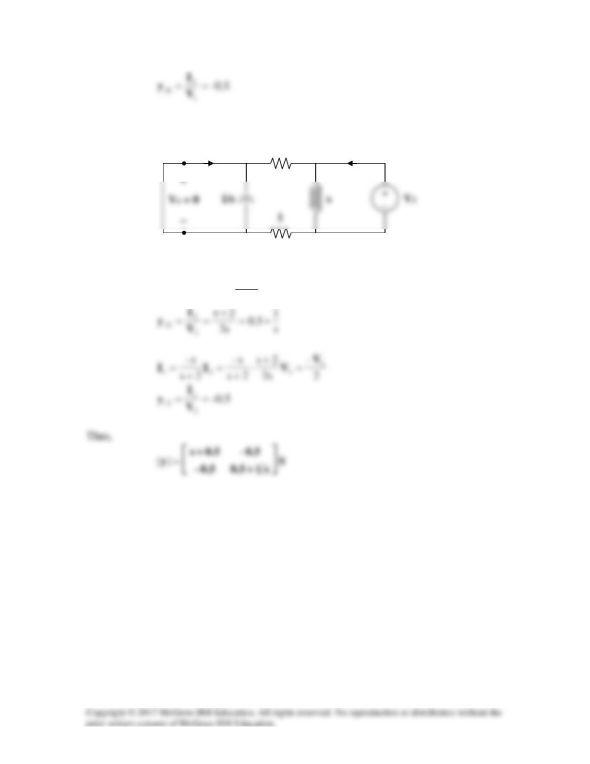
Solution 19.18
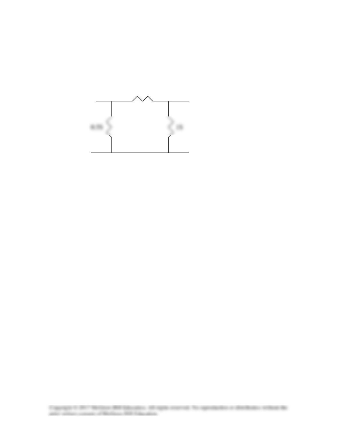
Calculate the y parameters for the two-port in Fig.19.79.
Figure 19.79
For Probs. 19.18 and 19.37.
Solution
Step 1. We first label the circuit so that we can determine the y parameters.
Step 2. Note that we can combine the 1 S resistor in parallel with the 0.5 S resistor
1 S
0.5 S
1 S
0.5 S
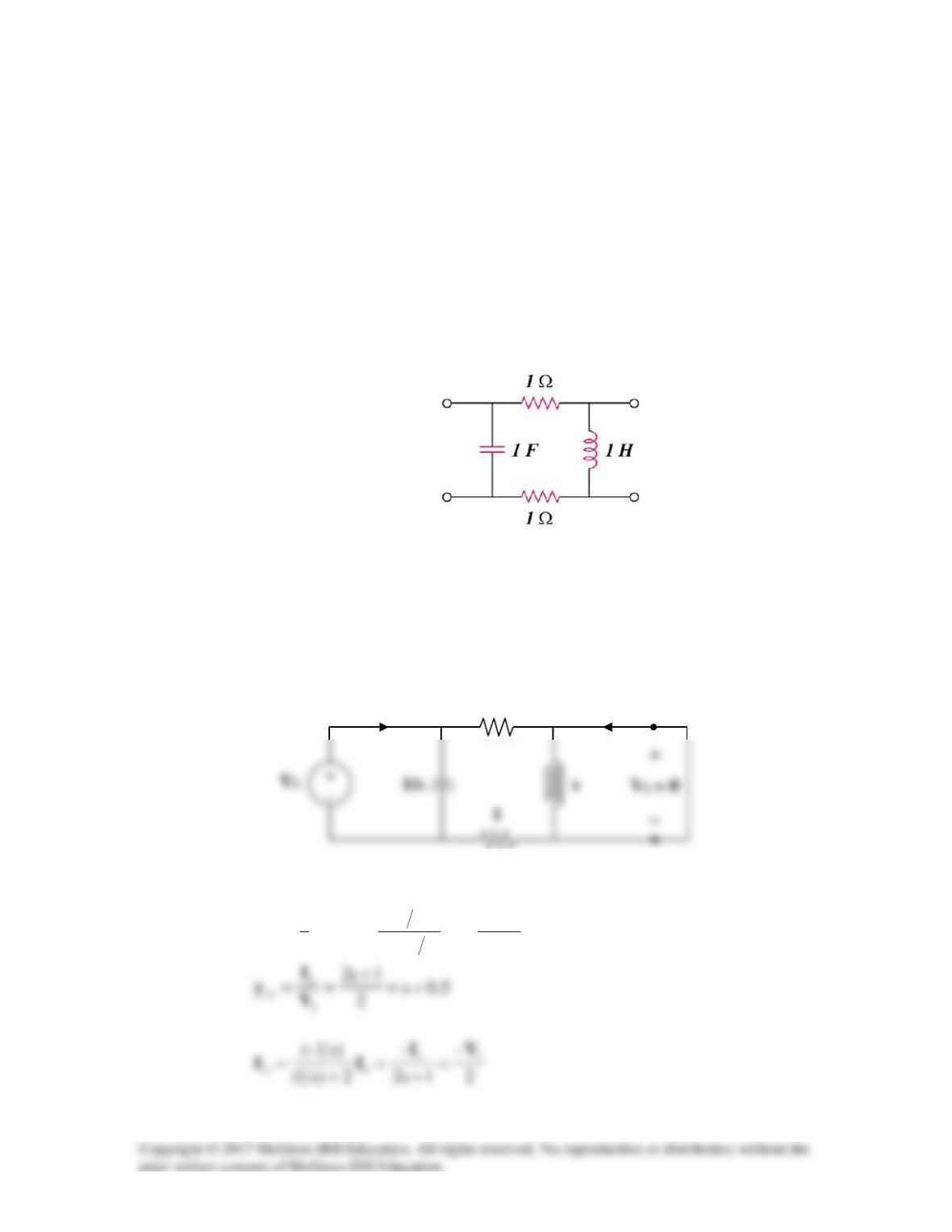
Solution 19.19
Using Fig. 19.80, design a problem to help other students to better understand how to find
y parameters in the s-domain.
Although there are many ways to solve this problem, this is an example based on the
same kind of problem asked in the third edition.
Problem
Find the y parameters of the two-port in Fig.19.80 in terms of s.
Figure 19.80
Solution
Consider the circuit in Fig.(a) for calculating
11
y
and
21
y
.
1111 1s2
2
)s1(2
s2
2||
s
1IIIV +
=
+
=
=
1
(a)
1
I1
I2
To get
22
y
and
12
y
, refer to the circuit in Fig.(b).
222
2s
s2
)2||s( IIV +
==
(b)
I1
I2
1
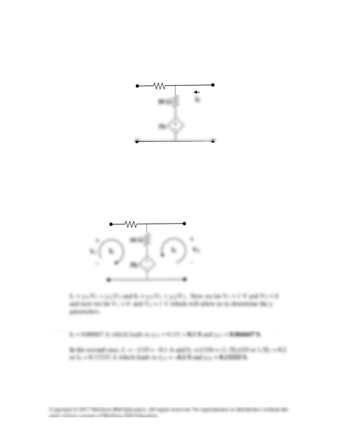
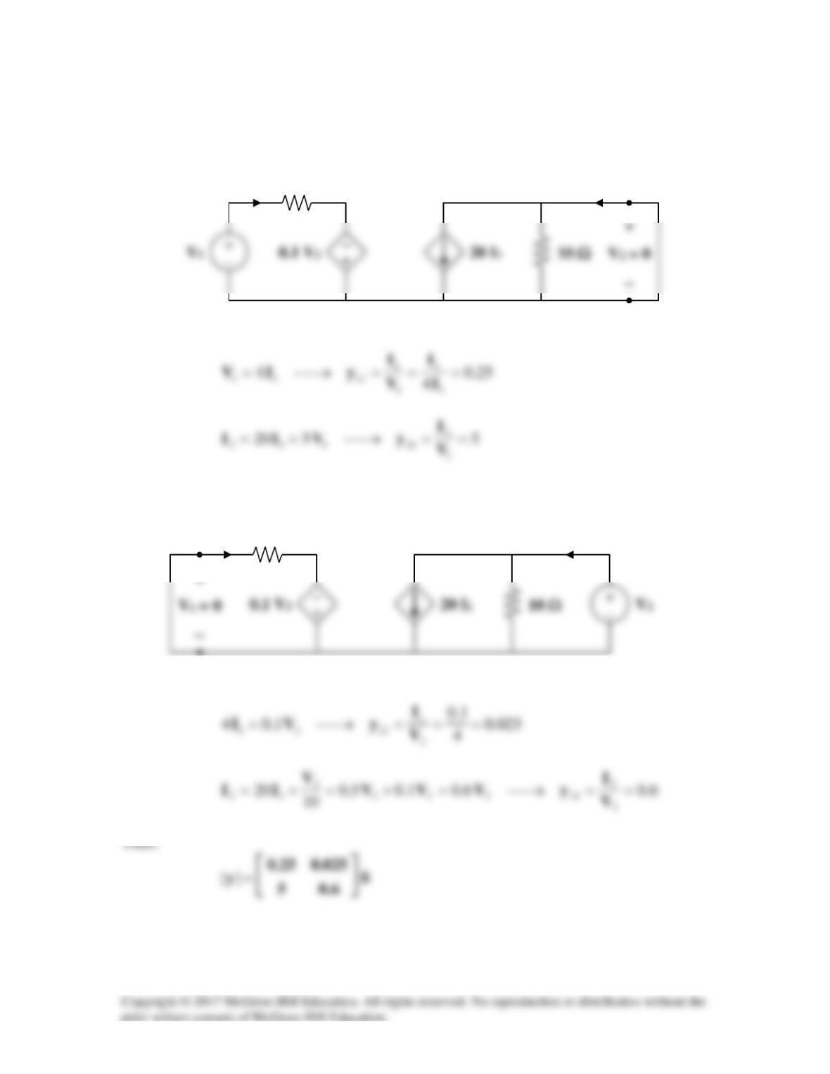
Solution 19.20
Find the y parameters for the circuit in Fig. 19.81.
Figure 19.81
For Prob. 19.20.
Solution
Step 1. We label the circuit with the representative currents and voltages so we can use
the y parameter equations to solve for the y parameters.
Step 2. For the first case I1 = 1/10 = 0.1 A and I2 = 0.1 – 5I2/10 or 1.5I2 = 0.1 or
10 Ω
10 Ω
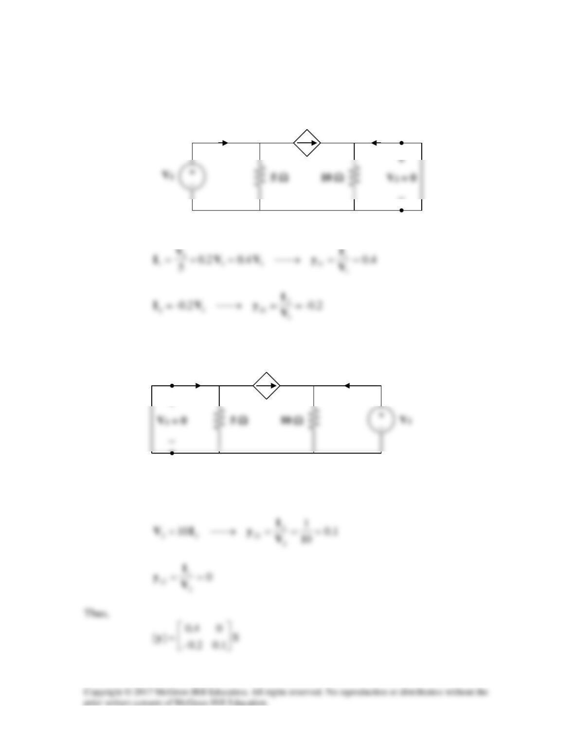
Solution 19.21
To get
11
y
and
21
y
, refer to Fig. (a).
At node 1,
To get
22
y
and
12
y
, refer to the circuit in Fig. (b).
Since
0
1
=V
, the dependent current source can be replaced with an open circuit.
0.2 V1
+
(a)
−
I1
I2
V
1
+
−
I1
I2
0.2 V1
(b)
V1
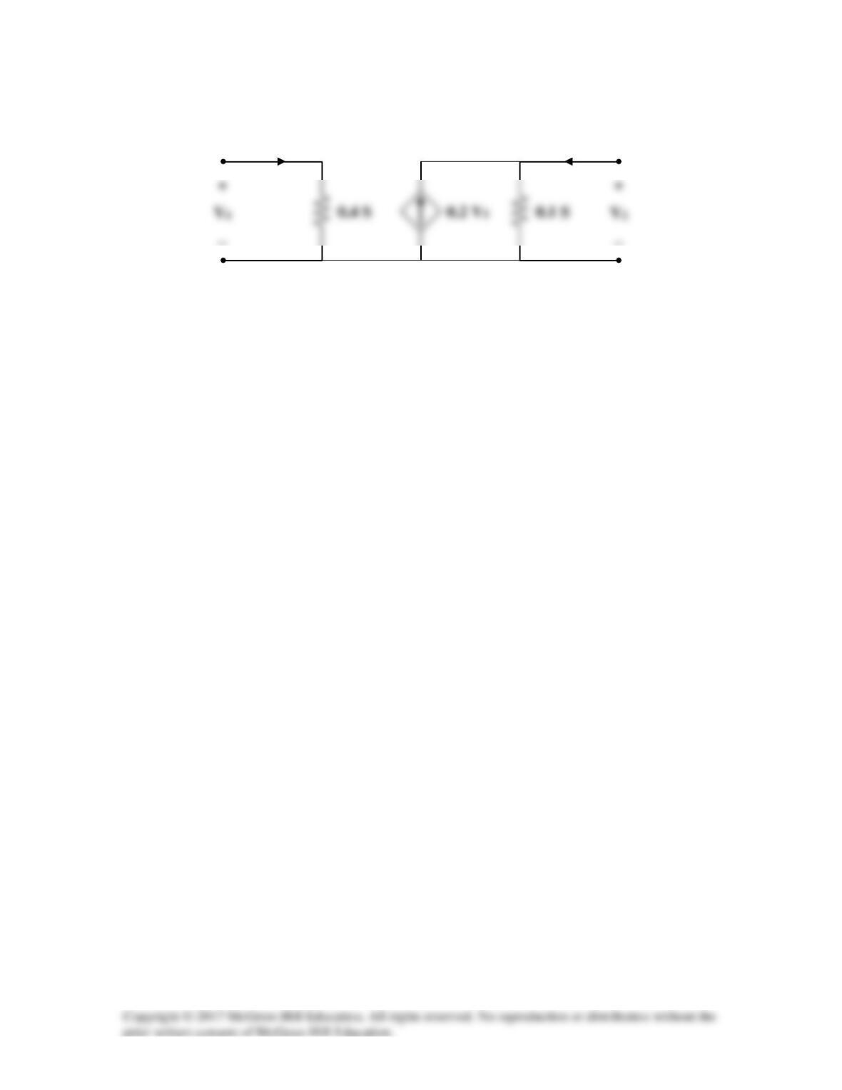
Consequently, the y parameter equivalent circuit is shown in Fig. (c).
−
−
I1
I2
(c)
Solution 19.22
To obtain y11 and y21, consider the circuit below.
5 Ω I2
+ +
–
The 2–Ω resistor is short–circuited.
To obtain y12 and y22, consider the circuit below.
I1 5 Ω
–
At the top node, KCL gives
Hence,
Solution 19.23
(a)
)1s(y
1s
1
s
1
//1)y/(1
1212
+−=→
+
==−
(b) Consider the network below.
I1 I2
1
From (1) and (3)
From (2) and (4),
Substituting (6) into (5),
+
++
−=
VyV
y
)y5.0)(y1(
V
2122
2211
s
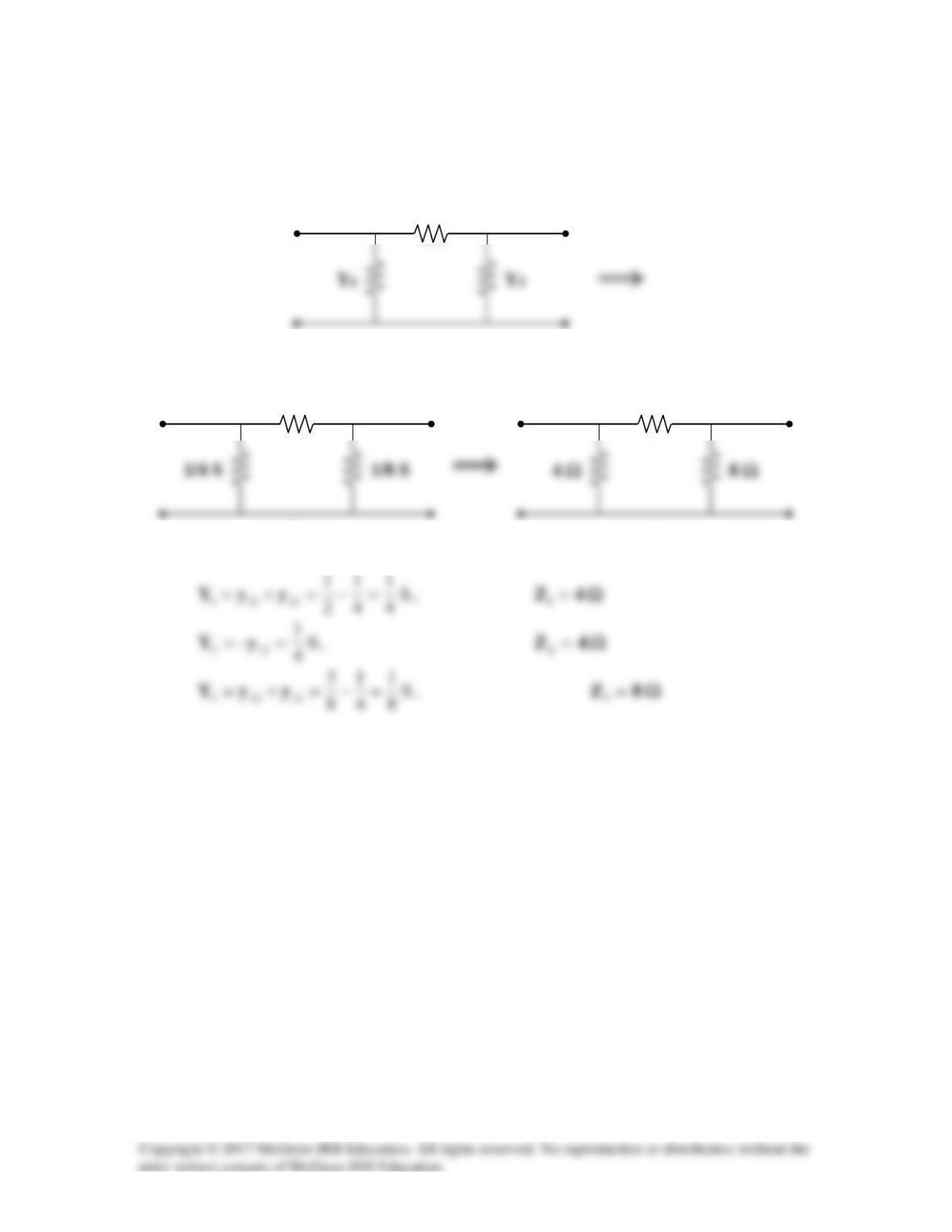
Solution 19.24
Since this is a reciprocal network, a Π network is appropriate, as shown below.
Y2
(a)
1/4 S
(b)
4 Ω
(c)
Solution 19.25
This is a reciprocal network and is shown below.
0.5 S
Solution 19.26
To get
11
y
and
21
y
, consider the circuit in Fig. (a).
At node 1,
x1
xx
x
x1 –2
41
2
2VV
VV
V
VV =→+=+
−
(1)
Also,
1x2x
x
2-3.575.12
4VVIV
V
I==→=+
2 Ω
At node 2,
2 Ω
(a)
−
4 Ω
−
(b)
4 Ω
−
At node 1,
Substituting (3) into (2) gives
Thus,
Solution 19.27
Consider the circuit in Fig. (a).
Consider the circuit in Fig. (b).
(a)
I1
I2
4 Ω
(b)
I1
I2
4 Ω