Solution 7.58
For t < 0,
0)t(v
o
=
Solution 7.59
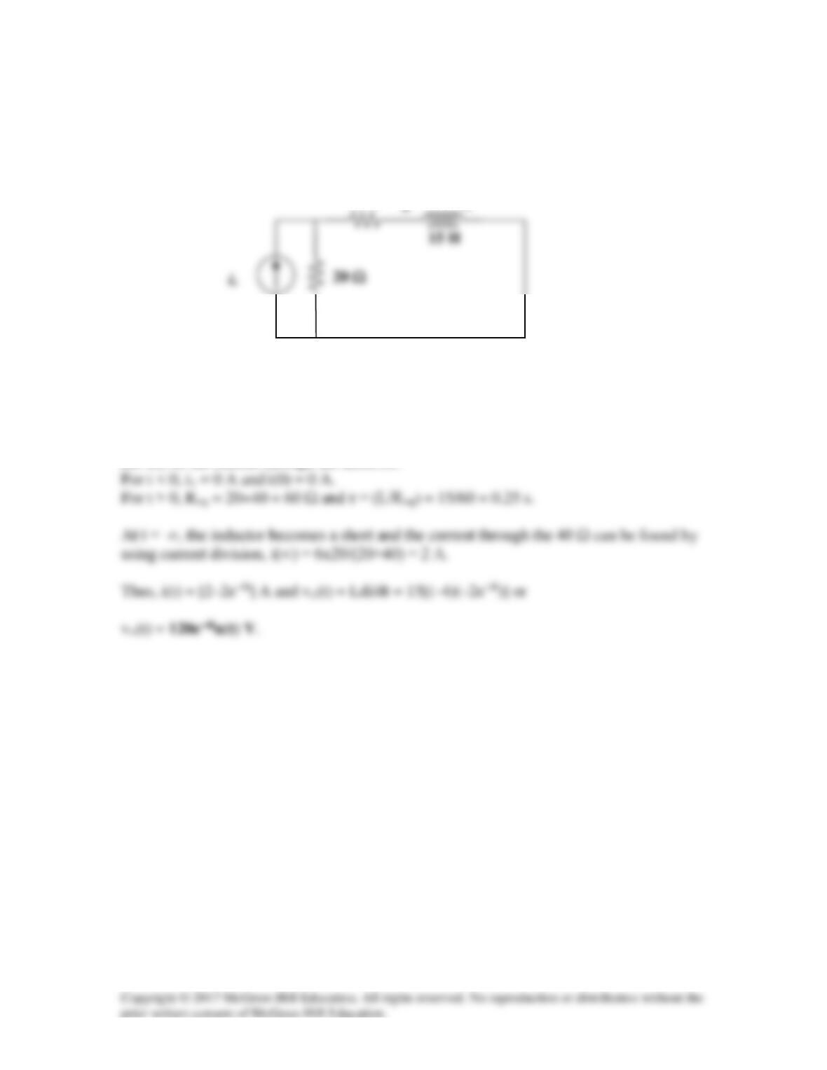
Determine the step response vo(t) to is = 6u(t) A in the circuit of Fig. 7.124.
Figure 7.124
For Prob. 7.59.
Solution
Let i(t) be the current through the inductor.
vo(t)
40 Ω
Solution 7.60
Let I be the inductor current.
Solution 7.61
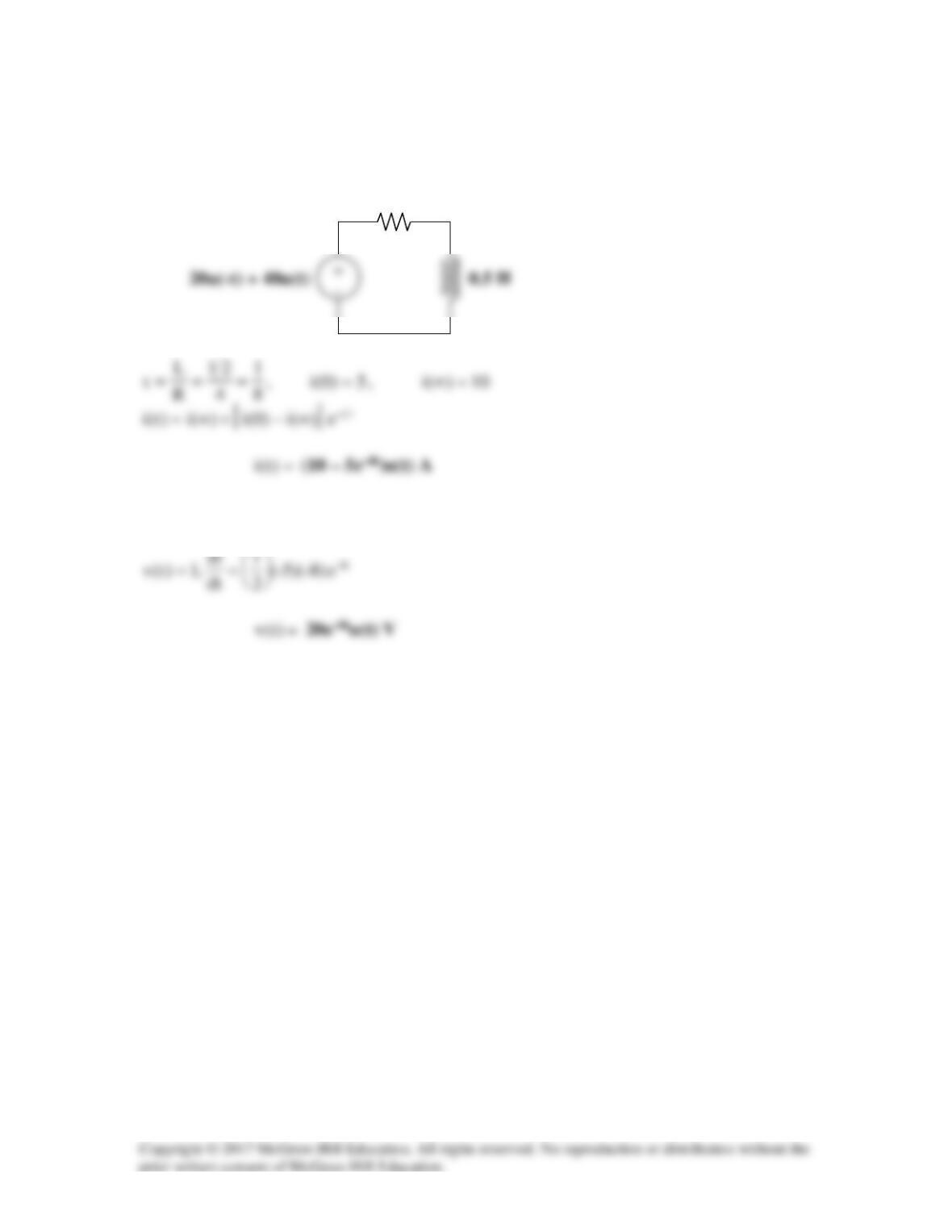
The current source is transformed as shown below.
4 Ω
Solution 7.62
1
6||3
2
R
L
eq
===τ
For t > 1,
( )
1054.0e1
6
1
)1(i 1– =−=
Thus,
Solution 7.63
For t < 0,
1)t–(u =
,
2
5
10
)0(i ==
Solution 7.64
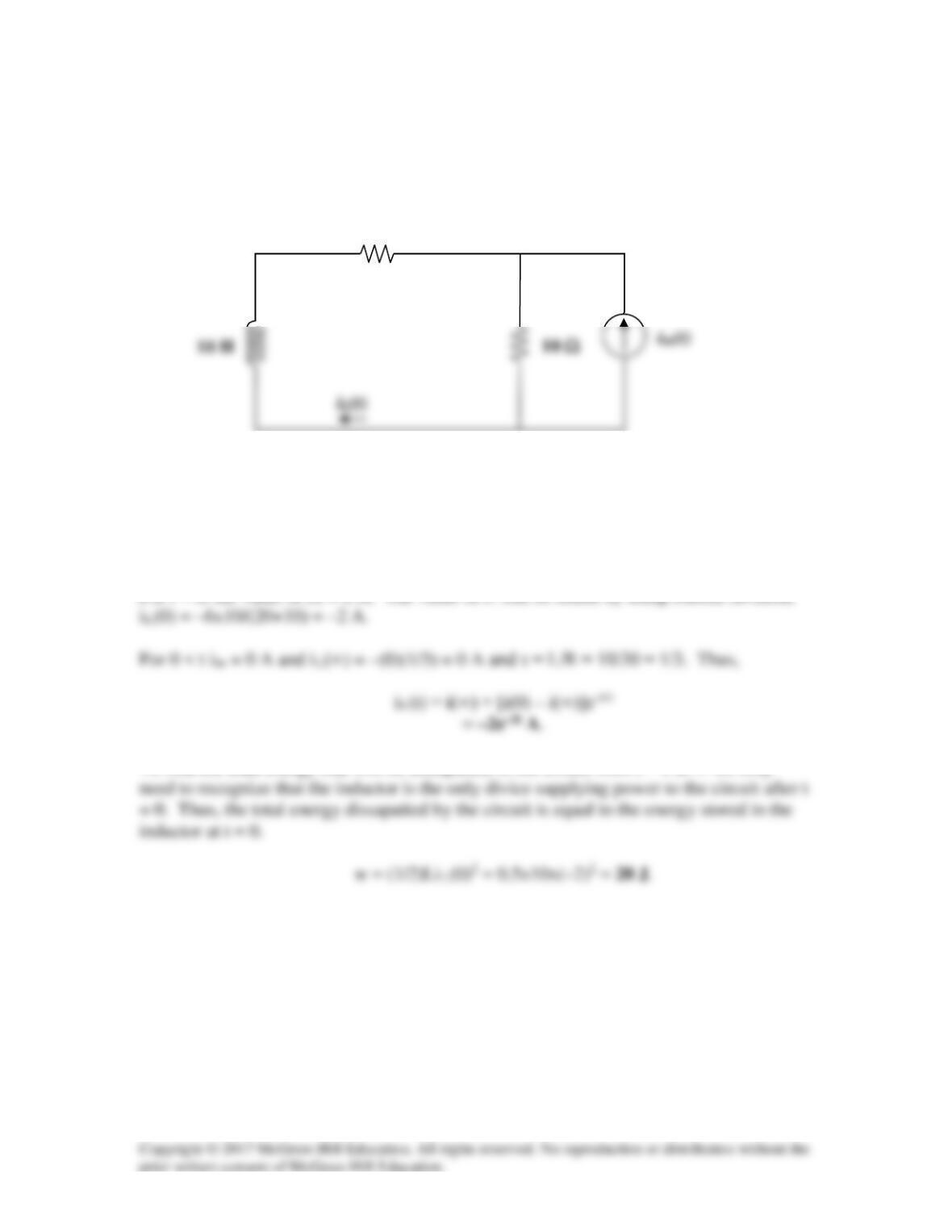
Determine the value of iL(t) and the total energy dissipated by the circuit from
t = 0 sec to t = ∞ sec. The value of iin(t) is equal to [6 – 6u(t)] A.
Figure 7.129
For Prob. 7.64.
Solution
For t < 0, the value of iin = 6 A. The value of iL can be found by using current division,
To find the total energy that will be dissapaited in the circuit from t = 0 to ∞ we only
20 Ω
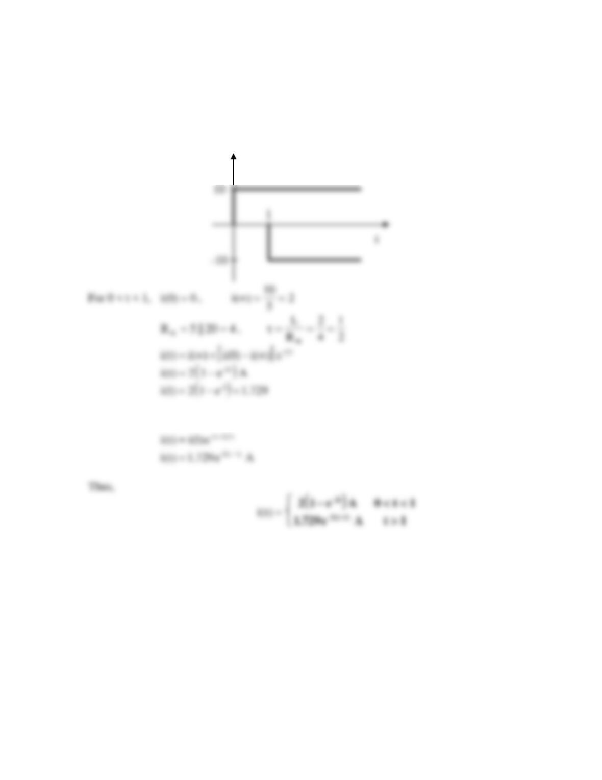
Solution 7.65
Since
[ ]
)1t(u)t(u10vs−−=
, this is the same as saying that a 10 V source is turned on at
t = 0 and a -10 V source is turned on later at t = 1. This is shown in the figure below.
For t > 1,
0)(i =
∞
since
0v
s
=
vs
Solution 7.66
Using Fig. 7.131, design a problem to help other students to better understand first-order
Problem
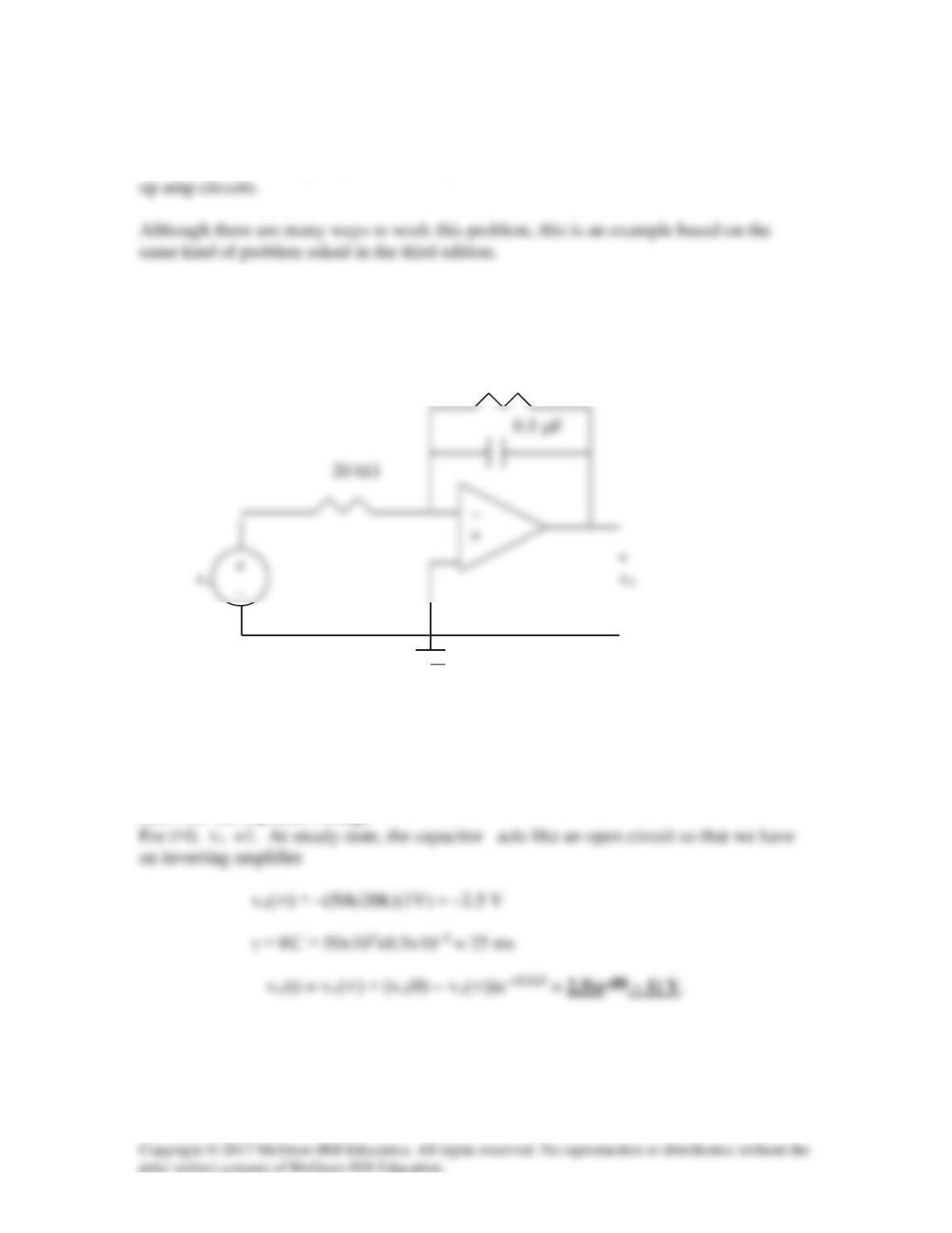
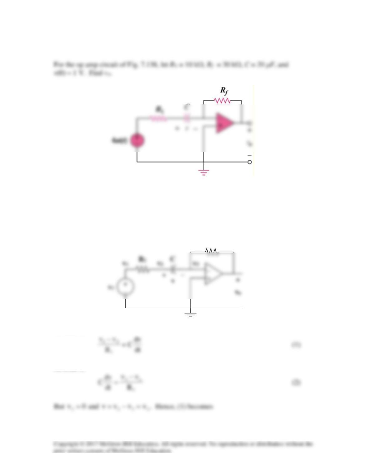
For the op-amp circuit of Fig. 7.131, find vo. Assume that vs changes abruptly from 0 to
1 V at t=0. Find vo.
50 kΩ
–
Figure 7.131 For Prob. 7.66.
Solution
For t<0-, vs =0 so that vo(0)=0
:Let v be the capacitor voltage
Solution 7.67
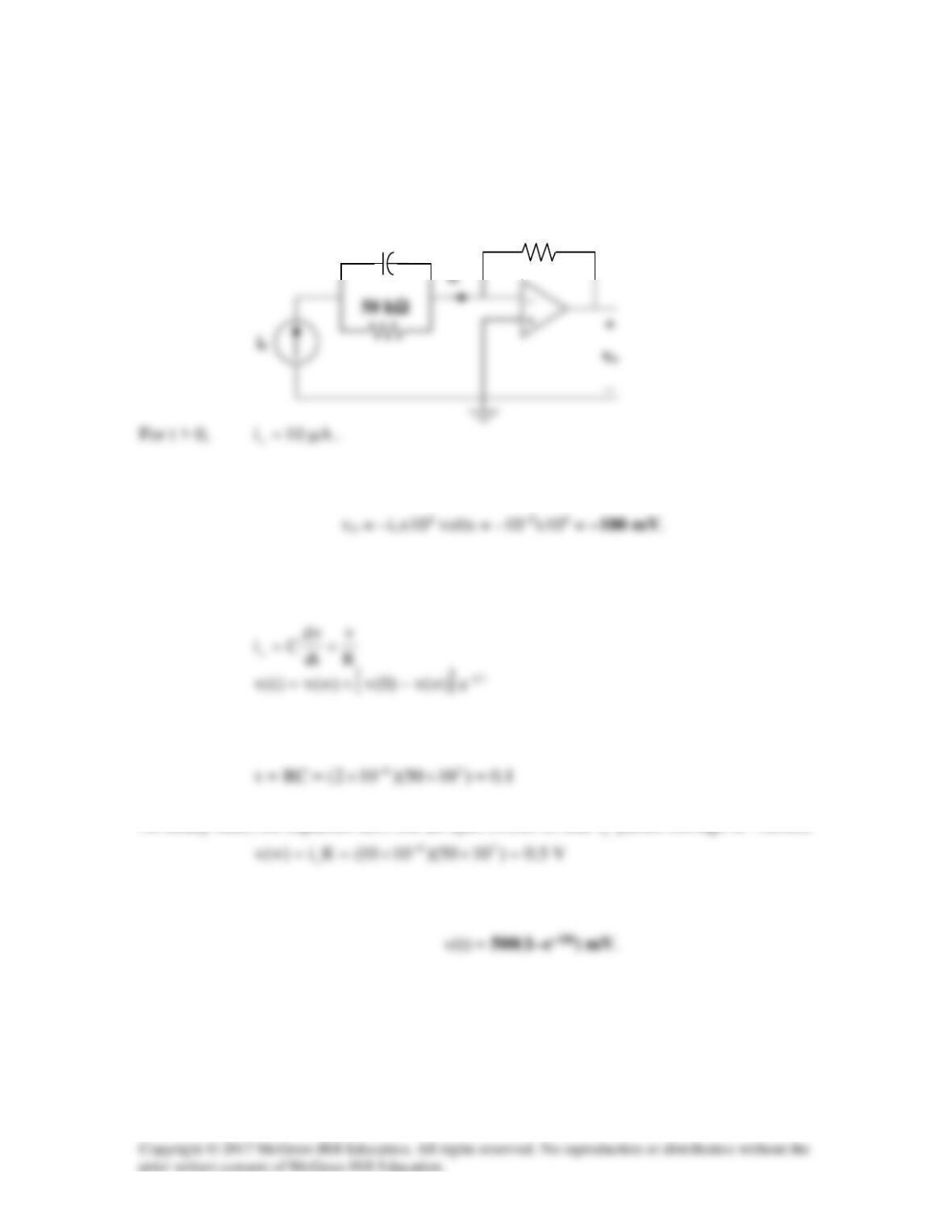
If v(0) = 10 V, find vo(t) for t > 0 in the op amp circuit in Fig. 7.132.
Let R = 100 kΩ and C = 20 µF.
Figure 7.132
For Prob. 7.67.
Solution
In this circuit, the resistor between the capacitor and the positive input terminal of the op
amp can be neglected since the current through it has to be equal to zero. This then
−
Solution 7.68
This is a very interesting problem which has both an ideal solution as well as a realistic
solution. Let us look at the ideal solution first. Just before the switch closes, the value of
the voltage across the capacitor is zero which means that the voltage at both terminals
input of the op amp are each zero. As soon as the switch closes, the output tries to go to a
voltage such that both inputs to the op amp go to 4 volts. The ideal op amp puts out
whatever current is necessary to reach this condition. An infinite (impulse) current is
necessary if the voltage across the capacitor is to go to 8 volts in zero time (8 volts across
the capacitor will result in 4 volts appearing at the negative terminal of the op amp). So
vo will be equal to 8 volts for all t > 0.
What happens in a real circuit? Essentially, the output of the amplifier portion of the op
amp goes to whatever its maximum value can be. Then this maximum voltage appears
across the output resistance of the op amp and the capacitor that is in series with it. This
results in an exponential rise in the capacitor voltage to the steady-state value of 8 volts.
Solution 7.69
Let
v
be the capacitor voltage.
For t > 0, the 20 kΩ and 100 kΩ resistors are in series and together, they are in parallel
with the capacitor since no current enters the op amp terminals. As
∞→t
, the capacitor
acts like an open circuit so that
Solution 7.70
Let v = capacitor voltage.
For t < 0, the switch is open and
0)0(v =
.
From (1),
0
RC
v
dt
dv
s
==
Since v is constant,
1.0)105)(1020(RC -63=××=
From (3),
R
C
Solution 7.71
20 kΩ
100 kΩ
Figure 7.136
For Prob. 7.71.
Solution
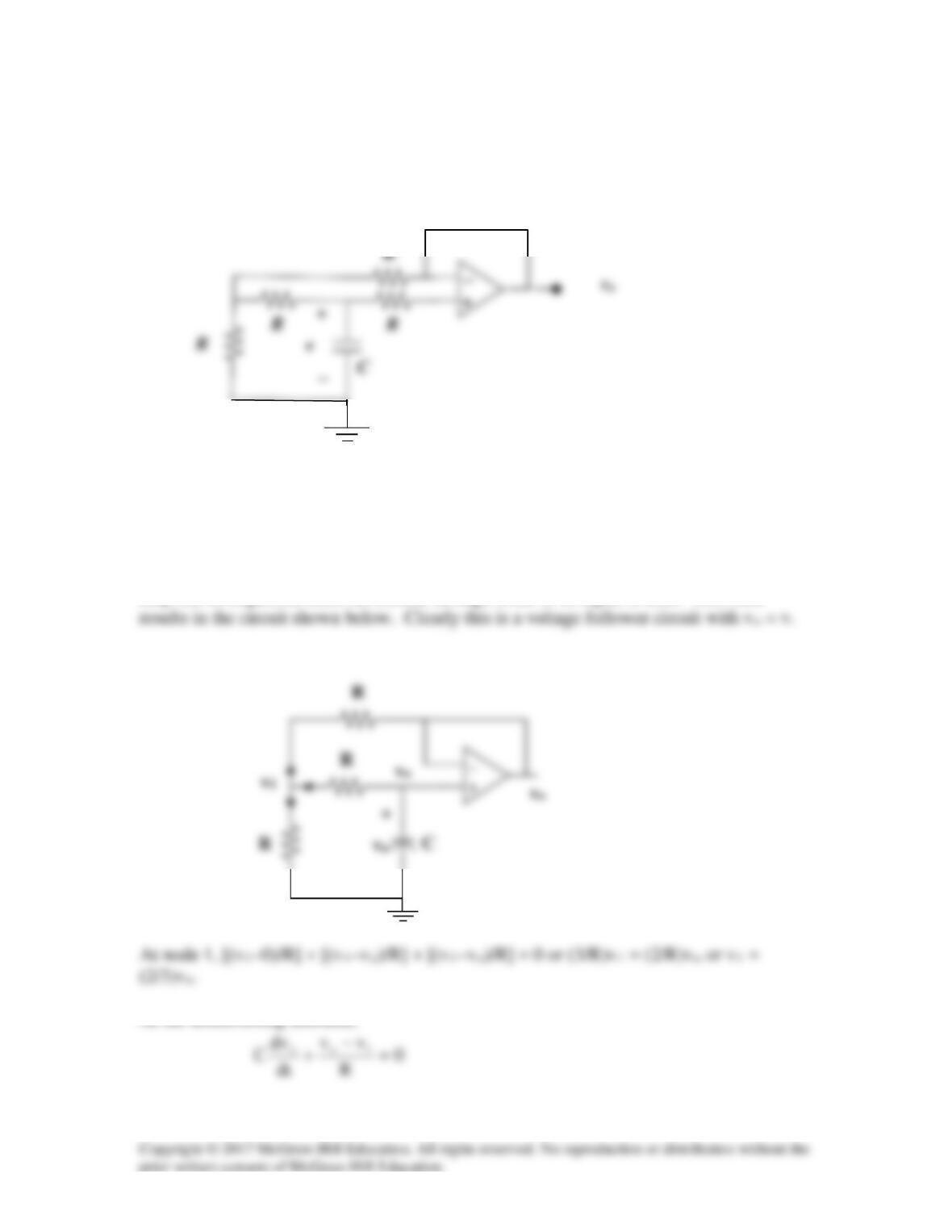
We recognize that the op amp operates as an inverting op amp whose output is equal to –
vs = –10u(t) V. Since the output of the op amp acts like an ideal voltage source, we can
100 kΩ
−
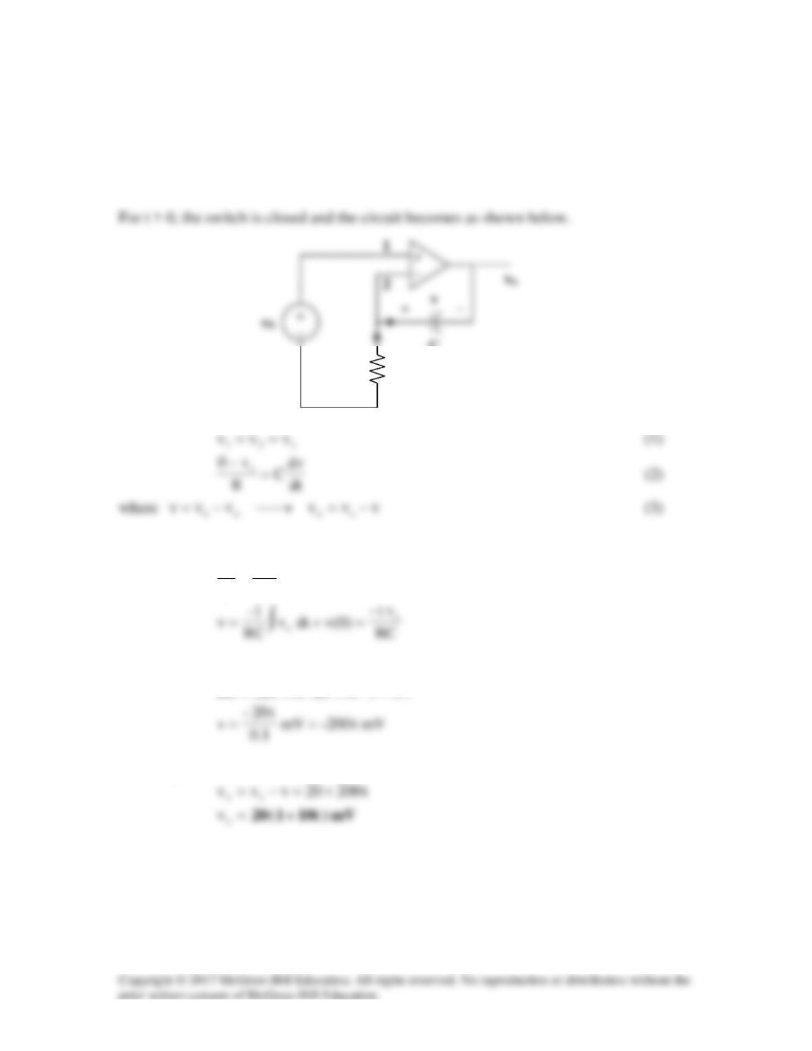
Solution 7.72
The op amp acts as an emitter follower so that the Thevenin equivalent circuit is shown
below.
Hence,
[ ]
τ
∞−+∞= t–
e)(v)0(v)(v)t(v
C
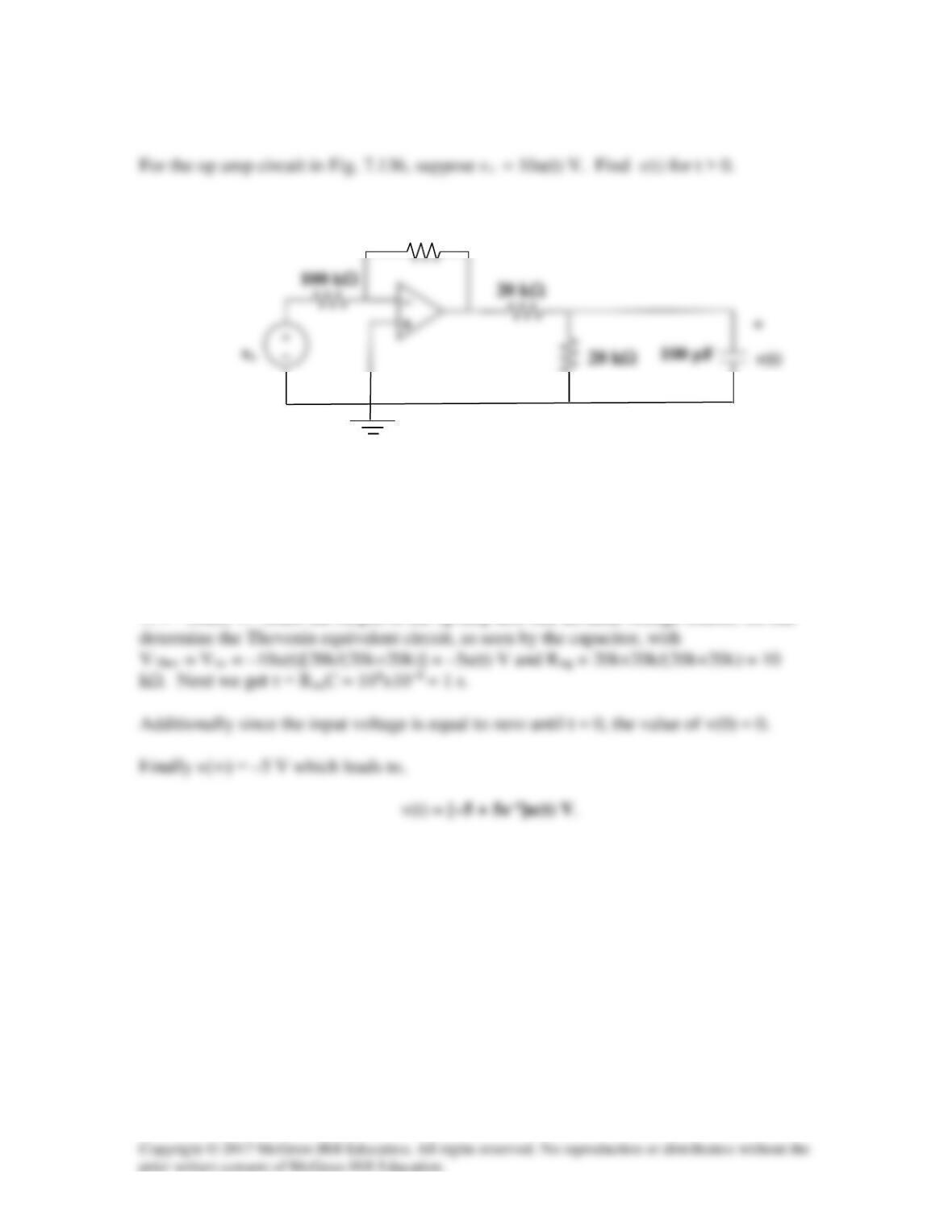
Solution 7.73
Figure 7.138
For Prob. 7.73.
Solution
Consider the circuit below.
At node 2,
At node 3,
Rf
−
1
1
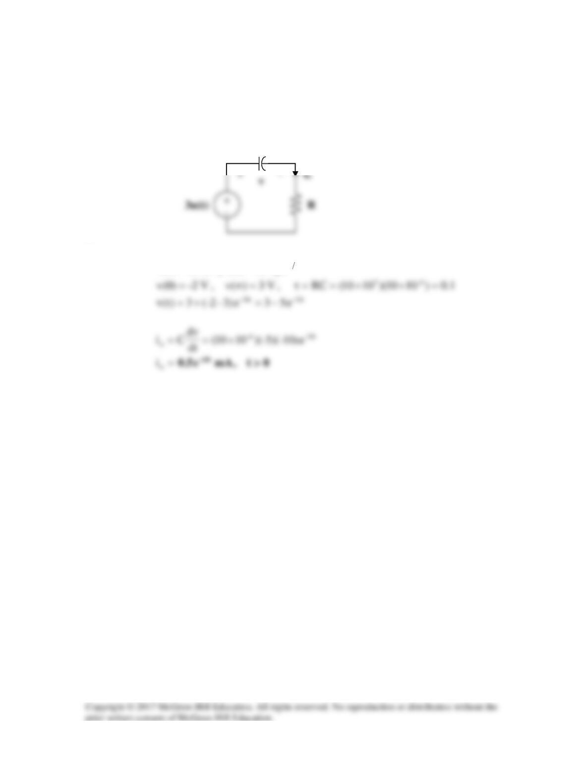
which is similar to Eq. (7.42). Hence,
where
1)0(vvT==
and
4v1=
From (2),
Solution 7.74
Let v = capacitor voltage. For t < 0,
0)0(v =
50 kΩ
Since the current through the feedback resistor is is, then
It is interesting to look at the capacitor voltage.
It is evident that
At steady state, the capacitor acts like an open circuit so that
i
passes through R. Hence,
Then the voltage across the capacitor is,
10 kΩ
2 µF