Solution 5.39
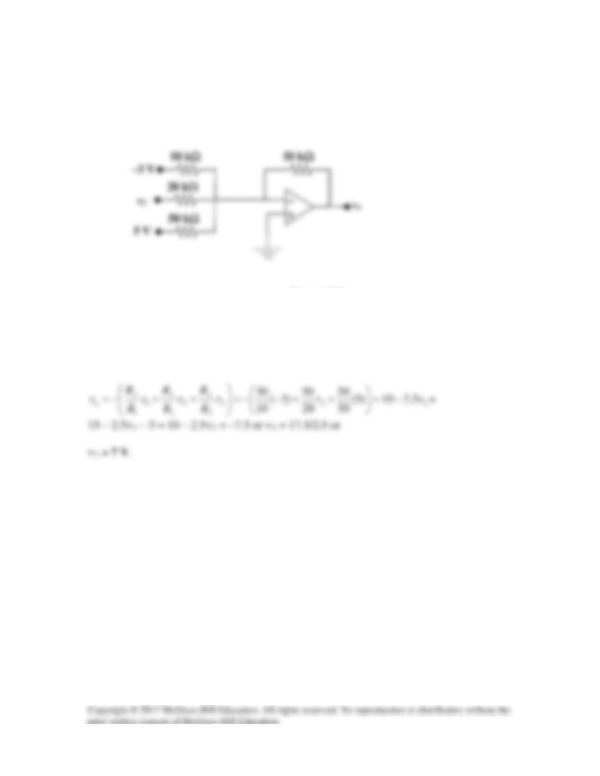
For the op amp circuit in Fig. 5.76, determine the value of v2 in order to make
vo = –7.5 V.
Figure 5.76
For Prob. 5.39.
Solution
This is a summing amplifier.
Solution 5.40
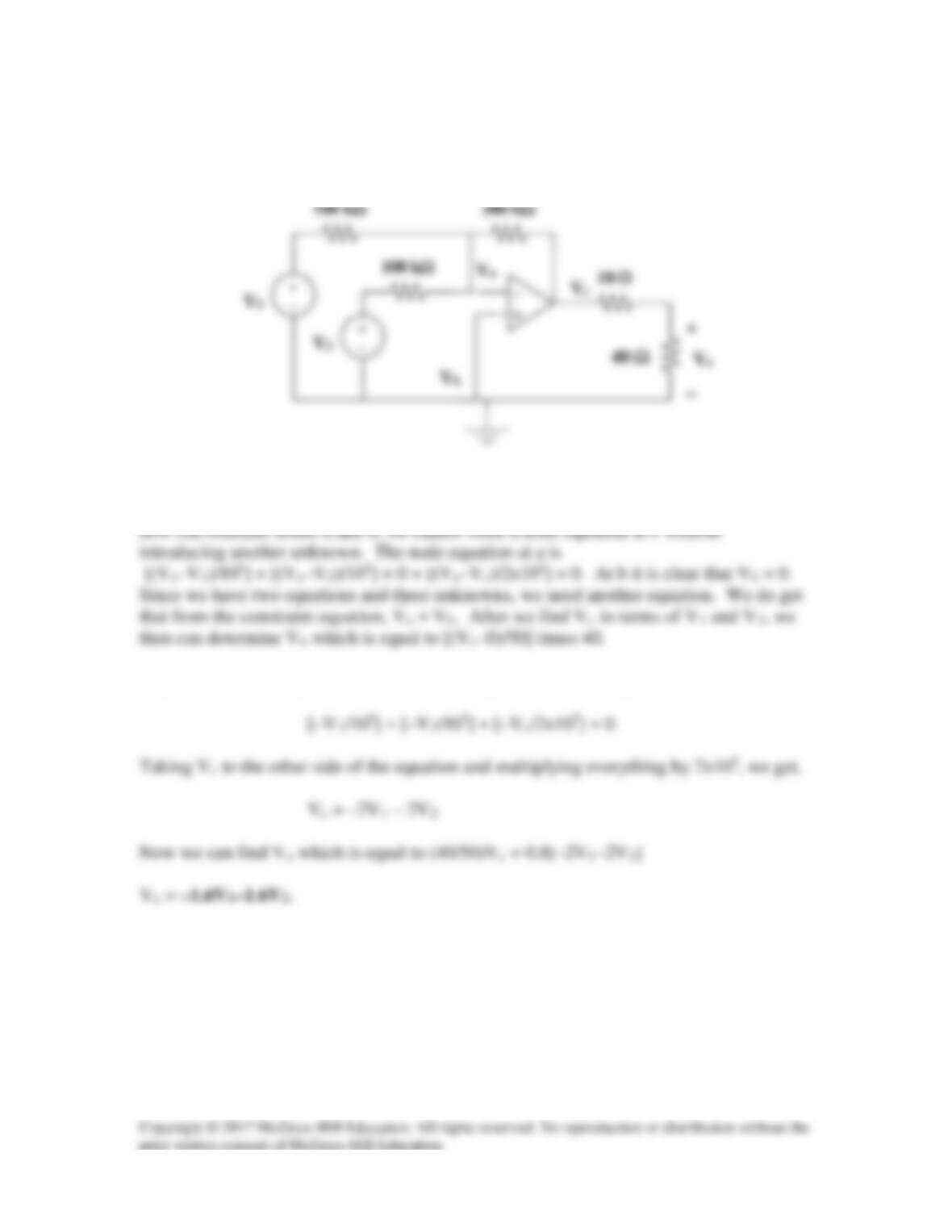
Determine Vo in terms of V1 and V2.
Step 1. Label the reference and node voltages in the circuit, see above. Note we
Step 2. Letting Va = Vb = 0, the first equation can be simplified to,
Solution 5.41
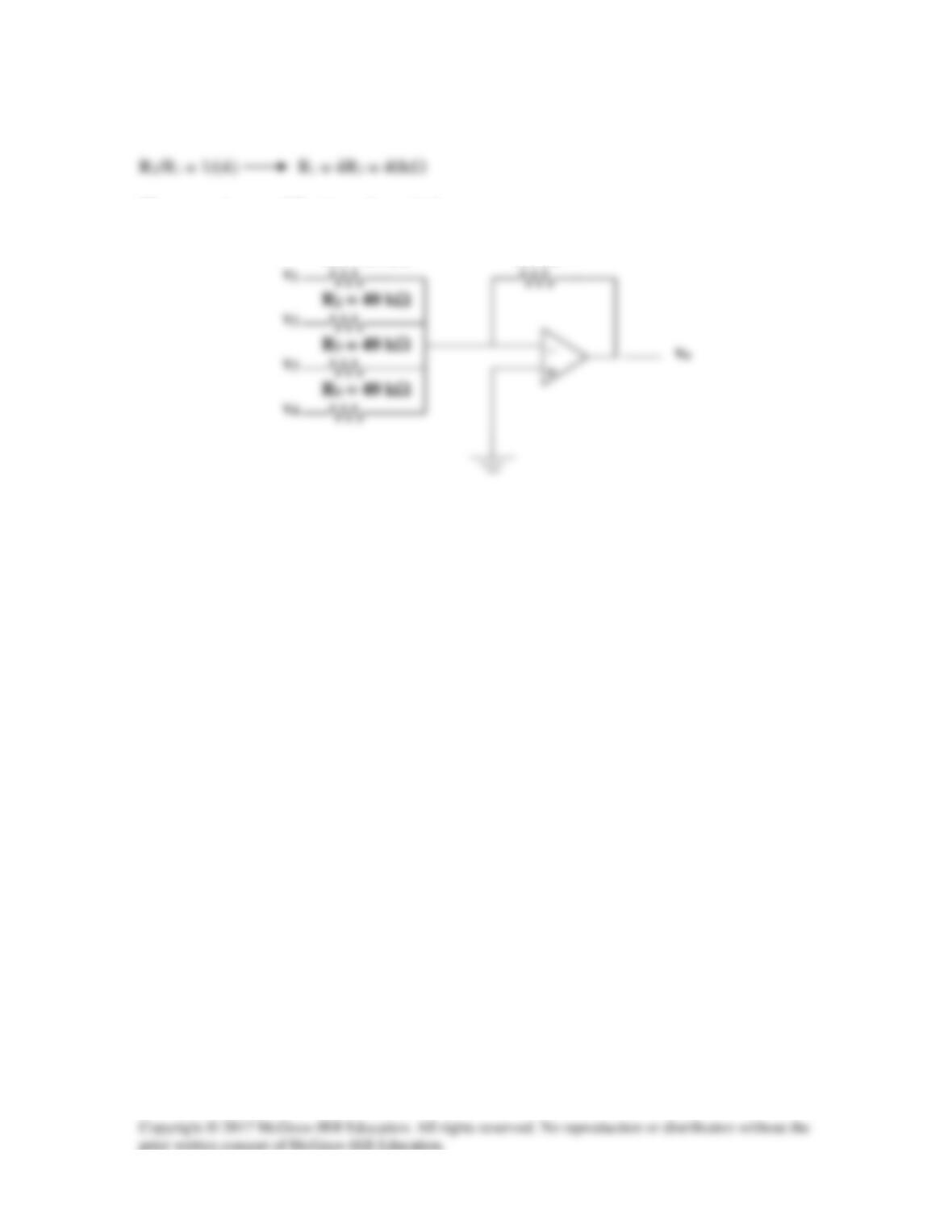
The averaging amplifier is as shown below:
R4 = 40 kΩ
R3 = 40 kΩ
R2 = 40 kΩ
10 kΩ
R1 = 40 kΩ
Solution 5.42
The feedback resistor of a three–input averaging summing amplifier is 50 kΩ. What are
the values of R1, R2, and R3?
Solution
Since the average of three numbers is the sum of those numbers divided by three, the
Solution 5.43
The feedback resistor of a five-input averaging summing amplifier is 40 kΩ. What are
the values of R1, R2, R3, R4, and R5?
Solution
In order to find the average of five inputs each input resistor needs to be five times the
Solution 5.44
R2
R1
R4
R3
a
Solution 5.45
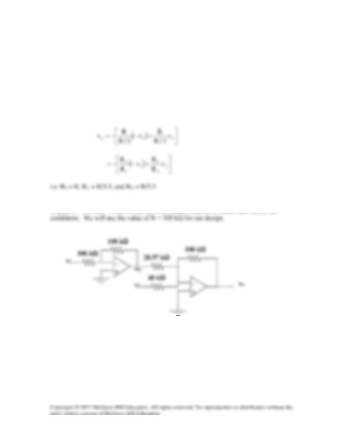
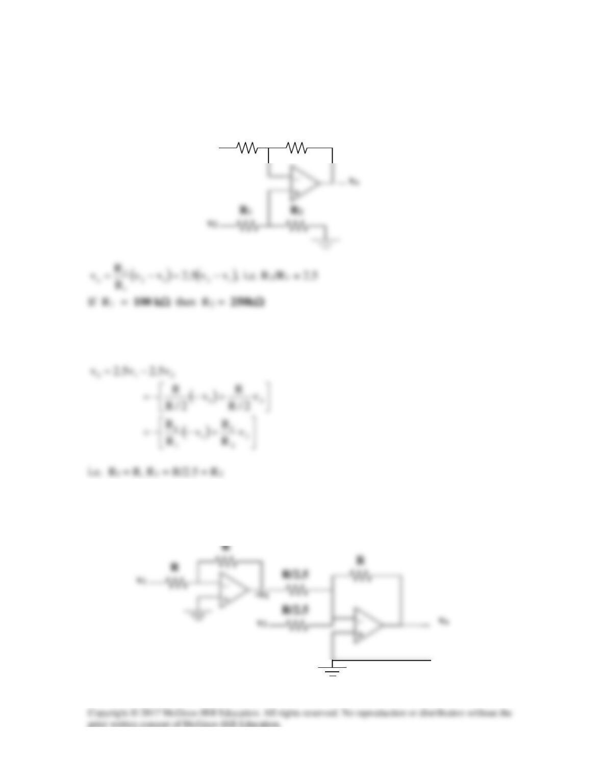
Design an op amp circuit to perform the following operation:
vo = 3.5v1 – 2.5v2
All resistances must be ≤ 100 kΩ.
Solution
This can be achieved as follows:
Thus we need an inverter to invert v1, and a summer, as shown below (R≤100kΩ). Let
us pick R = 100 kΩ. Note, we can have an infinite number of values that satisfy the
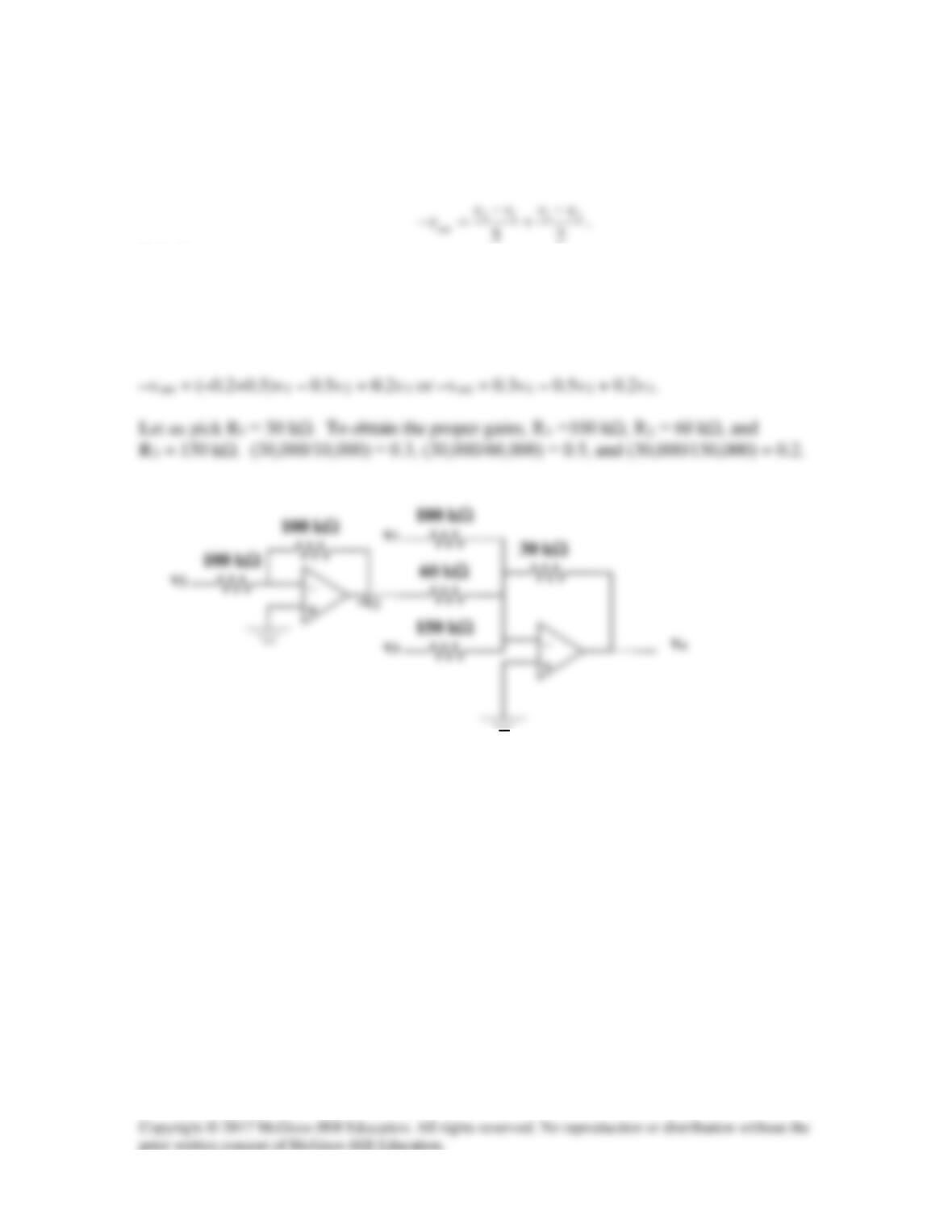
Solution 5.46
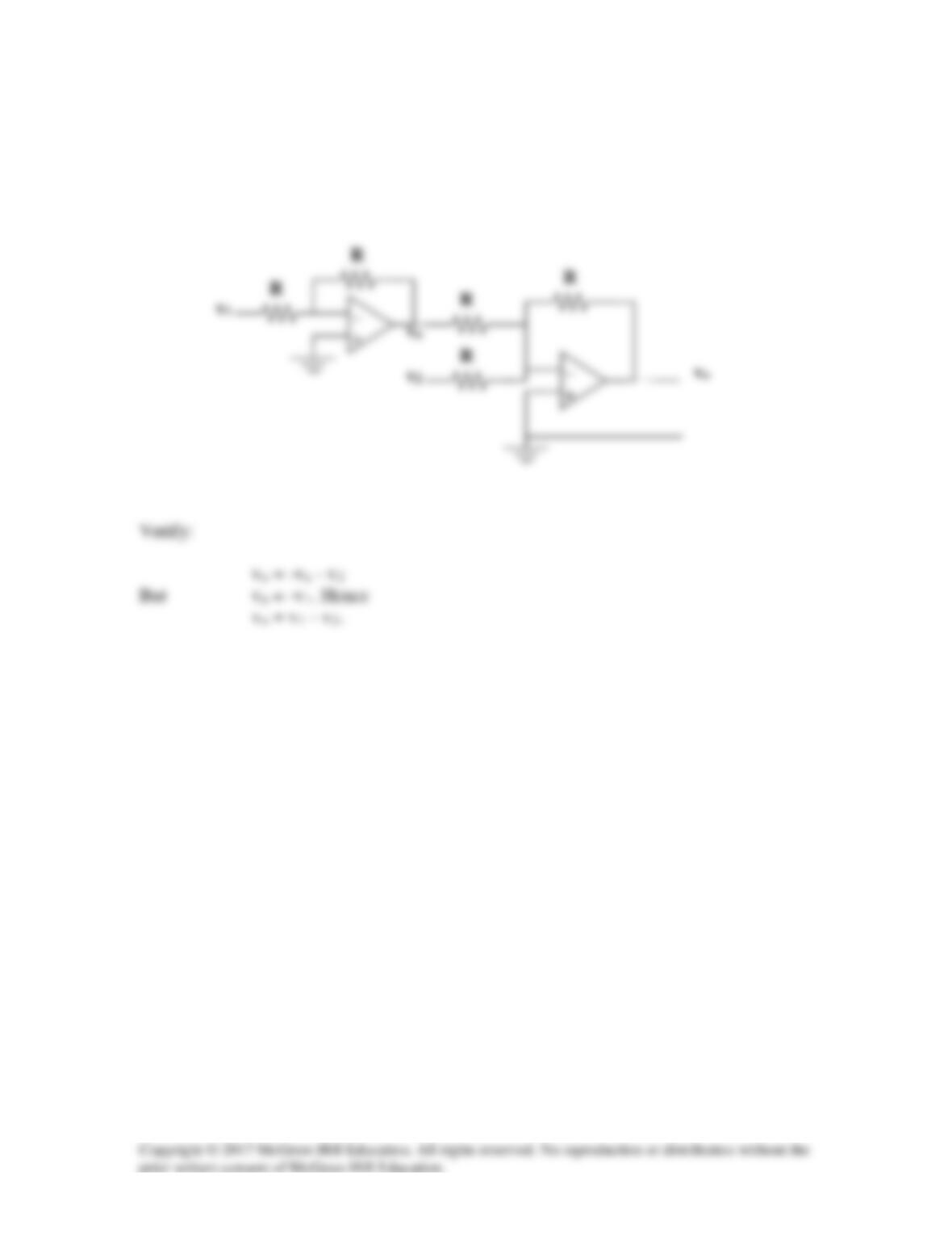
Using only two op amps, design a circuit to solve,
Solution
Although there are several ways to accomplish this, the easiest way is to simplify the
above equation and then design the circuit. Thus,
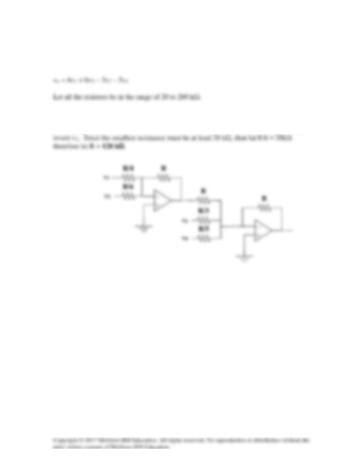
Solution 5.47
Using eq. (5.18),
12 3 4
2 , R 30 , R 2 , R 20Rk k k k=Ω=Ω=Ω=Ω
Solution 5.48
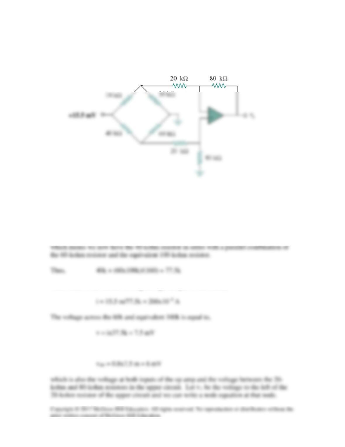
The circuit in Fig. 5.80 is a differential amplifier driven by a bridge. Find vo.
Figure 5.80
For Prob. 5.48.
Solution
We can break this problem up into parts. The 15.5 mV source separates the lower circuit
from the upper. In addition, there is no current flowing into the input of the op amp
which leads to the current flowing through this part of the circuit,
We can now calculate the voltage across the 80-kohm resistor.
The current through the 20k-ohm resistor, left to right, is,
Solution 5.49
R1 = R3 = 20kΩ, R2/(R1) = 4
Solution 5.50
(a) We use a difference amplifier, as shown below:
R2
v2
R1
(b) We may apply the idea in Prob. 5.35.
We need an inverter to invert v1 and a summer, as shown below. We may let
R = 100 kΩ.
v1
v2
R2
v1
R1
Solution 5.51
We achieve this by cascading an inverting amplifier and two-input inverting summer as
shown below:
Solution 5.52
Design an op amp circuit such that
Solution
A summing amplifier shown below will achieve the objective. An inverter is inserted to
Solution 5.53
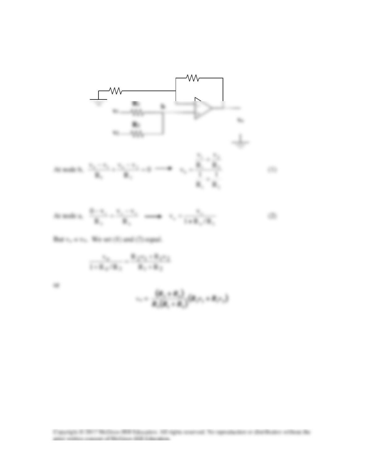
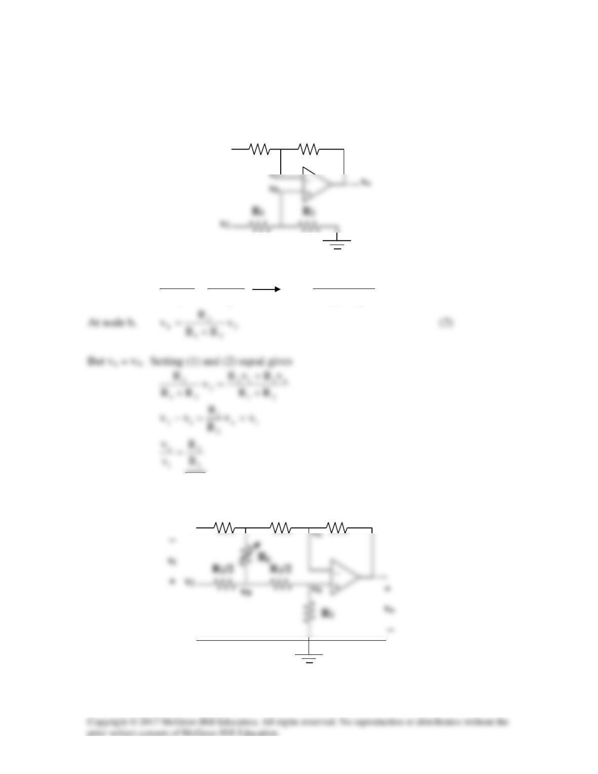
(a)
R2
v2
R1
vb
va
At node a,
2
oa
1
a1
R
vv
R
vv −
=
−
21
o112
aRR
vRvR
v+
+
=
(1)
(b)
v2
vB
va
vb
R2
v1
R1
R2
vA
v1
R1/2
R1/2
At node A,
2/R
vv
R
vv
2/R
vv
1
aA
g
AB
1
A1 −
=
−
+
−
At node B,
g
bB
1
AB
1
B2
R
vv
2/R
vv
2/R
vv −
+
−
=
−
Subtracting (1) from (2),
Since, va = vb,
But for the difference amplifier,
Equating (3) and (4),
i
o
1
1
v
v
R
⋅=
(c) At node a,
2/R
vv
R
vv
2
Aa
1
a1 −
=
−
Since va = vb, we subtract (1) from (2),
At node A,
vv
vv
vv oA
AB
Aa −
−
−
At node B,
0v
vv
vv B
AB
Bb −
=
−
−
−
Subtracting (5) from (4),
( )
oBAAB
2
AB
vvvvv
R
R
vv −−=−+−
g
Combining (3) and (6),
2
2
R
R−=
+
−
Solution 5.54
The first stage is a summer (please note that we let the output of the first stage be v1).
Solution 5.55
Let A1 = k, A2 = k, and A3 = k/(4)