Solution 2.57
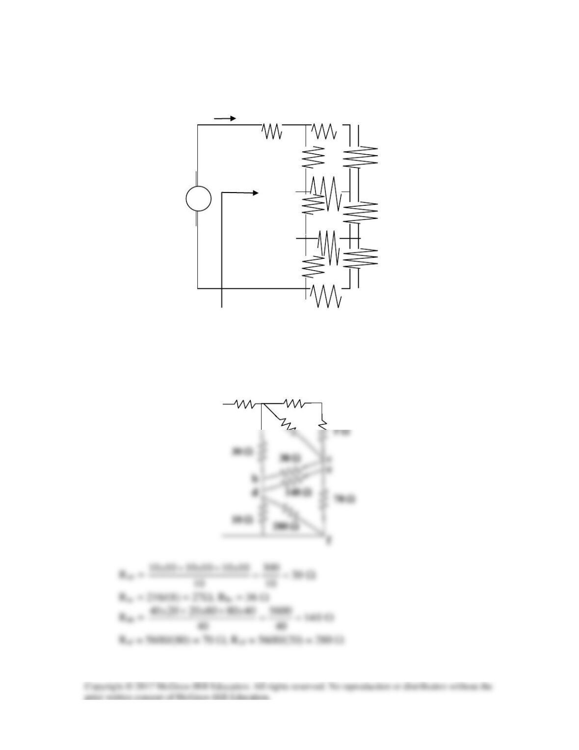
Find Req and I in the circuit of Fig. 2.121.
Figure 2.121
For Prob. 2.57.
Solution
10 Ω
280 Ω
5 Ω
30 Ω
70 Ω
140 Ω
30 Ω
d
c
10 Ω
25 Ω
30 Ω
a
50 V
+
−
10
Ω
10 Ω
Req
10 Ω
25 Ω
80 Ω
25
Ω
15 Ω
20
Ω
5 Ω
10
Ω
10 Ω
I
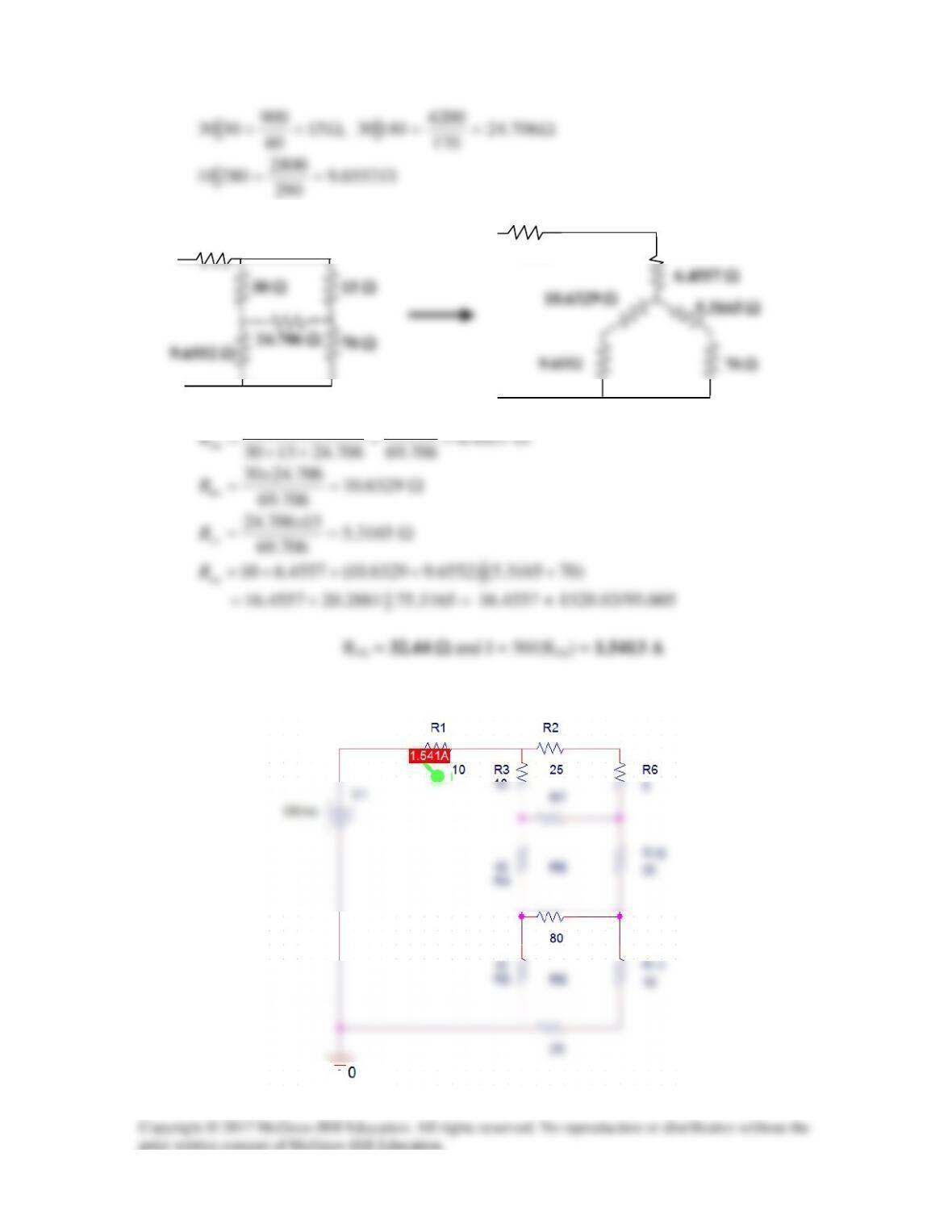
Combining resistors in parallel,
70 Ω
450
1530x
Checking with PSpice we get,
10 Ω
10 Ω
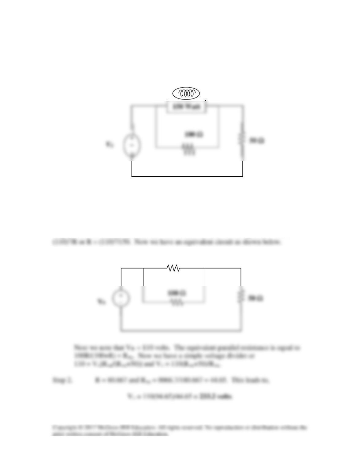
Solution 2.58
The 150 W light bulb in Fig. 2.122 is rated at 110 volts. Calculate the value of Vs to
make the light bulb operate at its rated conditions.
Figure 2.112
For Prob. 2.58.
Solution
Step 1. First we need to calculate the value of the resistance of the lightbulb. 150 =
R
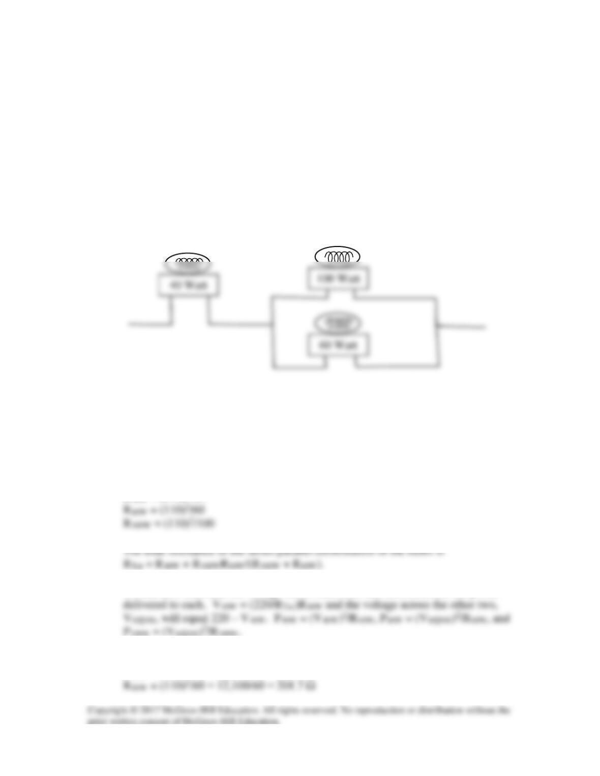
Solution 2.59
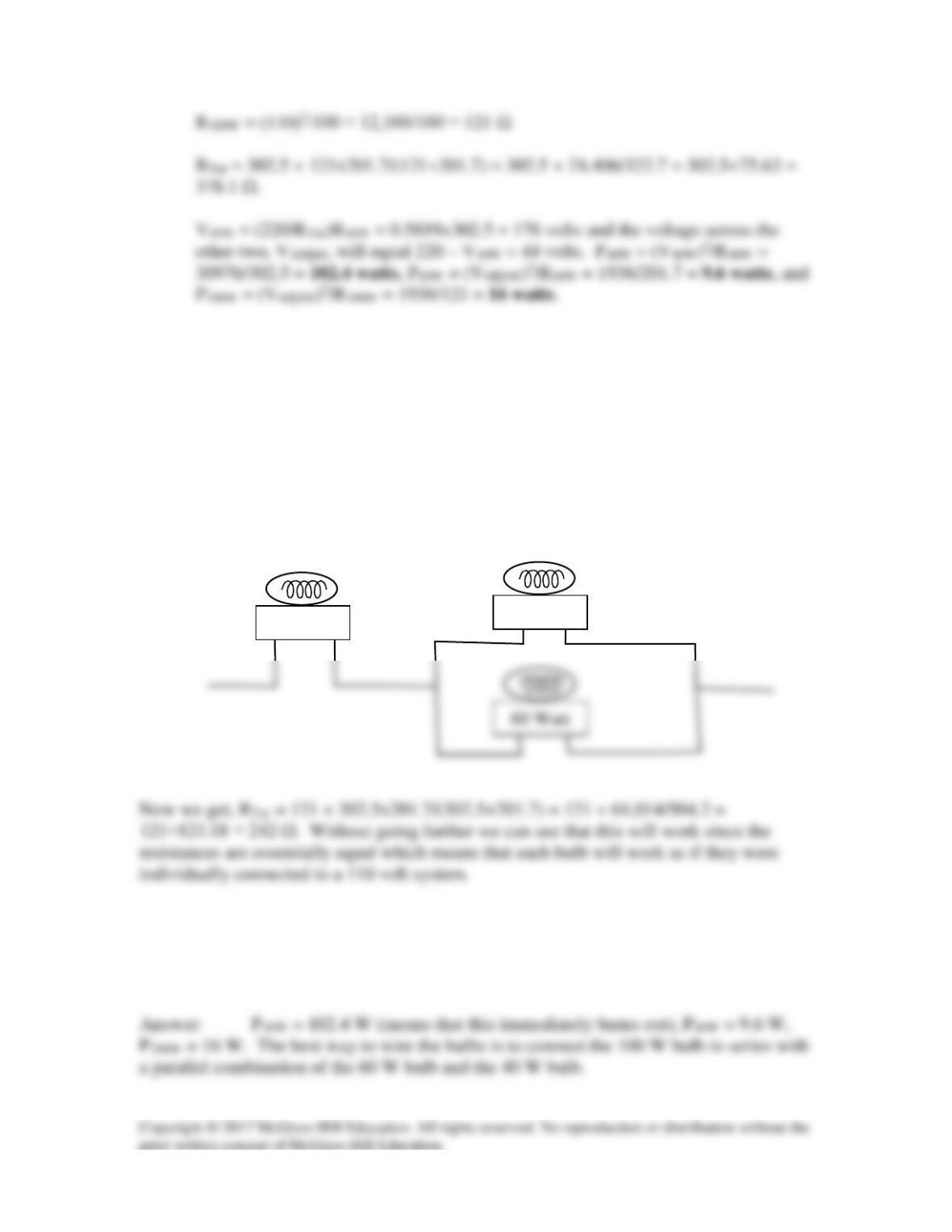
An enterprising young man travels to Europe carrying three lightbulbs he had purchased
in North America. The lightbulbs he has are a 100 watt lightbulb, a 60 watt lightbulb,
and a 40 watt lightbulb. Each lightbulb is rated at 110 volts. He wishes to connect these
to a 220 volt system that is found in Europe. For reasons we are not sure of, he connects
the 40 watt lightbulb in series with a parallel combination of the 60 watt lightbulb and the
100 watt lightbulb as shown Fig. 2.123. How much power is actually being delivered to
each lightbulb? What does he see when he first turns on the lightbulbs?
Is there a better way to connect these lightbulbs in order to have them work more
effectively?
Figure 2.123
For Prob. 2.59.
Solution
Step 1. Using p = v2/R, we can calculate the resistance of each bulb.
R40W = (110)2/40
We can now calculate the voltage across each bulb and then calculate the power
Step 2.
R40W = (110)2/40 = 12,100/40 = 302.5 Ω
Clearly when he flips the switch to light the bulbs the 40 watt bulb will flash bright as it
burns out! Not a good thing to do!
Is there a better way to connect them? There are two other possibilities. However what
if we place the bulb with the lowest resistance in series with a parallel combination of the
other two what happens? Logic would dictate that this might give the best result. So, let
us try the 100 watt bulb in series with the parallel combination of the other two as shown
below.
60 Watt
V100W = (220/RTot)121 = 110 and the voltage across the other two, V60||40, will equal 220
– V100W = 110. P100W = (V100W)2/121 = 100 watts, P60W = (V60||40)2/201.7 = 60 watts,
and P40W = (V60||40)2/302.5 = 40 watts. This will work!
100 Watt
40 Watt
Solution 2.60
Solution
Using p = v2/R, we can calculate the resistance of each bulb.
R30W = (120)2/30 = 14,400/30 = 480 Ω
Solution 2.61
There are three possibilities, but they must also satisfy the current range of 1.2 + 0.06 =
1.26 and 1.2 – 0.06 = 1.14.
(a) Use R1 and R2:
R =
Ω== 35.429080RR 21
(b) Use R1 and R3:
(c) Use R2 and R3:
R1 and R3
Solution 2.62
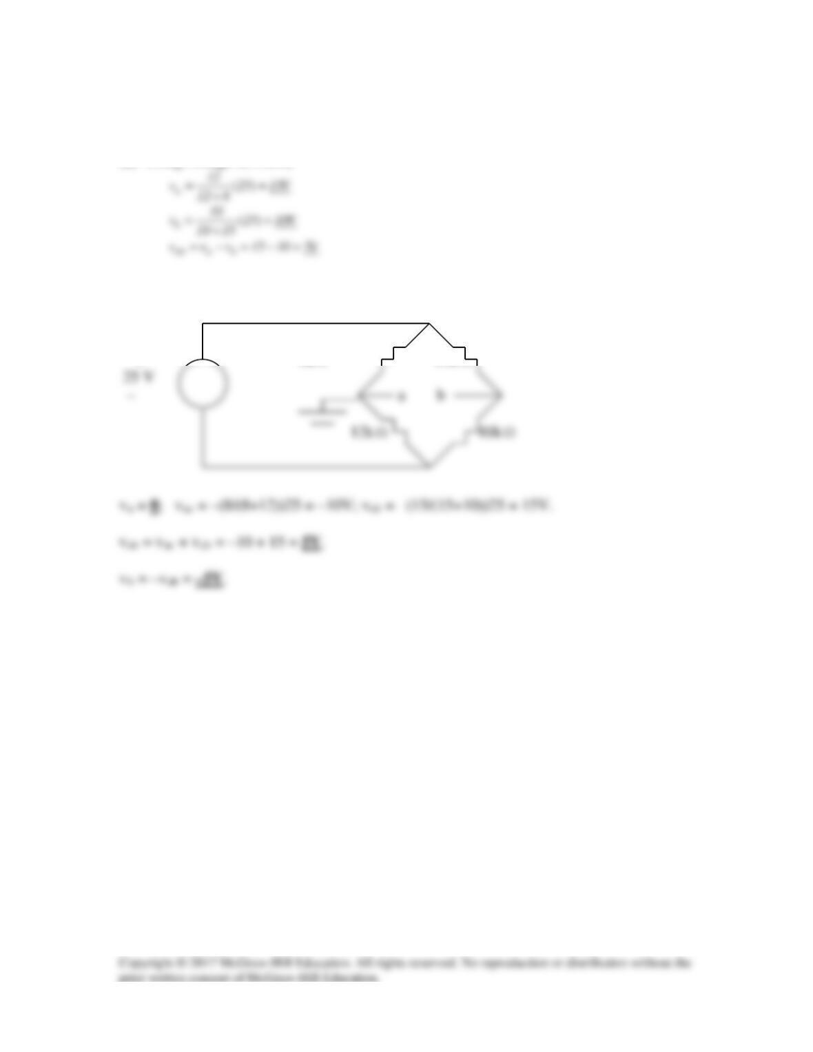
pA = 110×8 = 880 W, pB = 110×2 = 220 W
Solution 2.63
Use eq. (2.61),
−
100x10x2
I
3
m
Solution 2.64
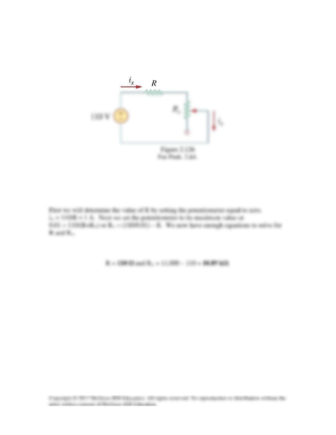
The potentiometer (adjustable resistor) Rx in Fig. 2.126 is to be designed to adjust
current Ix from 10 mA to 1 A. Calculate the values of R and Rx to achieve this.
Solution
Step 1. Even though there are an infinite number of combinations that can meet these
requirements, we will focus on making the potentiometer the most sensitive.
Step 2.
Solution 2.65
Design a circuit that uses a d’Arsonval meter (with an internal resistance of 2 kΩ that
Solution.
Step 1. Since 100 volts across the meter will cause the current through the meter to be
Solution 2.66
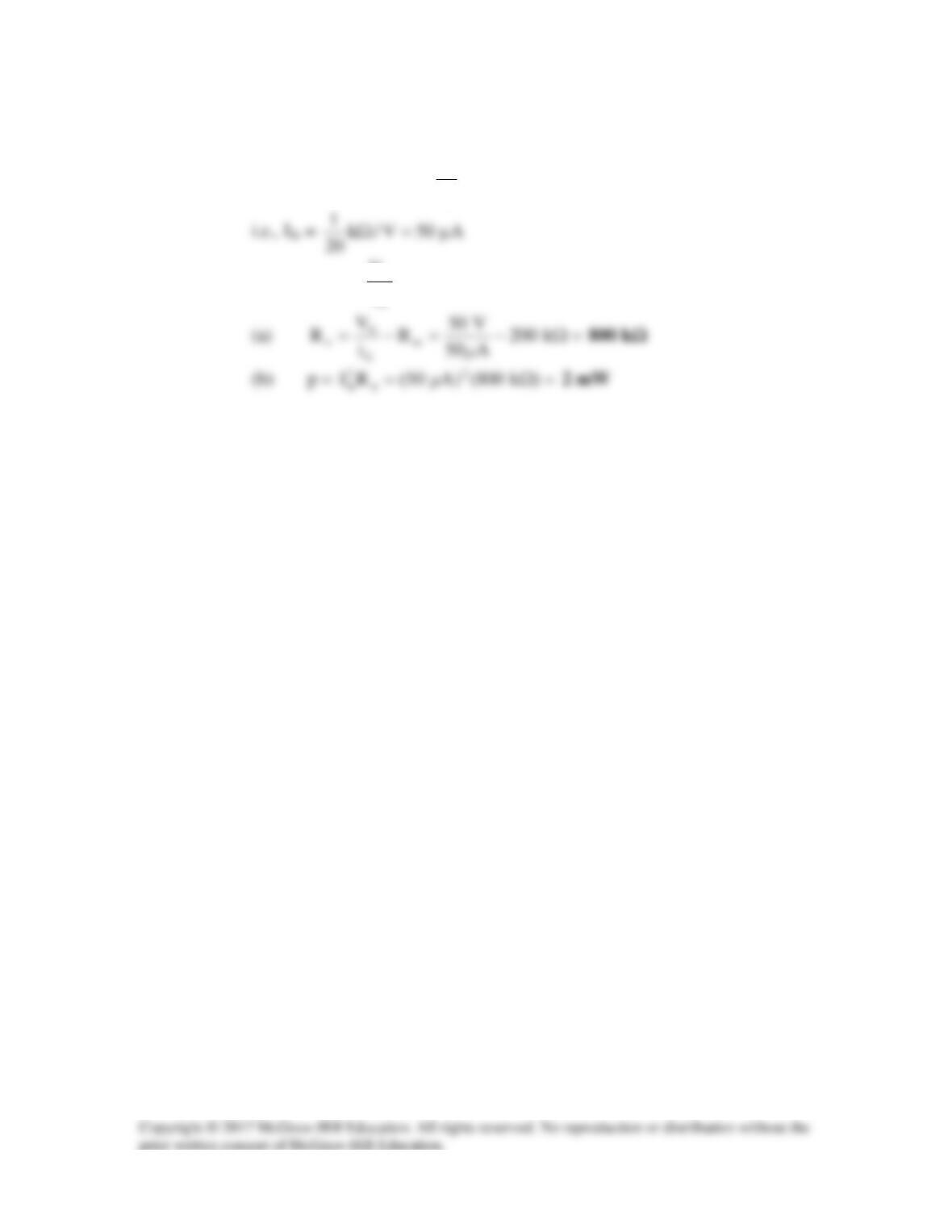
20 kΩ/V = sensitivity =
fs
I
1
The intended resistance Rm =
Ω=Ω= k200)V/k20(10
I
V
fs
Solution 2.67
(a) By current division,
(b)
.k4.2k6k4 Ω=
By current division,
(d)
.k6.3k36k4 Ω=Ω
By current division,
Solution 2.68
(a)
Ω= 602440
Solution 2.69
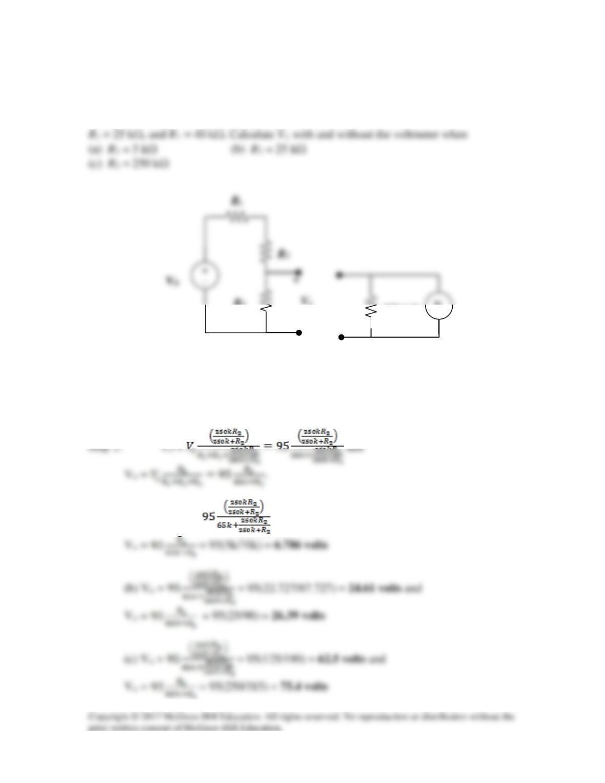
A voltmeter is used to measure Vo in the circuit in Fig. 2.129. The voltmeter model
consists of an ideal voltmeter in parallel with a 250-kΩ resistor. Let Vs = 95 V,
Figure 2.129
For Prob. 2.69
Solution
Step 2. (a) Vo = = 95(4.902/69.902) = 6.662 volts and
−
Vo
R2
250 kΩ
V
Solution 2.70
(a) Using voltage division,
(b) c
+ 8k
Ω
15k
Ω
Ω
Ω