Solution 7.75
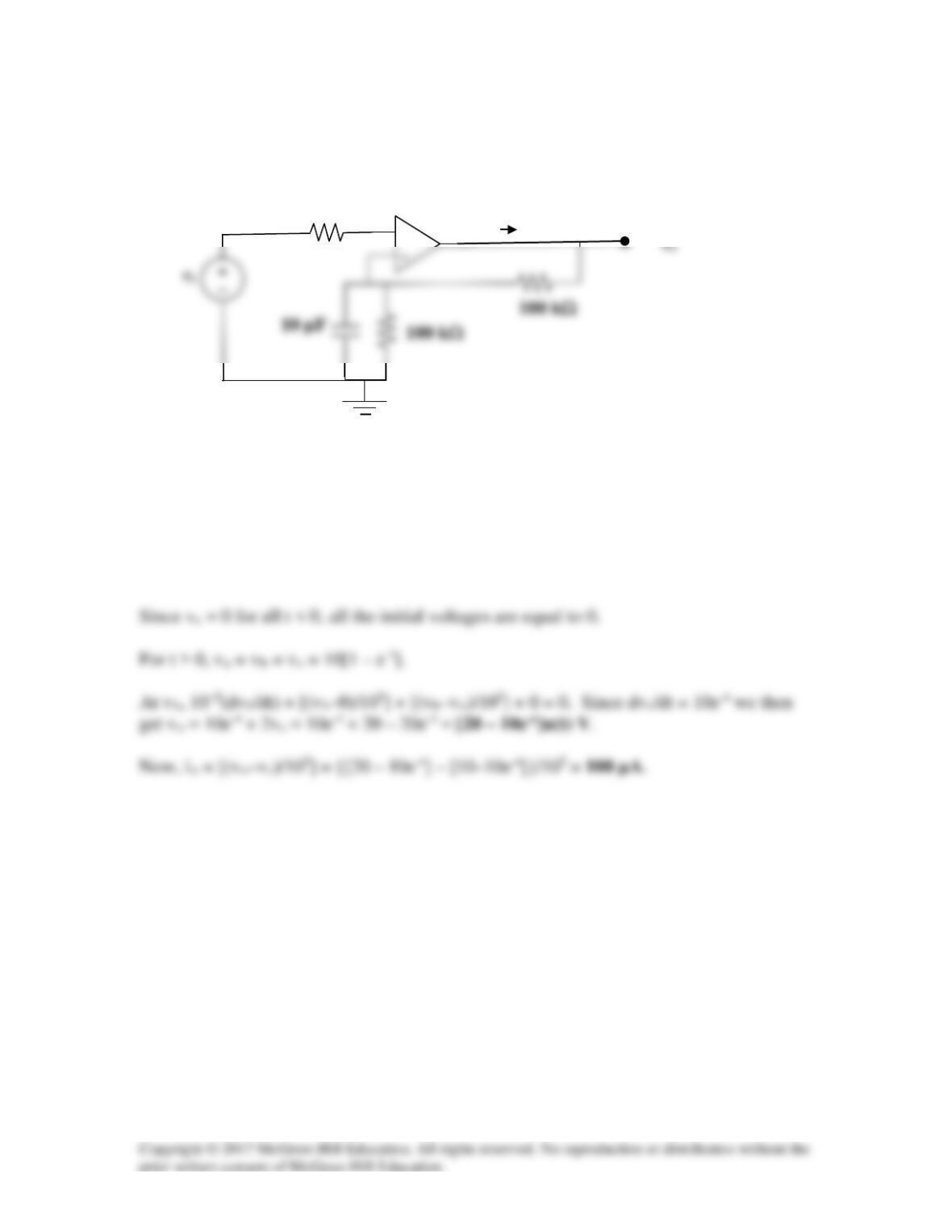
In the circuit of Fig. 7.140, find vo and io, given that vs = 10[1 – e–t]u(t) V.
Figure 7.140
For Prob. 7.75.
Solution
Let va = voltage at the noninverting terminal and let vb = voltage at the inverting
terminal.
+
10 Ω
io
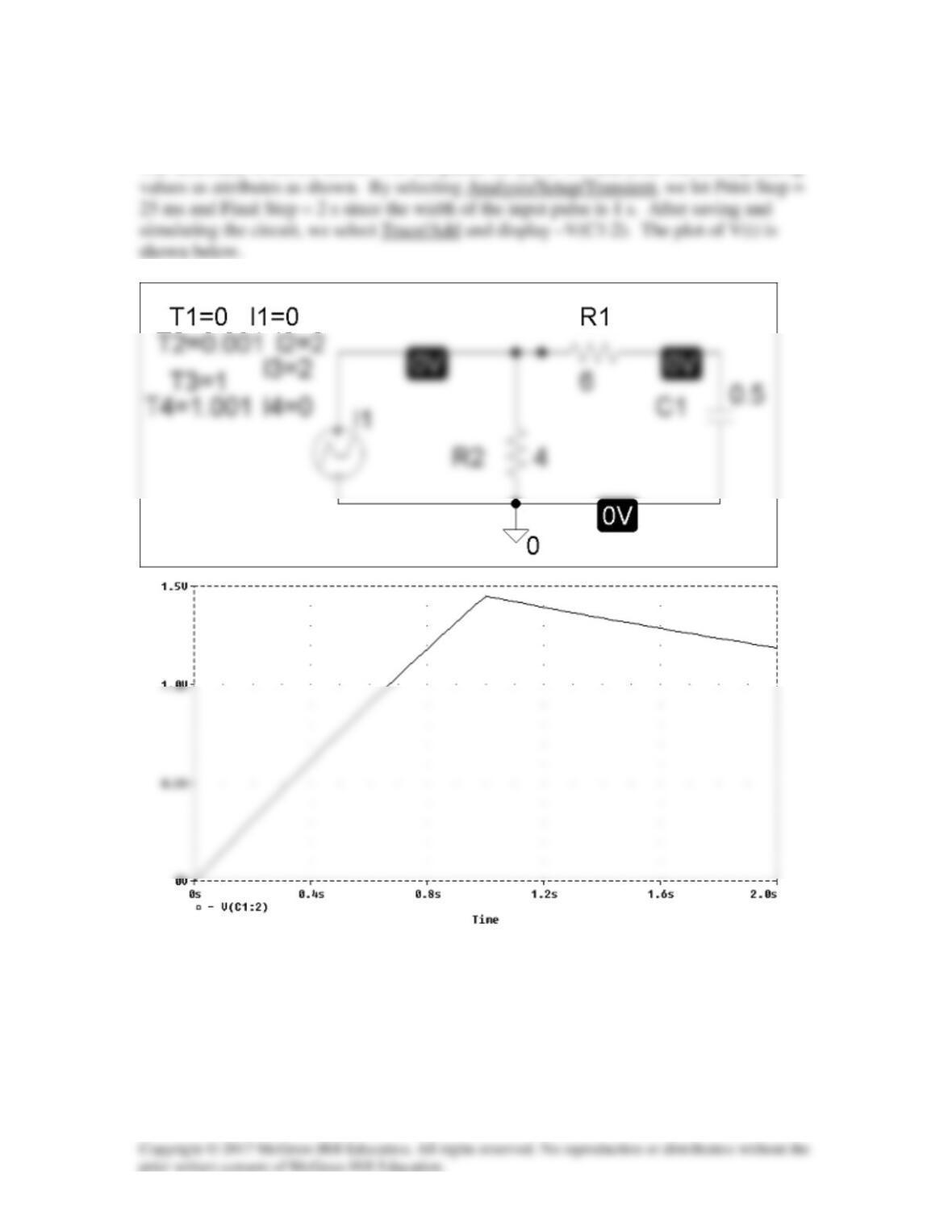
Solution 7.76
The schematic is shown below. For the pulse, we use IPWL and enter the corresponding
Solution 7.77
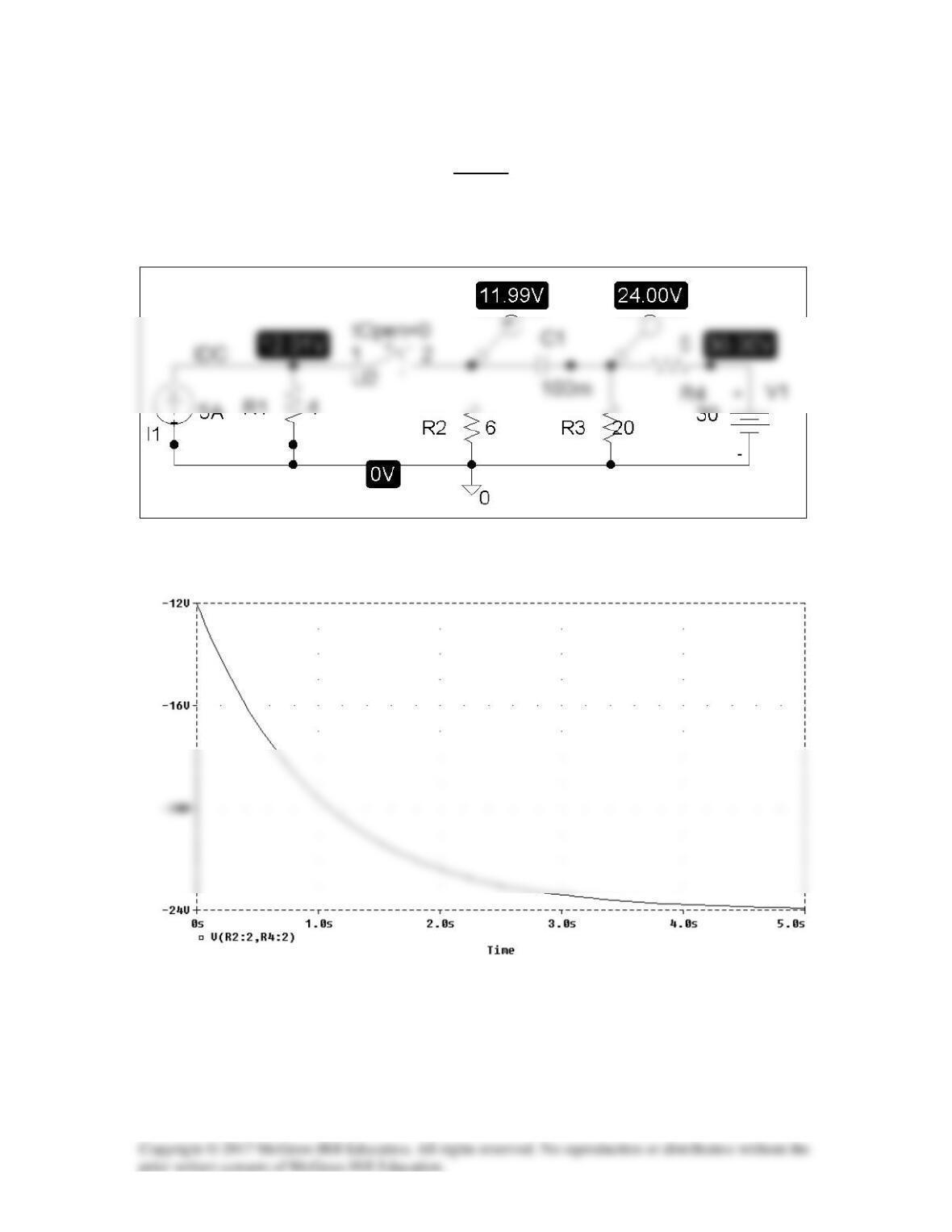
The schematic is shown below. We click Marker and insert Mark Voltage Differential at
the terminals of the capacitor to display V after simulation. The plot of V is shown
below. Note from the plot that V(0) = 12 V and V(∞) = -24 V which are correct.
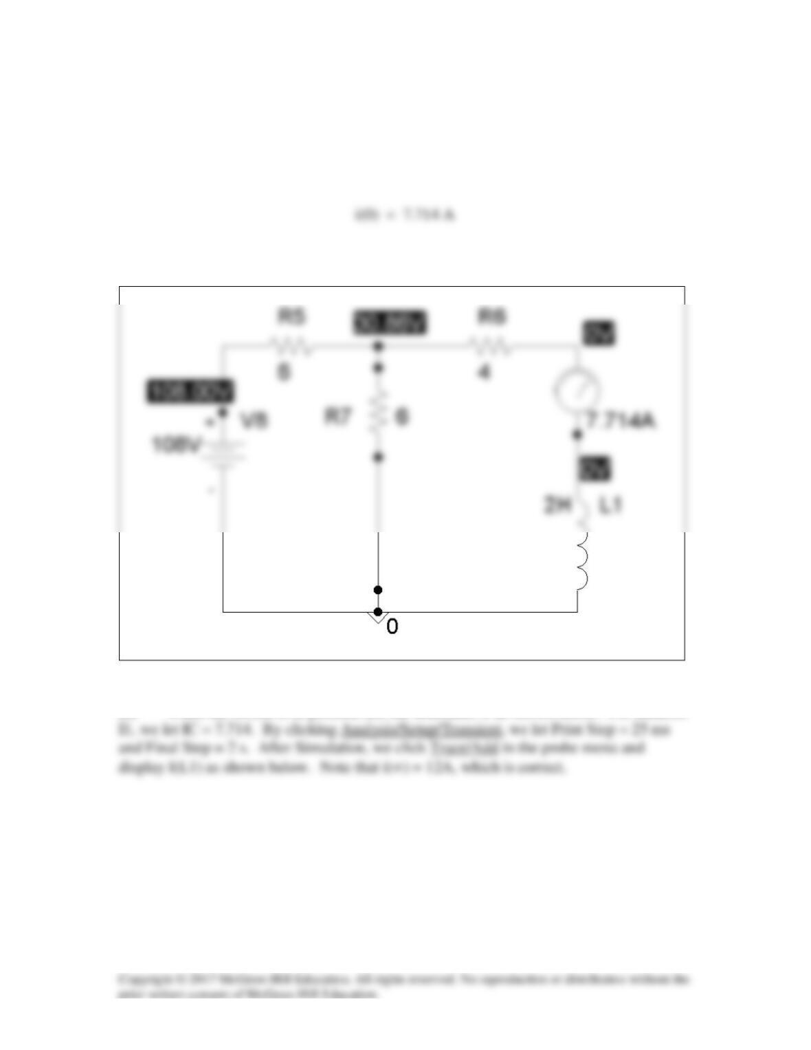
Solution 7.78
(a) When the switch is in position (a), the schematic is shown below. We insert
IPROBE to display i. After simulation, we obtain,
from the display of IPROBE.
(b) When the switch is in position (b), the schematic is as shown below. For inductor
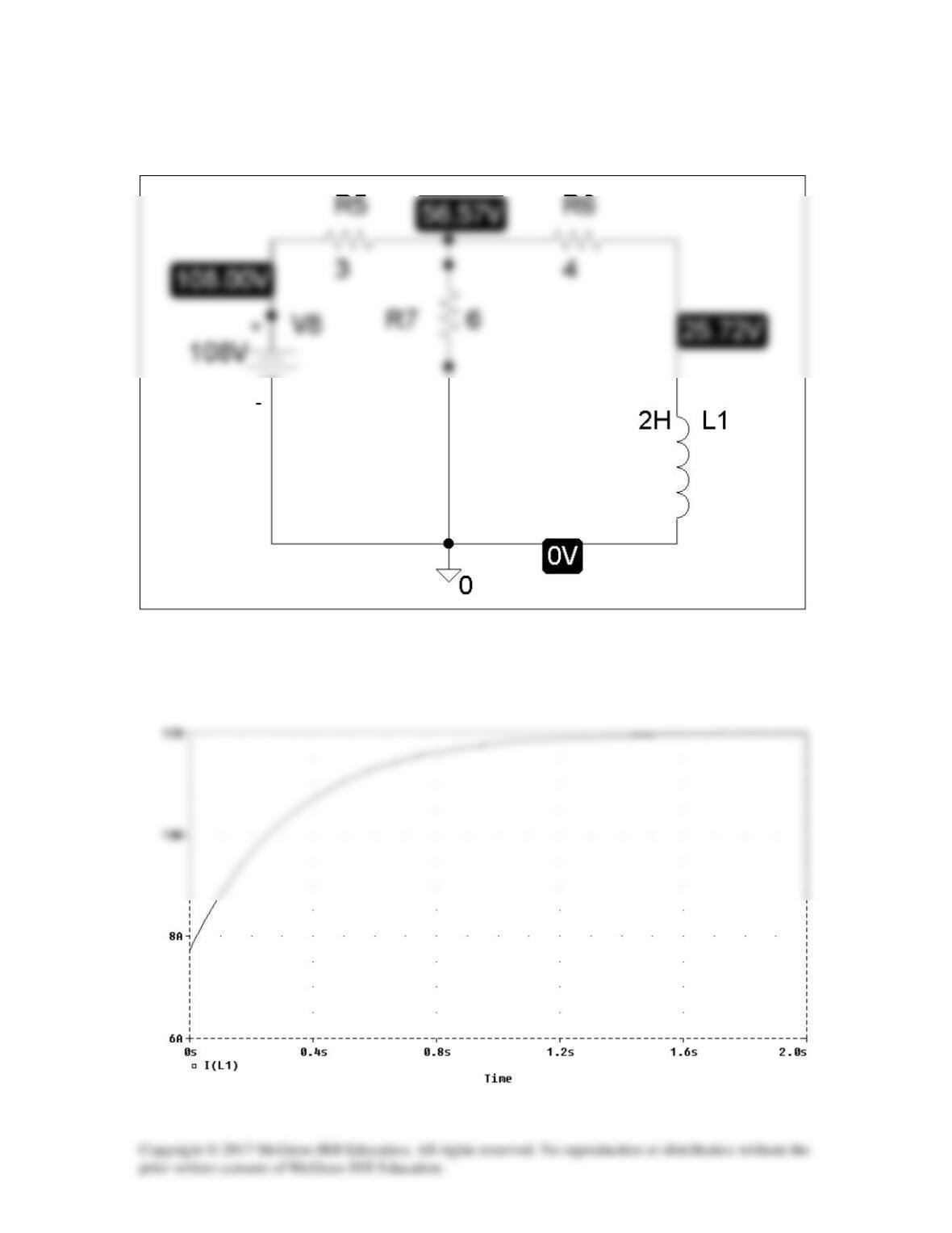
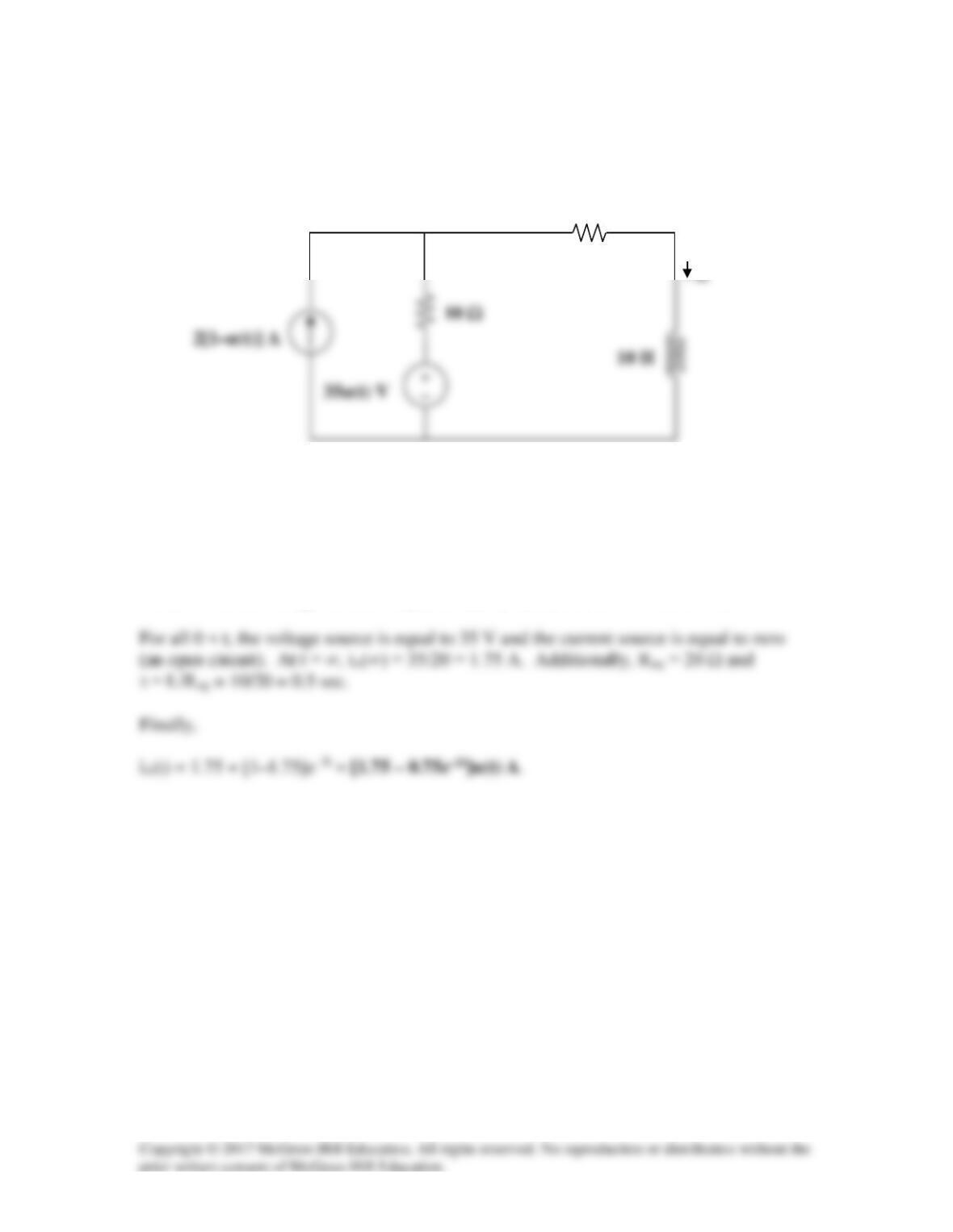
Solution 7.79
In the circuit in Fig. 7.143, determine io.
10 Ω
Figure 7.143
For Prob. 7.79.
Solution
For all t < 0, the voltage source is equal to zero (a short) and io = 2×10/(10+10) = 1 A.
10 Ω
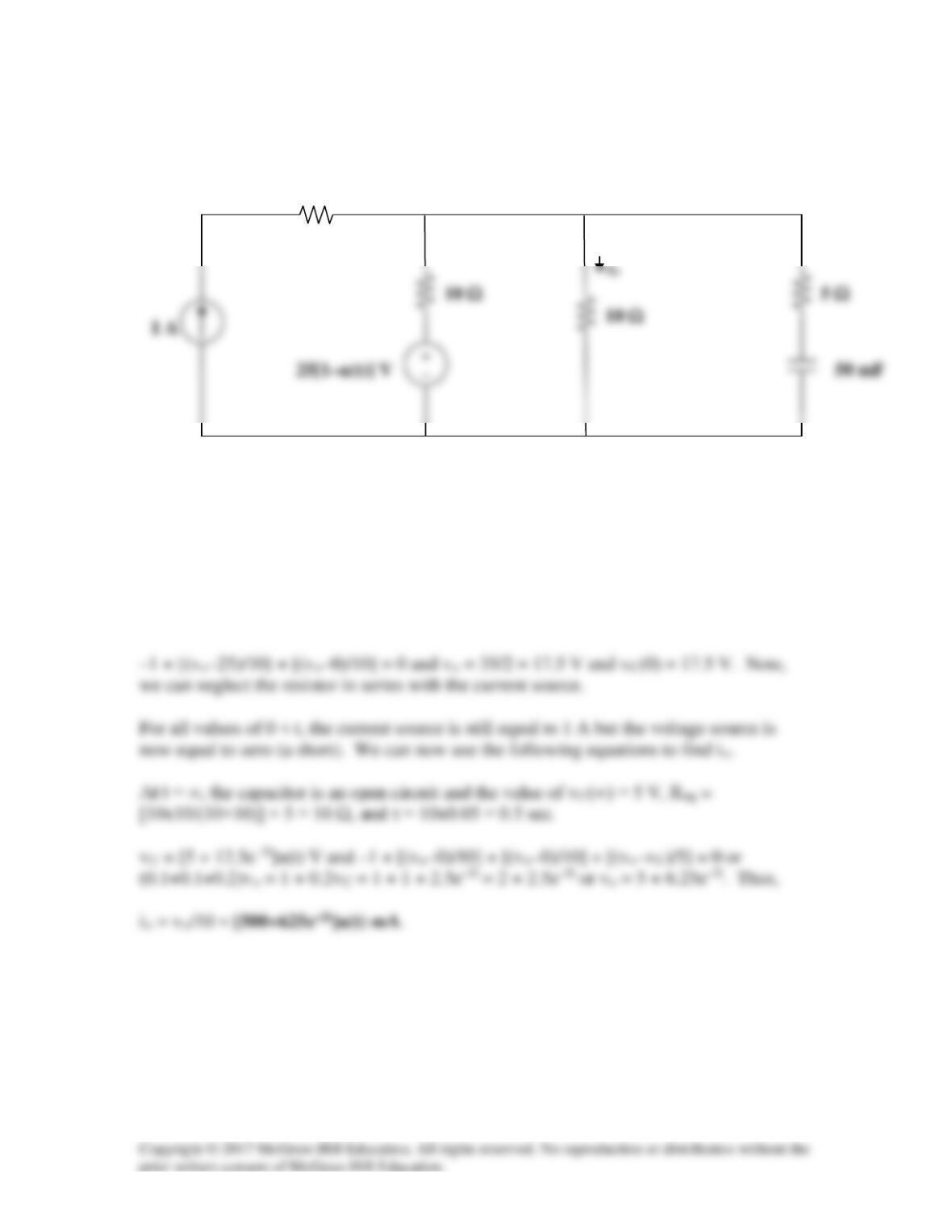
Solution 7.80
In the circuit of Fig. 7.144, find the value of io for all values of 0 < t.
10 Ω
10 Ω
Figure 7.144
For Prob. 7.80.
Solution
For all values of t < 0, the current source is equal to 1 A and the voltage source is equal to
25 V. In addition the capacitor is equal to an open circuit. Thus, if we let vo be the
voltage at the top node and taking the bottom node as reference we get,
10 Ω
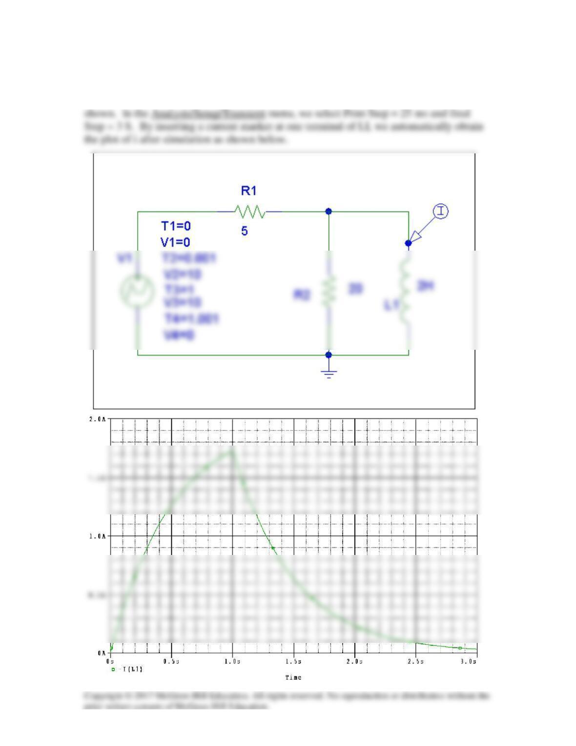
Solution 7.81
The schematic is shown below. We use VPWL for the pulse and specify the attributes as

Solution 7.82
Solution 7.83
sxxxRCvv 51010151034,0)0(,120)(
66
=====∞
−
τ

Solution 7.84
A capacitor with a value of 10 mF has a leakage resistance of 2 MΩ. How long does it
take the voltage across the capacitor to decay to 40% of the initial voltage to which the
capacitor is charged? Assume that the capacitor is charged and then set aside by itself.
Solution
The voltage across a charged capacitor is equal to vC(t) = vC(0)e–t/τ where τ = RleakC =
Solution 7.85
(a) The light is on from 75 volts until 30 volts. During that time we essentially have
a 120-ohm resistor in parallel with a 6–µF capacitor.
(b)
s24)106)(104(RC
-66
=××==τ
Dividing (1) by (2),
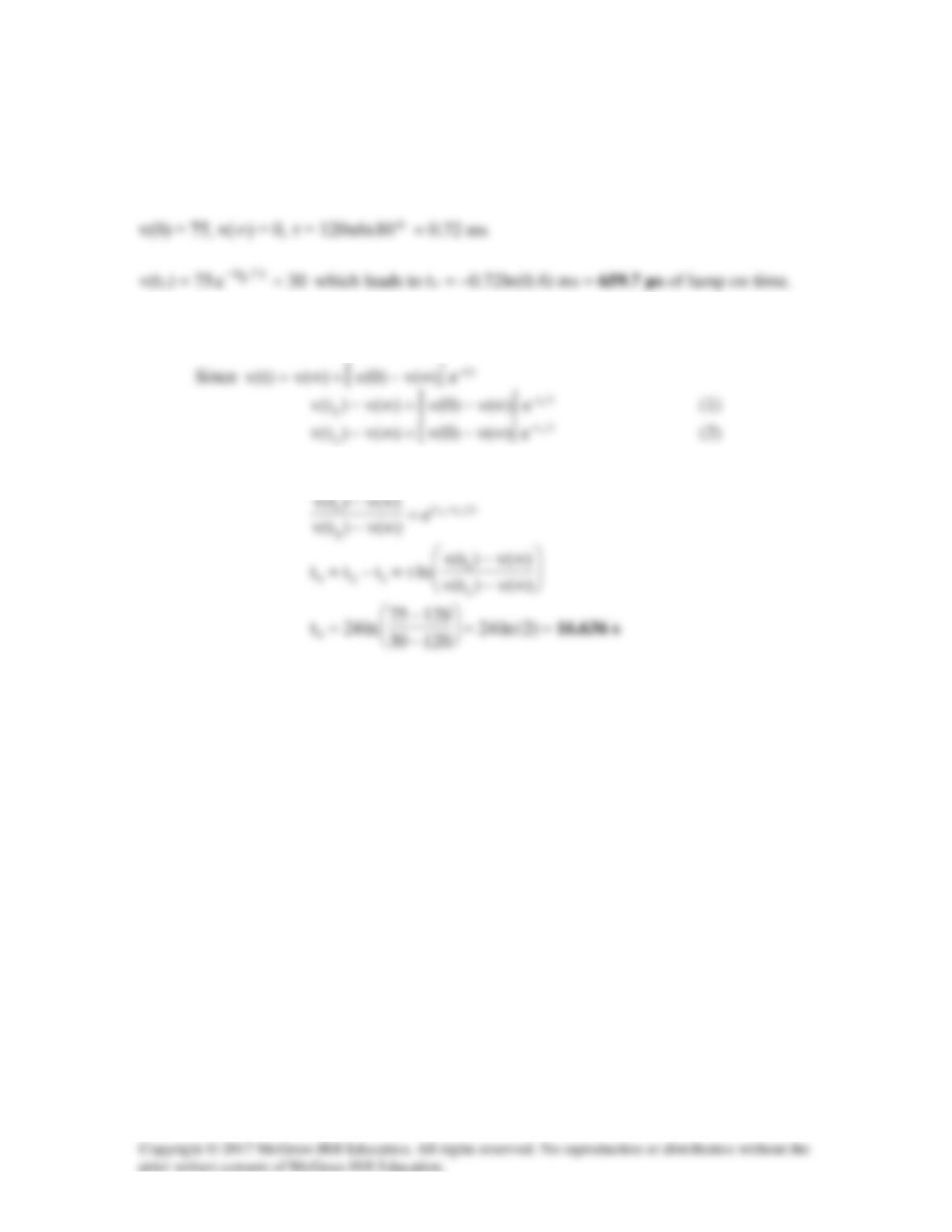
Solution 7.86
[ ]
τ
∞−+∞=
t–
e)(v)0(v)(v)t(v
12)(v =∞
,
0)0(v =
For
Ω= k100R
,
For
Ω= M1R
,
Thus,
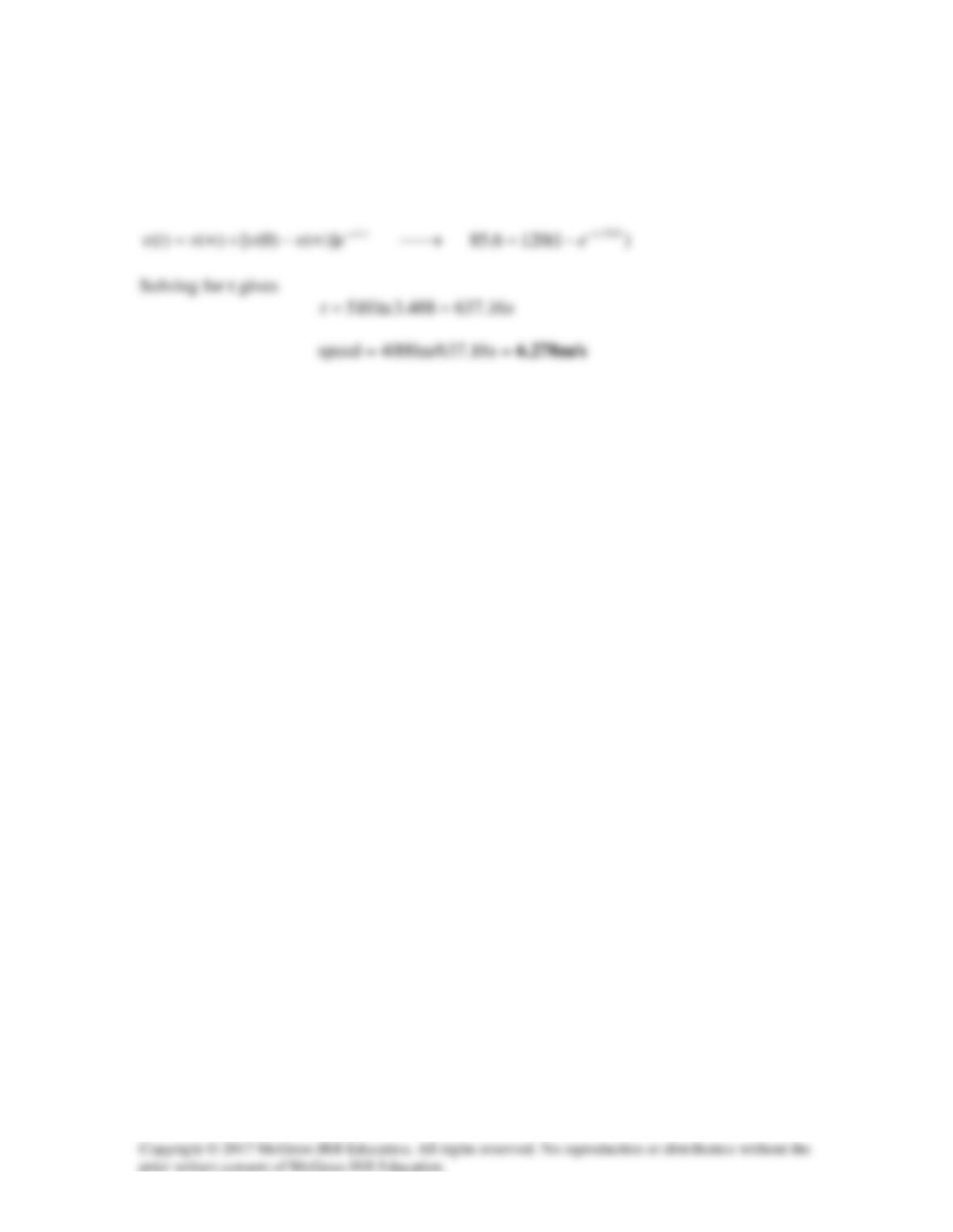
Solution 7.87
Let i be the inductor current.
For t > 0, we have an RL circuit
At t = 100 ms = 0.1 s,
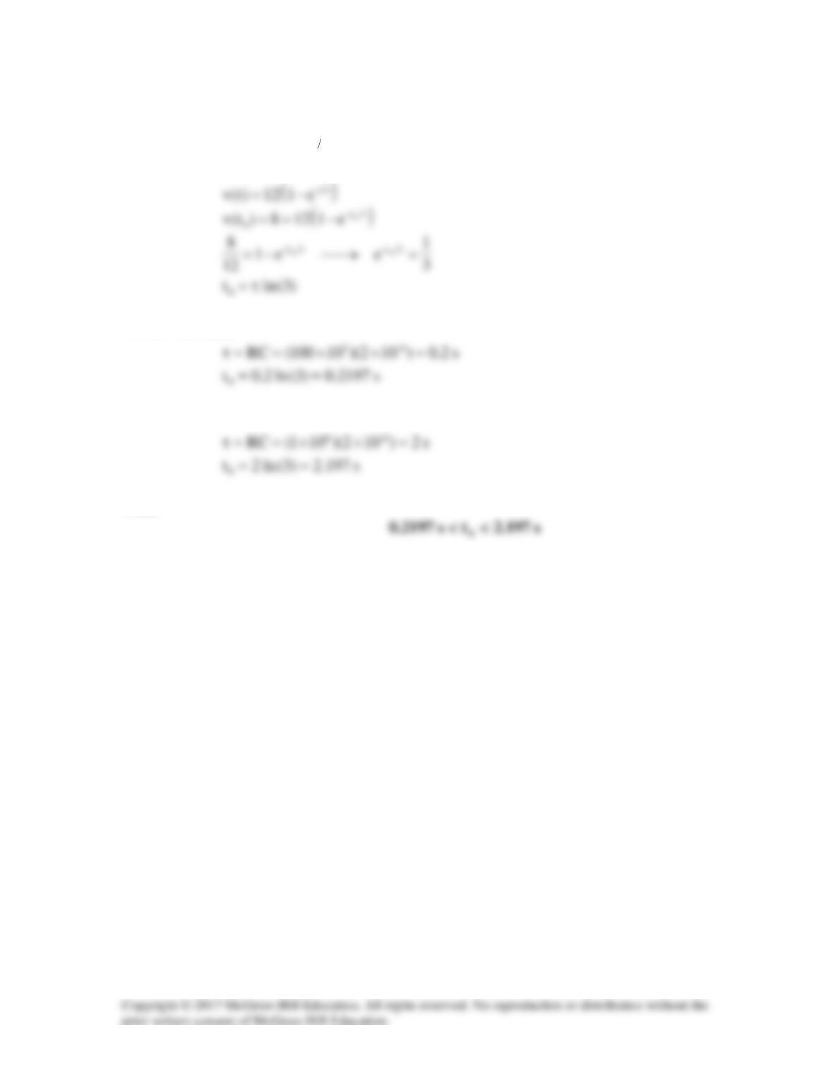
Solution 7.88
(a)
s60)10200)(10300(RC
-123
µ=××==τ

Solution 7.89
Since
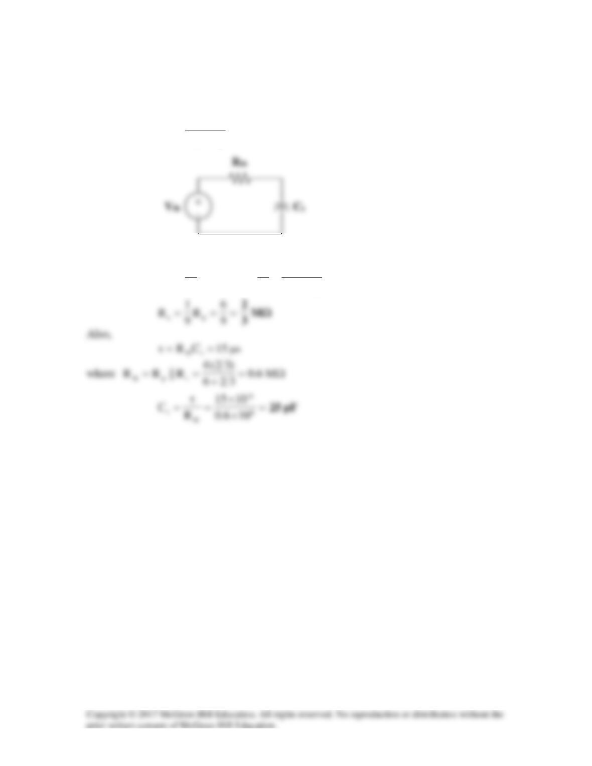
s1T1.0 µ=<τ
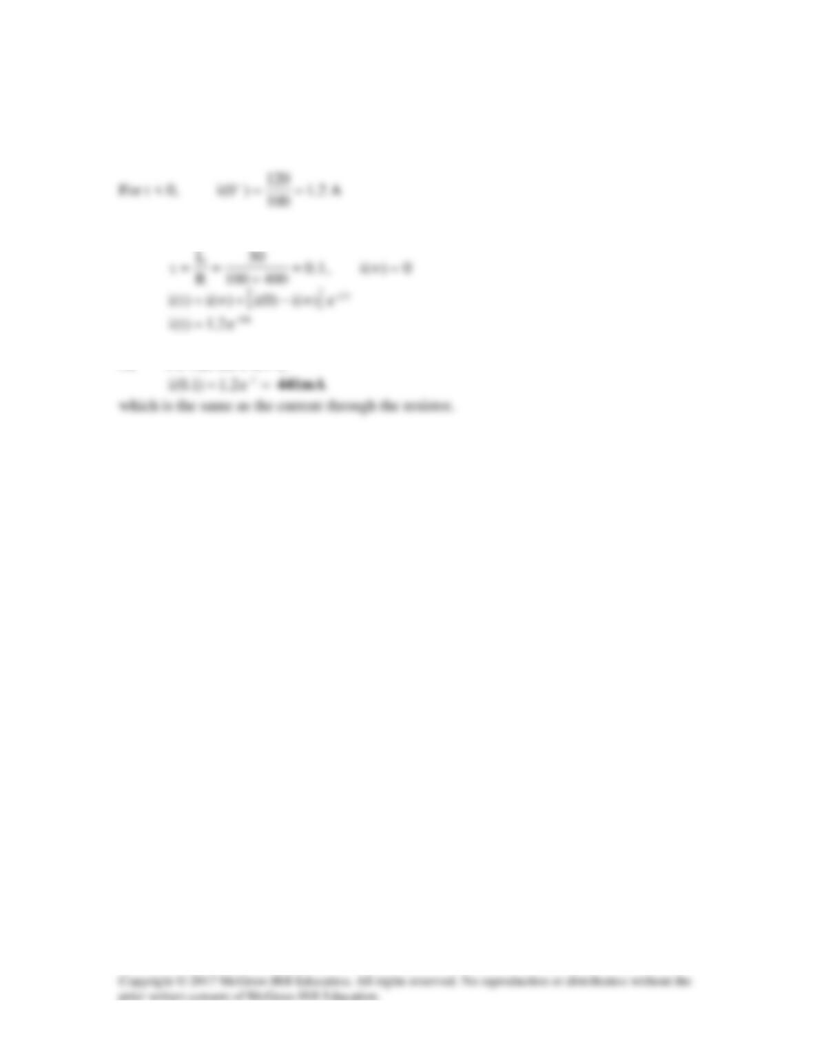
Solution 7.90
We determine the Thevenin equivalent circuit for the capacitor
s
C
.
i
ps
s
th v
RR
R
v+
=
,
psth R||RR =
The Thevenin equivalent is an RC circuit. Since
ps
s
ith RR
R
10
1
v
10
1
v+
=→=
Solution 7.91
mA240
12
)0(io==
,
0)(i =∞
2
L==τ
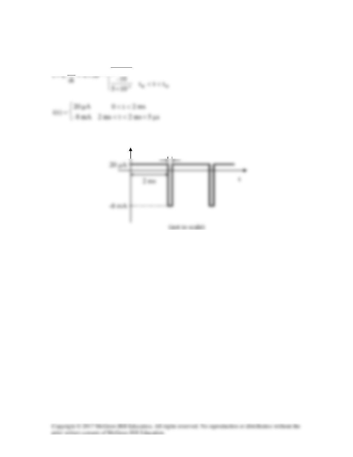
Solution 7.92
<<
×
R
3–
9–
tt0
102
10
dv
which is sketched below.
20 µA
i(t)
5 µs