Solution 13.29
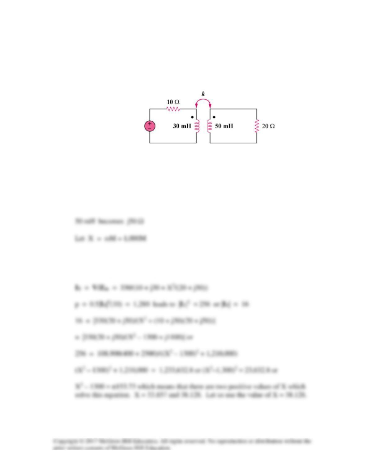
In the circuit of Fig. 13.97, find the value of the coupling coefficient k that will make the
10-Ω resistor dissipate 1.28 kW. For this value of k, find the energy stored in the coupled
coils at t = 1.5 s.
Figure 13.97
For Prob. 13.29.
Solution
30 mH becomes jωL = j30x10-3x103 = j30 Ω
Using the concept of reflected impedance,
Zin = 10 + j30 + X2/(20 + j50)
330 cos(1,000t) V
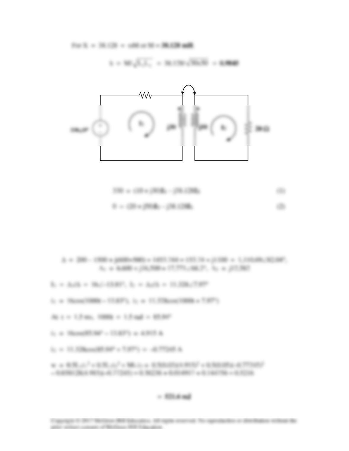
In matrix form,
+−
−+
=
2
1
I
I
50j20128.38j
128.38j30j10
0
330
j38.128 Ω
10 Ω
Solution 13.30
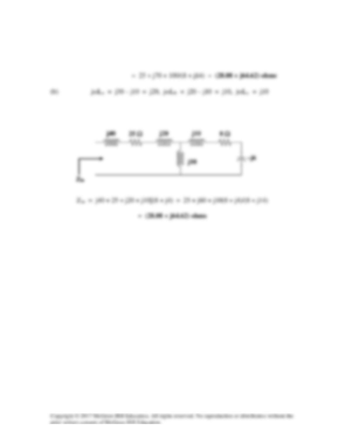
(a) Zin = j40 + 25 + j30 + (10)2/(8 + j20 – j6)
Thus the Thevenin Equivalent of the linear transformer is shown below.
Solution 13.31
Using Fig. 13.100, design a problem to help other students to better understand linear
transformers and how to find T-equivalent and Π–equivalent circuits.
Although there are many ways to solve this problem, this is an example based on the
same kind of problem asked in the third edition.
Problem
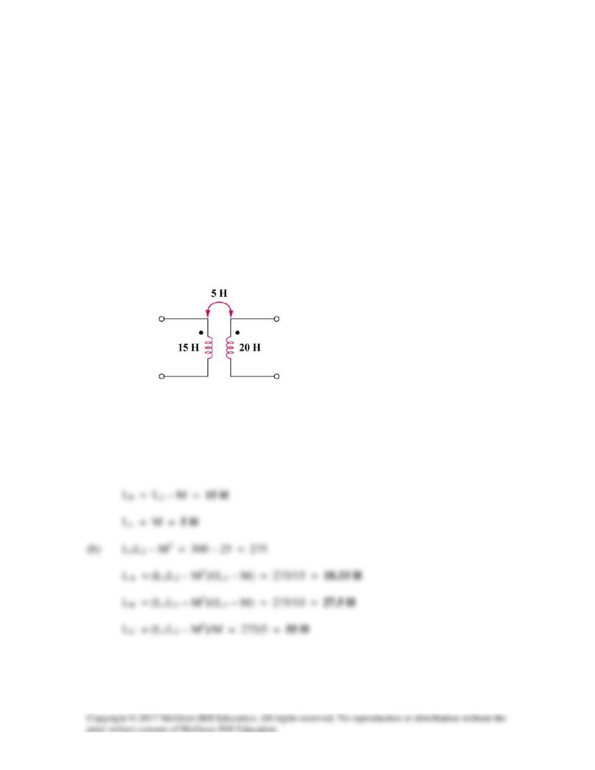
For the circuit in Fig. 13.99, find:
(a) the T–equivalent circuit,
(b) the Π-equivalent circuit.
Figure 13.99
Solution
(a) La = L1 – M = 10 H
Solution 13.32
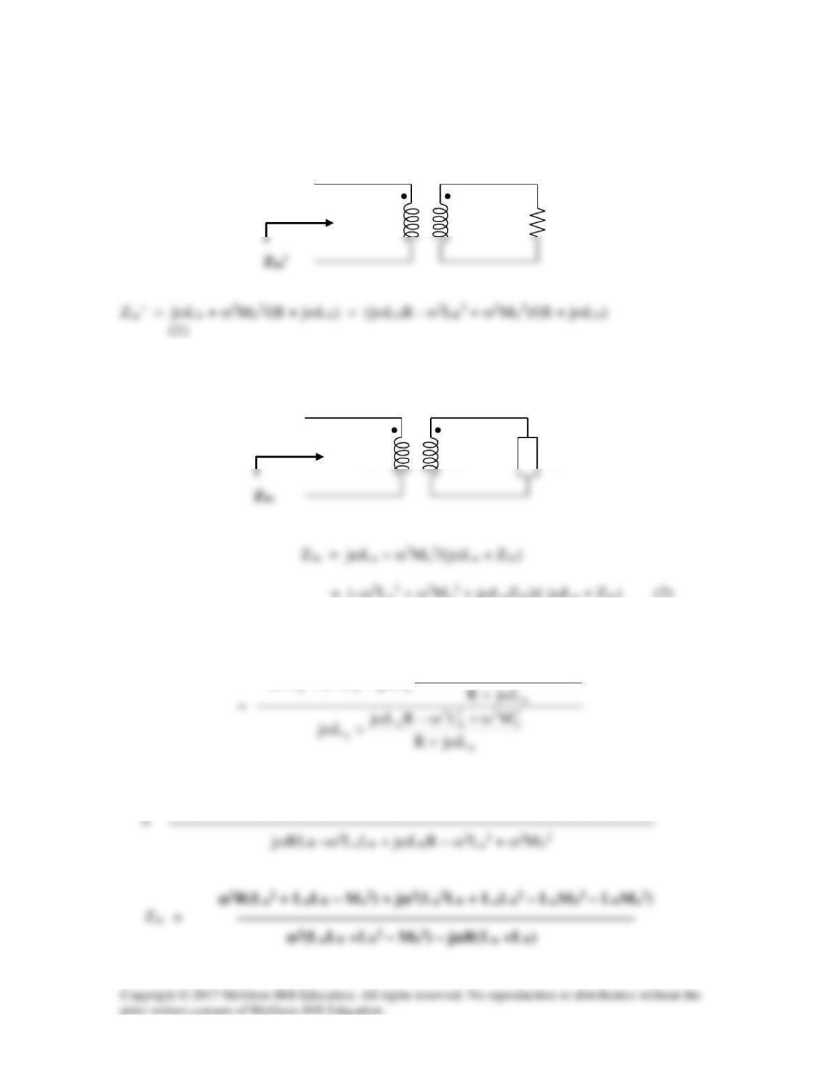
We first find Zin for the second stage using the concept of reflected impedance.
For the first stage, we have the circuit below.
= (–ω2La2 + ω2Ma2 + jωLaZin)/( jωLa + Zin) (2)
Substituting (1) into (2) gives,
2
b
22
b
2
b
2
22
2
)MLRLj(
LjML
ω+ω−ω
ω+ω+ω−
–Rω2La2 + ω2Ma2R – jω3LbLa + jω3LbMa2 + jωLa(jωLbR – ω2Lb2 + ω2Mb2)
R
Lb
LB
La
LA
Zin’


Solution 13.33
Solution 13.34
Using Fig. 13.103, design a problem to help other students to better understand how to
find the input impedance of circuits with transformers.
Although there are many ways to solve this problem, this is an example based on the
same kind of problem asked in the third edition.
Problem
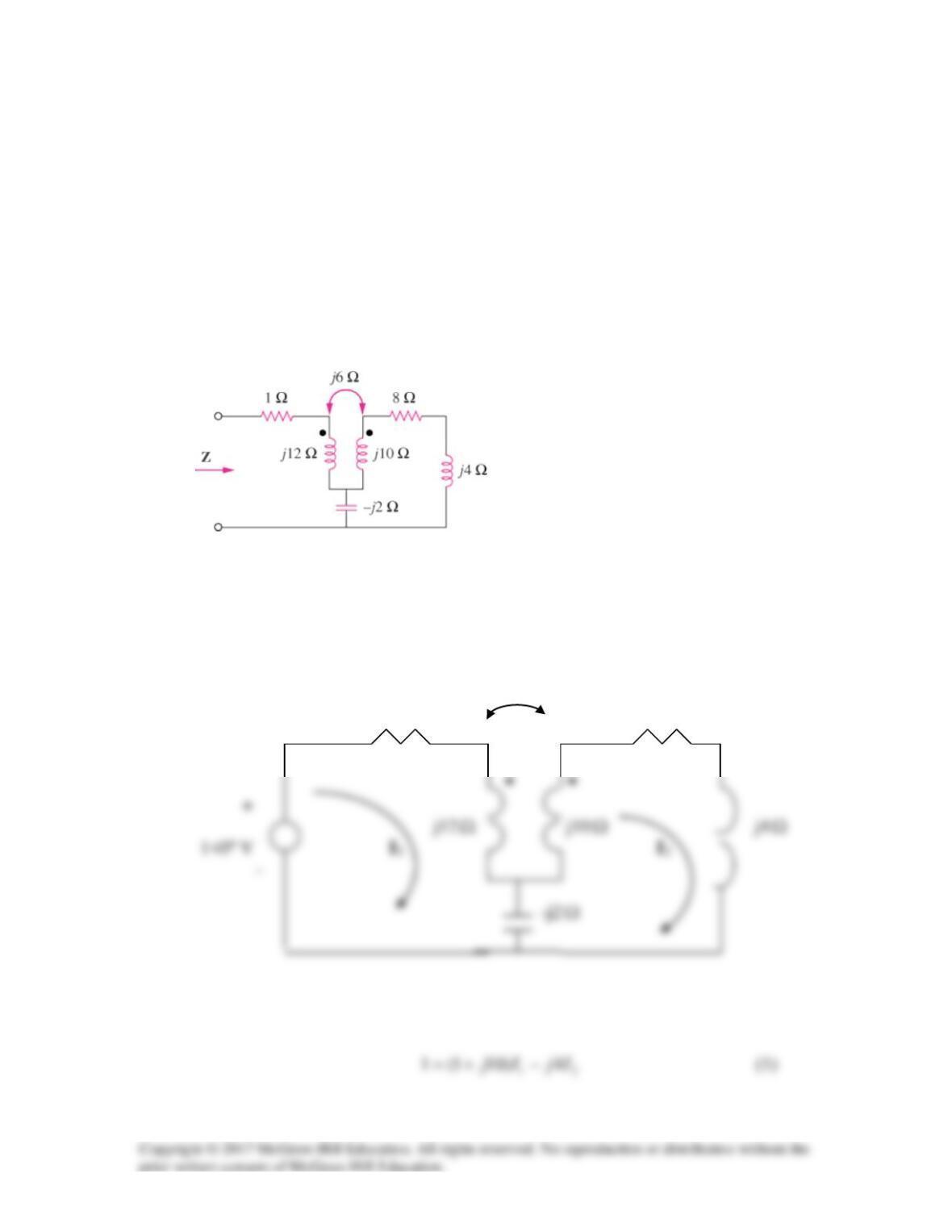
Find the input impedance of the circuit in Fig. 13.102.
Figure 13.102
Solution
Insert a 1-V voltage source at the input as shown below.
j6
Ω
1
Ω
8
Ω
For loop 1,
For loop 2,
Solving (1) and (2) leads to I1=0.019 –j0.1068
Solution 13.35
For mesh 1,
We may use MATLAB to solve (1) to (3) and obtain
Solution 13.36
Following the two rules in section 13.5, we obtain the following:
(a) V2/V1 = –n, I2/I1 = –1/n (n = V2/V1)
Solution 13.37
A 240/2400 V (rms) step-up ideal transformer delivers 50 kW to a resistive load.
Calculate: (a) the turns ratio, (b) the primary current, (c) the secondary current.
Solution
Solution 13.38
Design a problem to help other students to better understand ideal transformers.
Although there are many ways to solve this problem, this is an example based on the
same kind of problem asked in the third edition.
Problem
A 4-kVA, 2300/230-V rms transformer has an equivalent impedance of 2∠10°Ω on the
primary side. If the transformer is connected to a load with 0.6 power factor leading,
calculate the input impedance.
Solution
Zin = Zp + ZL/n2, n = v2/v1 = 230/2300 = 0.1

Solution 13.39
Referred to the high-voltage side,
ZL = (1200/240)2(0.8∠10°) = 20∠10°
Solution 13.40
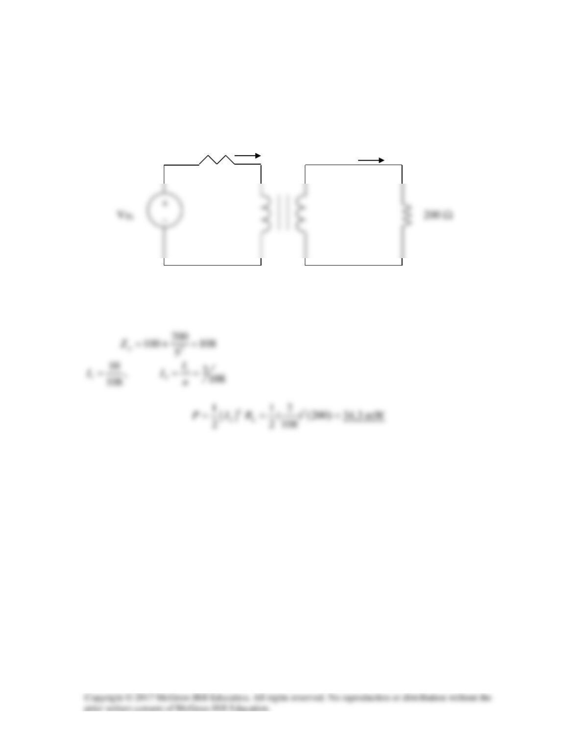
Consider the circuit as shown below.
V
We reflect the 200–Ω load to the primary side.
1:5
I
1
I
2
R
Th
Solution 13.41
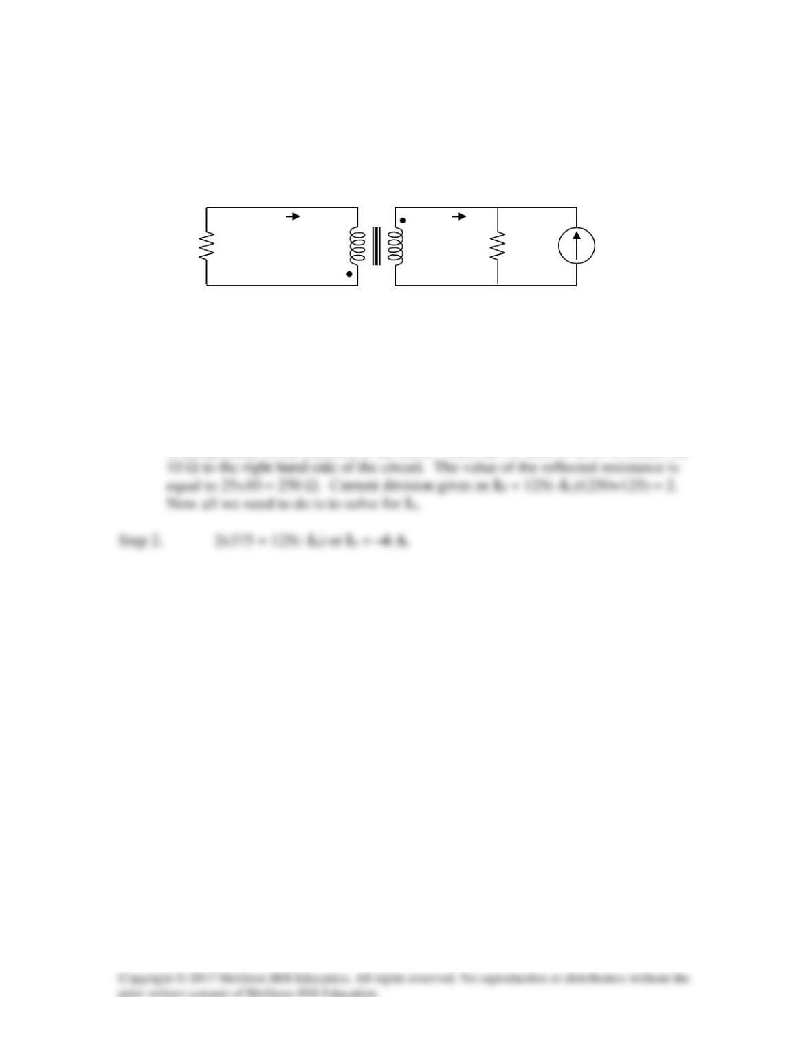
Given I2 = 2 A, determine the value of Is.
Figure 13.105
For Prob. 13.41.
Solution
Step 1. First we note that the dots are not relevant for this problem (the value of I2
is independent of the location of the dots). Thus, all we need to do is to reflect the
I1
1 : 5
I2
125 Ω
Is
10 Ω
Solution 13.42
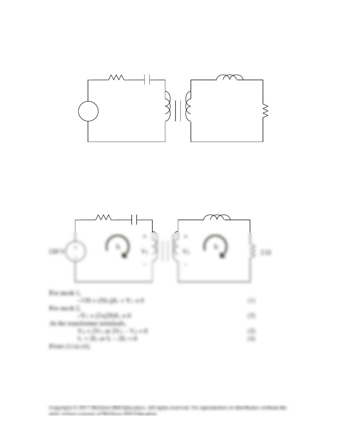
For the circuit in Fig. 13.106, determine the power absorbed by the 2 Ω resistor. Assume
the 120 V source is an rms value.
Figure 13.106
For Prob. 13.42.
Solution
We apply mesh analysis to the circuit as shown below.
+
2 Ω
_
_
50 Ω
j20 Ω
–j1 Ω
1:2
50 Ω
+
_
2 Ω
•
•
j20
–j1 Ω
120∠ 0° V
Ideal
1:2
1
I
50 j 0 1 0 120
−
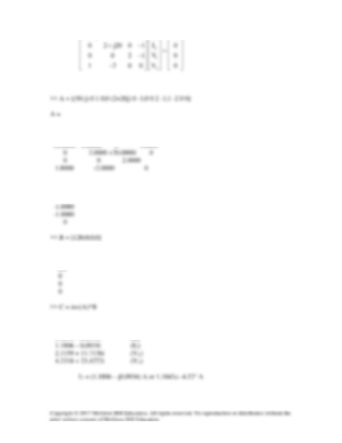
Solving this with MATLAB,
Columns 1 through 3
Column 4
0
B =
C =
The power absorbed by the 2-Ω resistor is

Solution 13.43
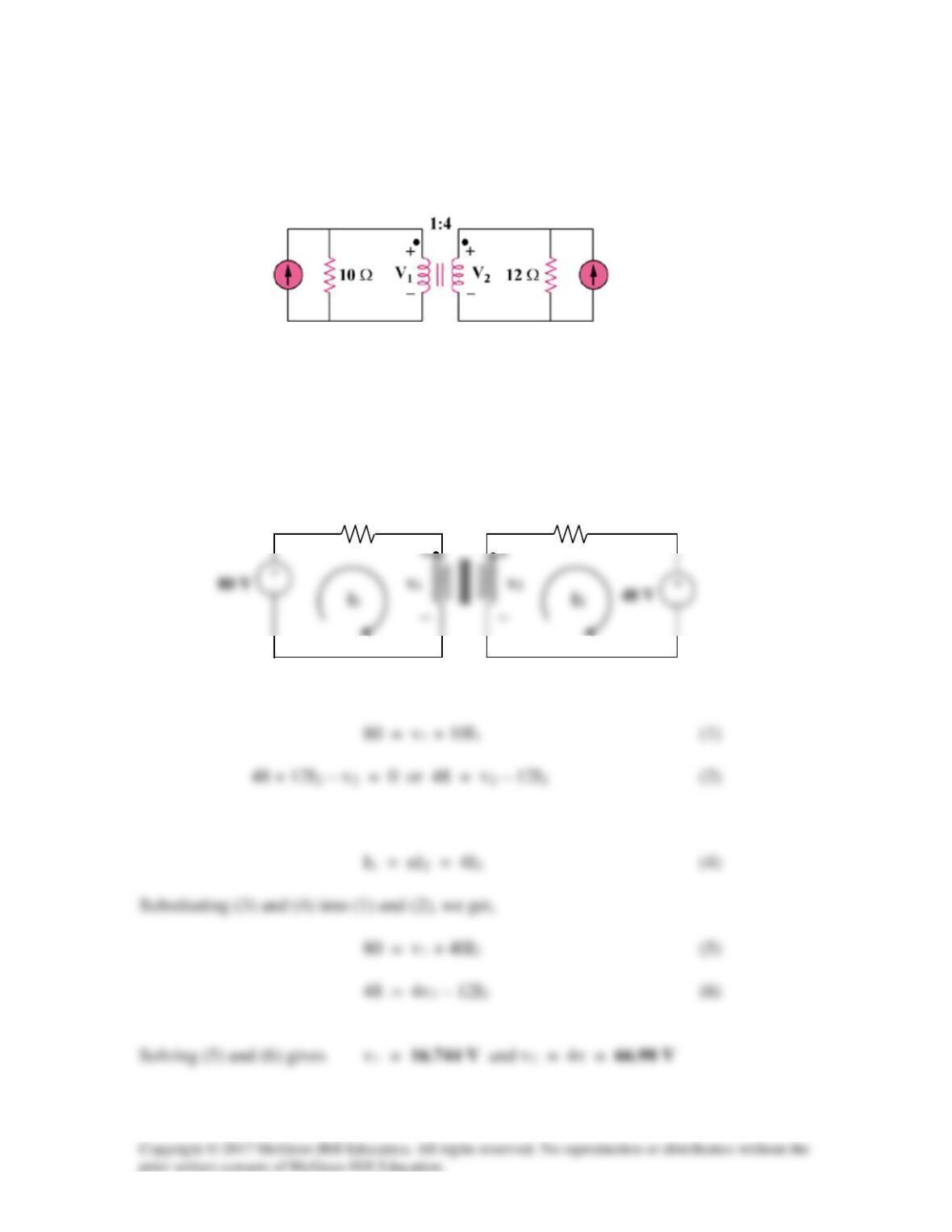
Obtain V1 and V2 in the ideal transformer circuit of Fig. 13.107.
Figure 13.107
For Prob. 13.43.
Solution
Transform the two current sources to voltage sources, as shown below.
Using mesh analysis, –80 + 10I1 + v1 = 0
At the transformer terminal, v2 = nv1 = 4v1 (3)
12 Ω
10 Ω
1 : 4
8∠0° A
4∠0° A