Archives
978-0073398167 Chapter 10 Solution Manual Part 1
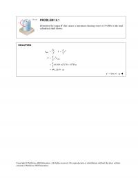
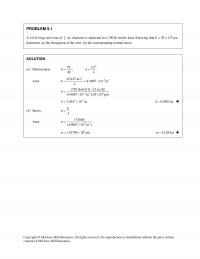
consent of McGraw–Hill Education. PROBLEM 10.1 Determine the torque T that causes a maximum shearing stress of 70 MPa in the steel cylindrical shaft shown. SOLUTION 4 max 3max 36 ;2 2 (0.018 m) (70 10 Pa) 2 641.26 N […]
978-0073398167 Chapter 10 Solution Manual Part 2
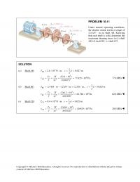
consent of McGraw–Hill Education. PROBLEM 10.11 Under normal operating conditions, the electric motor exerts a torque of 2.4 kN ⋅ m on shaft AB. Knowing that each shaft is solid, determine the maximum shearing stress in (a) shaft AB, (b) […]
978-0073398167 Chapter 10 Solution Manual Part 3
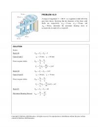
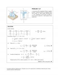
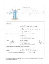
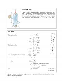
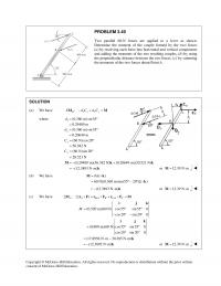
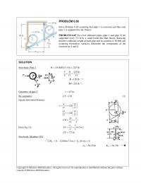
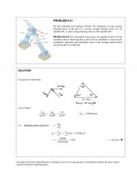
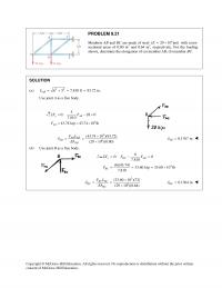
Copyright © McGraw–Hill Education. All rights reserved. No reproduction or distribution without the prior written consent of McGraw–Hill Education. PROBLEM 10.21 A torque of magnitude 100 N mT= ⋅ is applied to shaft AB of the gear train shown. Knowing […]

978-0073398167 Chapter 10 Solution Manual Part 4
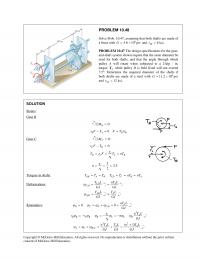
consent of McGraw–Hill Education. PROBLEM 10.29 The torques shown are exerted on pulleys A and B. Knowing that the shafts are solid and made of steel (G = 77.2 GPa), determine the angle of twist between (a) A and B, […]
978-0073398167 Chapter 10 Solution Manual Part 5
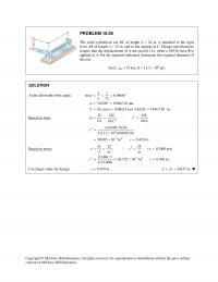
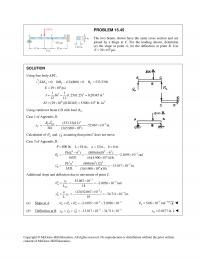
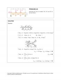
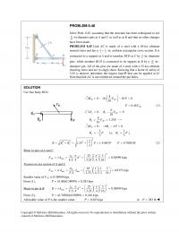
consent of McGraw–Hill Education. PROBLEM 10.39 The solid cylindrical rod BC of length L = 24 in. is attached to the rigid lever AB of length a = 15 in. and to the support at C. Design specifications require that […]
978-0073398167 Chapter 10 Solution Manual Part 6
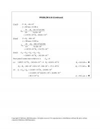
consent of McGraw–Hill Education. Gear B. 0: B MΣ= 0/ B A BB rF T F T r−= = Gear C. 0: C MΣ= 0 CD C DC A B B rF T r T r F T nT r […]
978-0073398167 Chapter 10 Solution Manual Part 7
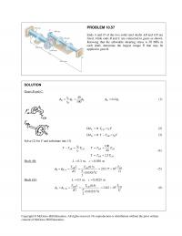
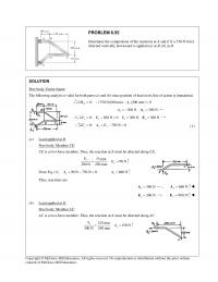
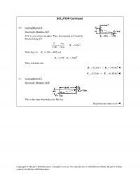
consent of McGraw–Hill Education. PROBLEM 10.57 Ends A and D of the two solid steel shafts AB and CD are fixed, while ends B and C are connected to gears as shown. Knowing that the allowable shearing stress is 50 […]
978-0073398167 Chapter 11 Solution Manual Part 1
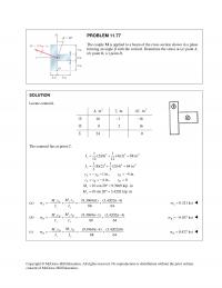
consent of McGraw–Hill Education. For rectangle: 12 I bh= Outside rectangle: 3 1 1(80)(120) 12 I= 6 4 64 111.52 10 mm 11.52 10 mI− =×=× Cutout: 3 21(40)(80) 12 I= 6 4 64 2 1.70667 10 mm 1.70667 10 […]
978-0073398167 Chapter 11 Solution Manual Part 10
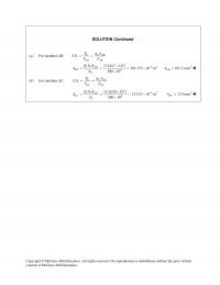
consent of McGraw–Hill Education. SOLUTION Continued Intersection of neutral axis with line BD or its extension. 0 0.9 in., ? 900 540 (800)( 2) O= 7.2 1.944 9.6 41.6667 277.778 0 0.15 in. y z zy zz Mz My Py […]
978-0073398167 Chapter 11 Solution Manual Part 11
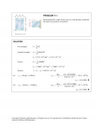
consent of McGraw–Hill Education. SOLUTION 34 64 11 (0.120 m)(0.06 m) 2 (0.02 m) 12 12 4 2.1391 10 mm − = −⋅ = × I π (a) 3 64 (2.8 10 N m)(0.03 m) 2.1391 10 […]
978-0073398167 Chapter 11 Solution Manual Part 12
consent of McGraw–Hill Education. The maximum stress occurs at point B. 3 15 ksi 15 10 psi B BP Mc P Pec KP AI AI s s =− =−× =−− =−− =− where 2 3 34 11.0 in. (0.5)(0.5) 0.25 […]
978-0073398167 Chapter 11 Solution Manual Part 2
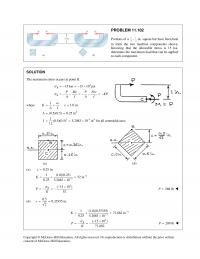
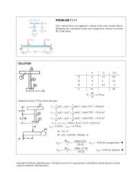
consent of McGraw–Hill Education. PROBLEM 11.11 Two vertical forces are applied to a beam of the cross section shown. Determine the maximum tensile and compressive stresses in portion BC of the beam. SOLUTION A 0 y 0 Ay 8 […]
978-0073398167 Chapter 11 Solution Manual Part 3
consent of McGraw–Hill Education. 600 32.5 19.5 10× 500 12.5 3 6.25 10× Σ 1100 3 25.75 10 × 3 025.75 10 23.41 mm The neutral axis lies 23.41 mm above the bottom. 1100 Y× = = top […]
978-0073398167 Chapter 11 Solution Manual Part 4
consent of McGraw–Hill Education. Use wood as the reference material. 1.0 in wood / 29/2 14.5 in steel sw n n EE = = = = For the transformed section, 32 1 1 11 1 11 324 2 34 2 […]
978-0073398167 Chapter 11 Solution Manual Part 5
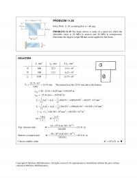
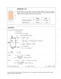
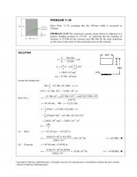
consent of McGraw–Hill Education. PROBLEM 11.40 Solve Prob. 11.39, assuming that the 300–mm width is increased to 350 mm. PROBLEM 11.39 The reinforced concrete beam shown is subjected to a positive bending moment of 175 kN ⋅ m. Knowing that […]
978-0073398167 Chapter 11 Solution Manual Part 6
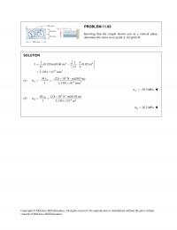
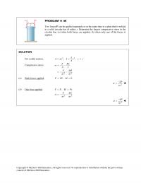
consent of McGraw–Hill Education. PROBLEM 11.49 Two forces P can be applied separately or at the same time to a plate that is welded to a solid circular bar of radius r. Determine the largest compressive stress in the circular […]
978-0073398167 Chapter 11 Solution Manual Part 7
consent of McGraw–Hill Education. (a) Centric loading: 4 in. × 4 in. cross section (4)(4) 16 inA= = 12 16 P A σ =−=− 0.75 ksi σ = − (b) Eccentric loading: 4 in. × 3 in. cross section […]
978-0073398167 Chapter 11 Solution Manual Part 8
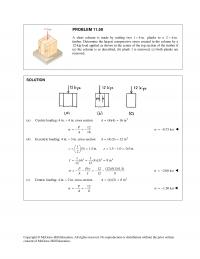
consent of McGraw–Hill Education. PROBLEM 11.67 A vertical force P of magnitude 20 kips is applied at point C located on the axis of symmetry of the cross section of a short column. Knowing that 5 in.,y= determine (a) the […]
978-0073398167 Chapter 11 Solution Manual Part 9
consent of McGraw–Hill Education. Locate centroid. 2 , inA , in.z 3 , inAz 16 −1 −16 8 2 16 Σ 24 0 The centroid lies at point C. 3 34 3 34 11 (2)(8) (4)(2) 88 in […]
978-0073398167 Chapter 12 Solution Manual Part 1
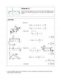
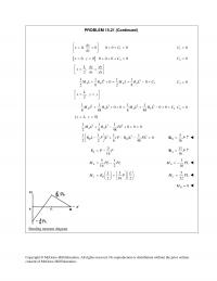
PROBLEM 12.1 For the beam and loading shown, (a) draw the shear and bending–moment diagrams, (b) determine the equations of the shear and bending–moment curves. SOLUTION 2 consent of McGraw–Hill Education. Reactions: 0: 0 C Pb M LA bP A […]
978-0073398167 Chapter 12 Solution Manual Part 10
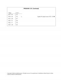
Copyright © McGraw–Hill Education. All rights reserved. No reproduction or distribution without the prior written PROBLEM 12.76 (Continued) Shape 3 (in )S W27 84× 213 W24 68× 154 ← Lightest W-shaped section: W24 68× W21 101× 227 W18 76× […]
978-0073398167 Chapter 12 Solution Manual Part 11
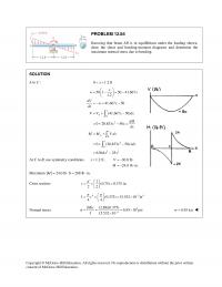
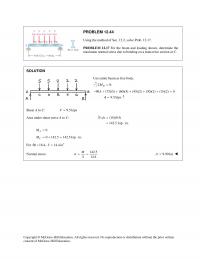
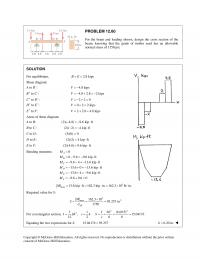
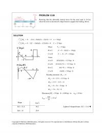
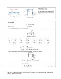
Copyright © McGraw–Hill Education. All rights reserved. No reproduction or distribution without the prior written PROBLEM 12.84 Knowing that beam AB is in equilibrium under the loading shown, draw the shear and bending–moment diagrams and determine the maximum normal stress […]
978-0073398167 Chapter 12 Solution Manual Part 2
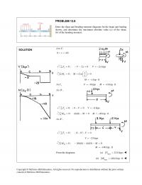
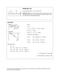
Copyright © McGraw–Hill Education. All rights reserved. No reproduction or distribution without the prior written PROBLEM 12.8 Draw the shear and bending–moment diagrams for the beam and loading shown, and determine the maximum absolute value (a) of the shear, (b) […]
978-0073398167 Chapter 12 Solution Manual Part 3
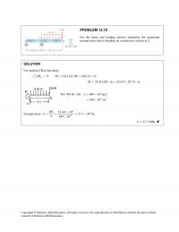
Use portion CB as free body. 3 0: (3)(2.1)(1.05) (8)(2.1) 0 23.415 kN m 23.415 10 N m C MM M Σ = −+ + = = ⋅= × ⋅ For 33 63 W310 60, 844 10 mm 844 10 […]
978-0073398167 Chapter 12 Solution Manual Part 4
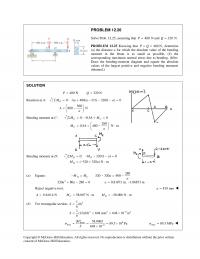
obtained.) SOLUTION 480 N 320 NPQ= = Reaction at A: 0: 480( 0.5) 320(1 ) 0 560 800 N D M Aa a a Aa Σ = + − − −= = − Bending moment at C: […]
978-0073398167 Chapter 12 Solution Manual Part 5
Shear: 0 0 (4)(2) 8 kips A B BA A V V V wdx = =− =−=− ∫ C to D: 8 kipsV= − D to B: 8 15 23 kipsV=−− =− Areas under shear diagram: A to C: 1(4)( […]
978-0073398167 Chapter 12 Solution Manual Part 6
Use entire beam as free body. 0: B MΣ= 90 (75)(5) (60)(5) (45)(2) (30)(2) (15)(2) 0 9.5 kips A−+ + + + + = = ↑A Shear A to C: 9.5 kipsV= Area under shear curve A to C: (15)(9.5) […]
978-0073398167 Chapter 12 Solution Manual Part 7
Bending moments: 0 A M= 0 2.0 2.0 kN m C M=−=− ⋅ 2.0 7.0417 5.0417 kN m D M=−+ = ⋅ 5.0417 5.0417 0 B M=−= Maximum 3 5.0417 kN m 5.0417 10 N mM= ⋅= × ⋅ Copyright […]
978-0073398167 Chapter 12 Solution Manual Part 8
For equilibrium, 2.8 kipsBE= = Shear diagram: A to B−: 4.8 kipsV= − B+ to C−: 4.8 2.8 2 kipsV=−+ =− C+ to D−: 220V=−+ = D+ to E−: 0 2 2 kipsV=+= E+ to F: 2 2.8 4.8 kipsV=+= […]
978-0073398167 Chapter 12 Solution Manual Part 9
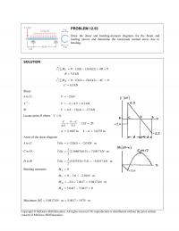
select the most economical S-shape beam to support the loading shown. SOLUTION 0: 12 (9)(6)(3) (3)(18) 0 9 kips C MA A ∑= −+ − = = 0: 12 (3)(6)(3) (15)(18) 0 27 kips A MC C∑= − − = […]
978-0073398167 Chapter 13 Solution Manual Part 1
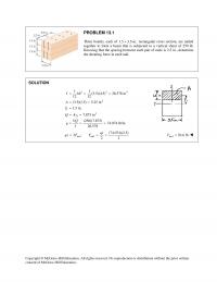
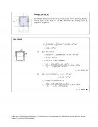
Copyright © McGraw–Hill Education. All rights reserved. No reproduction or distribution without the prior written consent of McGraw–Hill Education. PROBLEM 13.1 Three boards, each of 1.5 3.5-in. × rectangular cross section, are nailed together to form a beam that is […]
978-0073398167 Chapter 13 Solution Manual Part 2
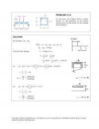
Copyright © McGraw–Hill Education. All rights reserved. No reproduction or distribution without the prior written PROBLEM 13.10 For the beam and loading shown, consider section n-n and determine (a) the largest shearing stress in that section, (b) the shearing stress […]
978-0073398167 Chapter 13 Solution Manual Part 3
Copyright © McGraw–Hill Education. All rights reserved. No reproduction or distribution without the prior written PROBLEM 13.20 For the beam and loading shown, determine the largest shearing stress in section n–n. SOLUTION 25 kips AB RR= = At section n–n, […]
978-0073398167 Chapter 13 Solution Manual Part 4
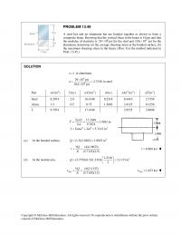
PROBLEM 13.30 (a) point a, (b) point b. SOLUTION 3 3 64 64 11 (80)(80) (56)(68) 1.9460 10 mm 12 12 1.946 10 m I − =−=× = × (a) 11 2 2 33 63 2 (56)(6)(37) (2)(12)(40)(20) 31.632 10 […]
978-0073398167 Chapter 13 Solution Manual Part 5
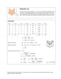
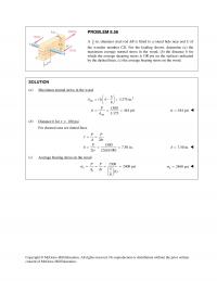
PROBLEM 13.40 A beam consists of five planks of 1.5 6-in. × cross section connected by steel bolts with a longitudinal spacing of 9 in. Knowing that the shear in the beam is vertical and equal to 2000 lb and […]
978-0073398167 Chapter 13 Solution Manual Part 6
1n= in aluminum. 6 6 29 10 psi 2.7358 10.6 10 psi n× = = × in steel. Part 2 (in )nA (in.)y 3 (in )nAy (in.)d 22 (in )nAd 4 (in )nI Steel 8.2074 2.0 16.4148 0.2318 0.4410 2.7358 […]
978-0073398167 Chapter 13 Solution Manual Part 7
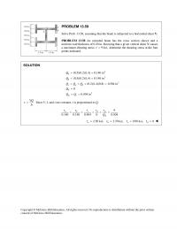
points indicated. SOLUTION 3 3 3 3 (0.5)(0.2)(1.4) 0.140 in (0.5)(0.2)(1.4) 0.140 in (0.2)(1.4)(0.8) 0.504 in 0 0.504 in a b c ab d mc Q Q QQQ Q QQ = = = = =++ = = = = VQ […]
978-0073398167 Chapter 14 Solution Manual Part 1
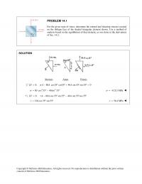
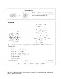
PROBLEM 14.1 For the given state of stress, determine the normal and shearing stresses exerted on the oblique face of the shaded triangular element shown. Use a method of analysis based on the equilibrium of that element, as was done […]
978-0073398167 Chapter 14 Solution Manual Part 2
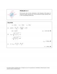
Copyright © McGraw–Hill Education. All rights reserved. No reproduction or distribution without the prior written PROBLEM 14.11 For the given state of stress, determine (a) the orientation of the planes of maximum in–plane shearing stress, (b) the maximum in–plane shearing […]
978-0073398167 Chapter 14 Solution Manual Part 3
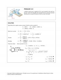
PROBLEM 14.21 A 400–lb vertical force is applied at D to a gear attached to the solid l–in. diameter shaft AB. Determine the principal stresses and the maximum shearing stress at point H located as shown on top of the […]
978-0073398167 Chapter 14 Solution Manual Part 4
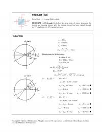
Copyright © McGraw–Hill Education. All rights reserved. No reproduction or distribution without the prior written consent of McGraw–Hill Education. PROBLEM 14.30 Solve Prob. 14.14, using Mohr’s circle. PROBLEM 14.13 through 14.16 For the given state of stress, determine the normal […]
978-0073398167 Chapter 14 Solution Manual Part 5
PROBLEM 14.39 Solve Prob. 14.23, using Mohr’s circle. PROBLEM 14.23 The steel pipe AB has a 102–mm outer diameter and a 6–mm wall thickness. Knowing that arm CD is rigidly attached to the pipe, determine the principal stresses and 3 […]
978-0073398167 Chapter 14 Solution Manual Part 6
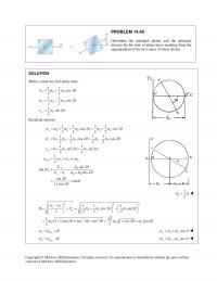
PROBLEM 14.48 Determine the principal planes and the principal stresses for the state of plane stress resulting from the superposition of the two states of stress shown. SOLUTION Mohr’s circle for 2nd stress state: 00 00 0 11 cos 2 […]
978-0073398167 Chapter 14 Solution Manual Part 7
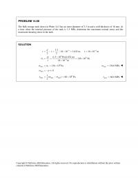
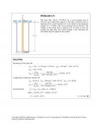
Copyright © McGraw–Hill Education. All rights reserved. No reproduction or distribution without the prior written PROBLEM 14.58 The bulk storage tank shown in Photo 14.3 has an outer diameter of 3.3 m and a wall thickness of 18 mm. At […]
978-0073398167 Chapter 14 Solution Manual Part 8
Copyright © McGraw–Hill Education. All rights reserved. No reproduction or distribution without the prior written PROBLEM 14.67 (Continued) ave 1( ) 35.69 MPa 2xy σ σσ = += 2 2 9.40 MPa 2 xy xy R σσ τ − […]
978-0073398167 Chapter 14 Solution Manual Part 9
hk θ θθ ≤≤ uv 45 98.13 θ °≤ ≤ ° Also, 135 188.13 and 225 278.13 θθ °≤ ≤ ° °≤ ≤ ° Copyright © McGraw–Hill Education. All rights reserved. No reproduction or distribution without the prior written […]
978-0073398167 Chapter 15 Solution Manual Part 1
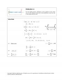
PROBLEM 15.1 For the loading shown, determine (a) the equation of the elastic curve for the cantilever beam AB, (b) the deflection at the free end, (c) the slope at the free end. SOLUTION 0: ( ) 0 J M […]
978-0073398167 Chapter 15 Solution Manual Part 2
Data: 60 10 N,P= × 26.9 10 mm 26.9 10 mI =×=× 9 200 10 PaE= × 62 5.38 10 N mEI =×⋅ 2mL= (a) 32 6 (60 10 )(2) (16)(5.38 10 ) A θ × =× 3 2.79 10 […]
978-0073398167 Chapter 15 Solution Manual Part 3
PROLEM 15.14 (Continued) 33 3 11 [ , 0] Eq. (4): ( ) 0 66 P x L y bL L L a C L L = = − −+= 32 32 13 1 1 11 () […]
978-0073398167 Chapter 15 Solution Manual Part 4
Copyright © McGraw–Hill Education. All rights reserved. No reproduction or distribution without the prior written PROBLEM 15.21 (Continued) 1 0, 0 0 0 0 dy xC dx = = ++ = 10C= [ ] 2 0, 0000 […]
978-0073398167 Chapter 15 Solution Manual Part 5
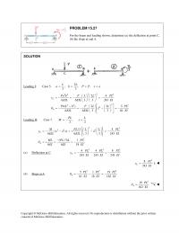
SOLUTION Loading I: Case 5. 2 , ,, 33 LL a b PPxa= = = = 22 22 3 2 22 2 2 24 6 6 3 3 243 () 2 2 5 6 6 3 3 81 C A […]
978-0073398167 Chapter 15 Solution Manual Part 6
PROBLEM 15.36 (Continued) Slope at B. 3 15 6.98 10 2148 B θ − = = × 3 6.98 10 rad B θ − = × Deflection at B. 3 28.125 13.09 10 ft 2148 B y − =− […]
978-0073398167 Chapter 15 Solution Manual Part 7
PROBLEM 15.45 The two beams shown have the same cross section and are joined by a hinge at C. For the loading shown, determine (a) the slope at point A, (b) the deflection at point B. Use 6 SOLUTION Using […]
978-0073398167 Chapter 15 Solution Manual Part 8
PROBLEM 15.53 Knowing that beam AE is an S200 27.4× rolled shape and that 17.5 kN, 2.5 m, 0.8 mP La= = = and 200 GPa, E= determine (a) the equation of the elastic curve for portion BD, (b) the […]
978-0073398167 Chapter 15 Solution Manual Part 9
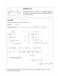
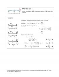
Copyright © McGraw–Hill Education. All rights reserved. No reproduction or distribution without the prior written PROBLEM 15.60 For the uniform beam shown, determine the reaction at each of the three supports. SOLUTION Consider C R as redundant and replace loading […]
978-0073398167 Chapter 16 Solution Manual Part 1
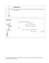
Let θ be the angle change of bar AB. sinF kx kL θ = = 2 0: cos 0 sin cos sin 0 B M FL Px kL PL θ θθ θ Σ = −= −= Using 2 sin and […]
978-0073398167 Chapter 16 Solution Manual Part 2
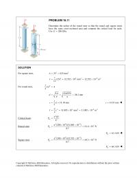
Copyright © McGraw–Hill Education. All rights reserved. No reproduction or distribution without the prior written PROBLEM 16.11 Determine the radius of the round strut so that the round and square struts have the same cross–sectional area and compute the critical […]
978-0073398167 Chapter 16 Solution Manual Part 3
PROBLEM 16.21 Column ABC has a uniform rectangular cross section and is braced in the xz plane at its midpoint C. (a) Determine the ratio b/d for which the factor of safety is the same with respect to buckling in […]
978-0073398167 Chapter 16 Solution Manual Part 4
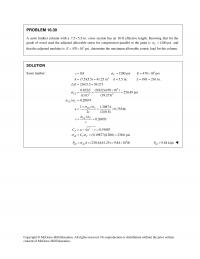
Sawn lumber: 2 0.8 1200 psi 470 10 psi (7.5)(5.5) 41.25 in 5.5 in. 18ft 216 in. / 216/5.5 39.273 C cE A dL Ld = = = × = = = = = = = s 3 22 0.822 […]
978-0073398167 Chapter 16 Solution Manual Part 5
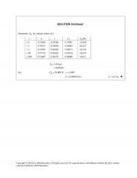
SOLUTION Continued Determine all P for various values of x. x u v P C all (lb)P 1.0 0.73620 0.22240 0.17087 12,920 1.2 0.78513 0.32026 0.24092 26,227 1.1 0.75955 0.26910 0.20473 18,729 1.09 0.75712 0.26423 0.20124 18,075 1.089 0.75687 0.26374 […]
978-0073398167 Chapter 16 Solution Manual Part 6
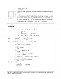
PROBLEM 16.47 Solve Prob. 16.46, assuming that the effective length of the column is decreased to 20 ft. PROBLEM 16.46 A square structural tube having the cross section shown is used as a column of 26–ft effective length to carry […]
978-0073398167 Chapter 16 Solution Manual Part 7
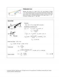
PROBLEM 16.54 Member AB consists of a single C130 10.4 × steel channel of length 2.5 m. Knowing that the pins at A and B pass through the centroid of the cross section of the channel, determine the factor of […]
978-0073398167 Chapter 2 Solution Manual Part 1
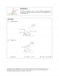
(a) Parallelogram law: (b) Triangle rule: We measure: 1391 kN, 47.8R α = = ° 1391 N=R 47.8° Copyright © McGraw–Hill Education. This is proprietary material solely for authorized instructor use. Not authorized for sale or distribution in any […]
978-0073398167 Chapter 2 Solution Manual Part 10
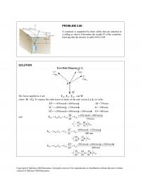
PROBLEM 2.86 Three wires are connected at point D, which is located 18 in. below the T–shaped pipe support ABC. Determine the tension in each wire when a 180–lb cylinder is suspended from point D as shown. SOLUTION Free–Body Diagram […]
978-0073398167 Chapter 2 Solution Manual Part 11
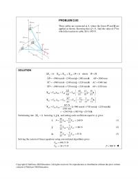
Copyright © McGraw–Hill Education. All rights reserved. No reproduction or distribution without the prior written PROBLEM 2.92 Three cables are connected at A, where the forces P and Q are applied as shown. Knowing that 0,Q= find the value of […]
978-0073398167 Chapter 2 Solution Manual Part 12
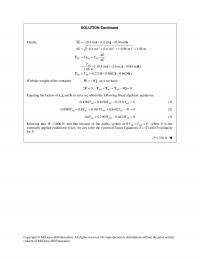
With the weight of the container ,W= −Wj at A we have: 0: 0 AB AC AD WΣ= + + − =F TTT j Equating the factors of i, j, and k to zero, we obtain the following linear algebraic […]
978-0073398167 Chapter 2 Solution Manual Part 13
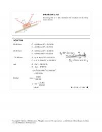
Copyright © McGraw–Hill Education. All rights reserved. No reproduction or distribution without the prior written consent of McGraw–Hill Education. PROBLEM 2.107 Knowing that a = 40°, determine the resultant of the three forces shown. SOLUTION 60-lb Force: (60 lb)cos20 56.382 […]
978-0073398167 Chapter 2 Solution Manual Part 2
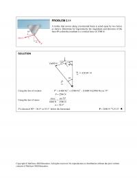
PROBLEM 2.11 A trolley that moves along a horizontal beam is acted upon by two forces as shown. Determine by trigonometry the magnitude and direction of the force P so that the resultant is a vertical force of 2500 N. […]
978-0073398167 Chapter 2 Solution Manual Part 3
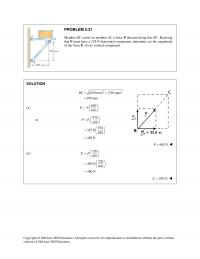
Copyright © McGraw–Hill Education. All rights reserved. No reproduction or distribution without the prior written PROBLEM 2.21 Member BC exerts on member AC a force P directed along line BC. Knowing that P must have a 325–N horizontal component, determine […]
978-0073398167 Chapter 2 Solution Manual Part 4
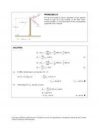
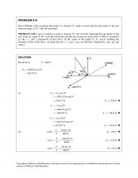
(a) For R to be horizontal, we must have 0. R= Copyright © McGraw–Hill Education. All rights reserved. No reproduction or distribution without the prior written consent of McGraw–Hill Education. PROBLEM 2.31 For the post loaded as shown, determine (a) […]
978-0073398167 Chapter 2 Solution Manual Part 5
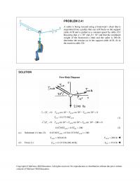
Copyright © McGraw–Hill Education. All rights reserved. No reproduction or distribution without the prior written consent of McGraw–Hill Education. PROBLEM 2.41 A sailor is being rescued using a boatswain’s chair that is suspended from a pulley that can roll freely […]
978-0073398167 Chapter 2 Solution Manual Part 6
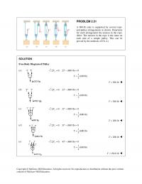
Copyright © McGraw–Hill Education. All rights reserved. No reproduction or distribution without the prior written PROBLEM 2.51 A 600–lb crate is supported by several rope- and–pulley arrangements as shown. Determine for each arrangement the tension in the rope. (Hint: The […]
978-0073398167 Chapter 2 Solution Manual Part 7
Copyright © McGraw–Hill Education. All rights reserved. No reproduction or distribution without the prior written consent of McGraw–Hill Education. PROBLEM 2.61 Solve Problem 2.60, assuming that point A is located 15° north of west and that the barrel of the […]
978-0073398167 Chapter 2 Solution Manual Part 8
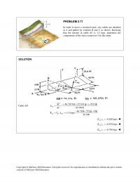
Copyright © McGraw–Hill Education. All rights reserved. No reproduction or distribution without the prior written consent of McGraw–Hill Education. PROBLEM 2.71 In order to move a wrecked truck, two cables are attached at A and pulled by winches B and […]
978-0073398167 Chapter 2 Solution Manual Part 9
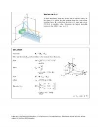
where .W=Wj To express the other forces in terms of the unit vectors i, j, k, we write (450 mm) (600 mm) 750 mm (600 mm) (320 mm) 680 mm (500 mm) (600 mm) (360 mm) 860 mm AB AB […]
978-0073398167 Chapter 3 Solution Manual Part 1
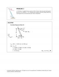
Copyright © McGraw–Hill Education. All rights reserved. No reproduction or distribution without the prior written PROBLEM 3.1 A 20–lb force is applied to the control rod AB as shown. Knowing that the length of the rod is 9 in. and […]
978-0073398167 Chapter 3 Solution Manual Part 10
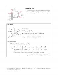
PROBLEM 3.87 A machine component is subjected to the forces shown, each of which is parallel to one of the coordinate axes. Replace these forces with an equivalent force–couple system at A. SOLUTION Copyright © McGraw–Hill Education. All rights reserved. […]
978-0073398167 Chapter 3 Solution Manual Part 11
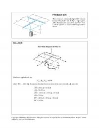
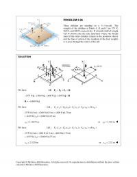
Copyright © McGraw–Hill Education. All rights reserved. No reproduction or distribution without the prior written PROBLEM 3.96 Three children are standing on a 5 5-m raft.× The weights of the children at Points A, B, and C are 375 N, […]
978-0073398167 Chapter 3 Solution Manual Part 12
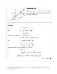
Let the coordinates of Point P be (x in., y in., z in.). Then The requirement that OA and PC be perpendicular implies that Copyright © McGraw–Hill Education. All rights reserved. No reproduction or distribution without the prior written PROBLEM […]
978-0073398167 Chapter 3 Solution Manual Part 2
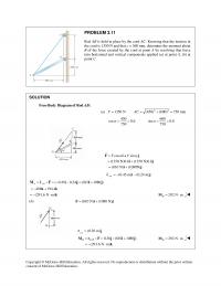
PROBLEM 3.11 Rod AB is held in place by the cord AC. Knowing that the tension in the cord is 1350 N and that c = 360 mm, determine the moment about B of the force exerted by the cord […]
978-0073398167 Chapter 3 Solution Manual Part 3
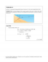
Copyright © McGraw–Hill Education. All rights reserved. No reproduction or distribution without the prior written PROBLEM 3.21 In Prob. 3.15, determine the perpendicular distance from point A to a line drawn through points B and C. PROBLEM 3.15 A 6–ft–long […]
978-0073398167 Chapter 3 Solution Manual Part 4
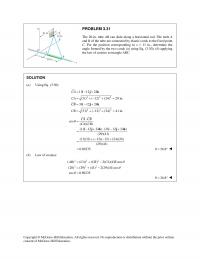
PROBLEM 3.31 The 20–in. tube AB can slide along a horizontal rod. The ends A and B of the tube are connected by elastic cords to the fixed point C. For the position corresponding to x = 11 in., determine […]
978-0073398167 Chapter 3 Solution Manual Part 5
Also note that only TAD will contribute to the moment about the z–axis. or max 61.5 lbT= Copyright © McGraw–Hill Education. All rights reserved. No reproduction or distribution without the prior written consent of McGraw–Hill Education. PROBLEM 3.41 A […]
978-0073398167 Chapter 3 Solution Manual Part 6
PROBLEM 3.49 Two parallel 60–N forces are applied to a lever as shown. Determine the moment of the couple formed by the two forces (a) by resolving each force into horizontal and vertical components and adding the moments of the […]
978-0073398167 Chapter 3 Solution Manual Part 7
SOLUTION Continued 123 (3.84 2.88 ) 2.40 ( 1.92 1.6 ) (1.92 N m) (1.44 N m) (1.28 N m) MM M M= + + = + − +− − =− ⋅+ ⋅+ ⋅ j k j ik ijk 222 […]
978-0073398167 Chapter 3 Solution Manual Part 8
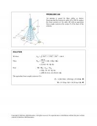
Copyright © McGraw–Hill Education. All rights reserved. No reproduction or distribution without the prior written PROBLEM 3.68 An antenna is guyed by three cables as shown. Knowing that the tension in cable AB is 288 lb, replace the force exerted […]
978-0073398167 Chapter 3 Solution Manual Part 9
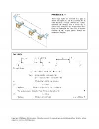
Copyright © McGraw–Hill Education. All rights reserved. No reproduction or distribution without the prior written consent of McGraw–Hill Education. PROBLEM 3.77 Three stage lights are mounted on a pipe as shown. The lights at A and B each weigh 4.1 […]
978-0073398167 Chapter 4 Solution Manual Part 1
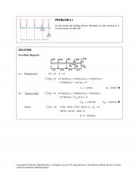
PROBLEM 4.1 For the beam and loading shown, determine (a) the reaction at A, (b) the tension in cable BC. SOLUTION Free–Body Diagram: (a) Reaction at A: 0: 0 xx FAΣ= = 0: (15 lb)(28 in.) (20 lb)(22 in.) (35 […]
978-0073398167 Chapter 4 Solution Manual Part 10
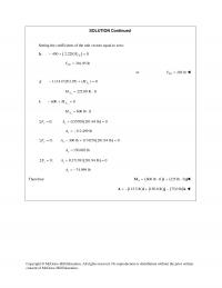
SOLUTION Continued Setting the coefficients of the unit vectors equal to zero: ( ) : 450 2.2283 0 CE F−+ =k 201.95 lb CE F= or 202 lb CE F= : 1.11417(201.95) ( ) 0 A M− +=j y 225.00 […]
978-0073398167 Chapter 4 Solution Manual Part 11
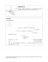
PROBLEM 4.78 Determine whether the block shown is in equilibrium and find the magnitude and direction of the friction force when P = 80 lb. SOLUTION Assume equilibrium: 0: (50 lb)sin 30 (80 lb)cos 40 0 x FFΣ = + […]
978-0073398167 Chapter 4 Solution Manual Part 12
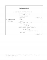
SOLUTION Continued 0: (32 in.) (12 in.) (24 in.) 0 AB M PW NΣ= + − = 8 3 6 0 0.25 0.3 P PW P W +− = = tip ( 0.25 OK)P WP= < 0.25(120 lb)P= or 30.0 […]
978-0073398167 Chapter 4 Solution Manual Part 13
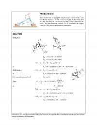
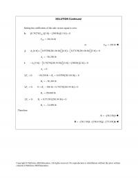
PROBLEM 4.95 Two slender rods of negligible weight are pin-connected at C and attached to blocks A and B, each of weight W. Knowing that 80 θ = ° and that the coefficient of static friction between the blocks and […]
978-0073398167 Chapter 4 Solution Manual Part 14
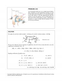
PROBLEM 4.103 Two transmission belts pass over a double–sheaved pulley that is attached to an axle supported by bearings at A and D. The radius of the inner sheave is 125 mm and the radius of the outer sheave is […]
978-0073398167 Chapter 4 Solution Manual Part 2
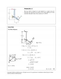
Copyright © McGraw–Hill Education. All rights reserved. No reproduction or distribution without the prior written PROBLEM 4.11 The lever BCD is hinged at C and attached to a control rod at B. Determine the maximum force P that can be […]
978-0073398167 Chapter 4 Solution Manual Part 3
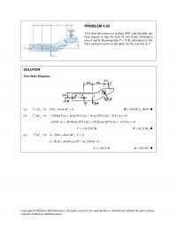
PROBLEM 4.20 Two slots have been cut in plate DEF, and the plate has been placed so that the slots fit two fixed, frictionless pins A and B. Knowing that P = 15 lb, determine (a) the force each pin […]
978-0073398167 Chapter 4 Solution Manual Part 4
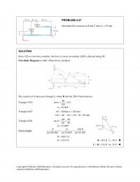
PROBLEM 4.27 Determine the reactions at B and C when a = 30 mm. Copyright © McGraw–Hill Education. All rights reserved. No reproduction or distribution without the prior written SOLUTION Since CD is a two–force member, the force it exerts […]
978-0073398167 Chapter 4 Solution Manual Part 5
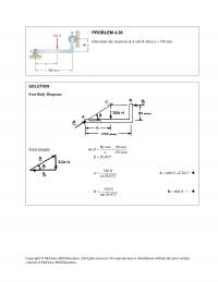
Copyright © McGraw–Hill Education. All rights reserved. No reproduction or distribution without the prior written PROBLEM 4.36 Determine the reactions at A and B when a = 150 mm. SOLUTION Free–Body Diagram: Force triangle 80 mm 80 mm tan 150 […]
978-0073398167 Chapter 4 Solution Manual Part 6
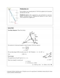
PROBLEM 4.45 Solve Problem 4.44, assuming that the 170–N force applied at B is horizontal and directed to the left. PROBLEM 4.44 Rod AB is supported by a pin and bracket at A and rests against a frictionless peg at […]
978-0073398167 Chapter 4 Solution Manual Part 7
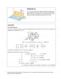
propped against column CD. It rests at A and B on small wooden blocks and against protruding nails. Neglecting friction at all surfaces of contact, determine the reactions at A, B, and C. Equating the coefficients of the unit vectors […]
978-0073398167 Chapter 4 Solution Manual Part 8
SOLUTION Continued Coefficient of j: 240 240 0 13 17 BD TT−+ = 17 17 (520) 680 lb 13 13 BD BD TT T= = = 0: 320 0 AD AE BF CΣ= + + − + =F TTT j […]
978-0073398167 Chapter 4 Solution Manual Part 9
Setting the coefficients of the unit vectors equal to zero: Copyright © McGraw–Hill Education. All rights reserved. No reproduction or distribution without the prior written SOLUTION Continued ( ) ( ) ( )( ) : 0.74278 3 ft 300 lb […]
978-0073398167 Chapter 5 Solution Manual Part 1
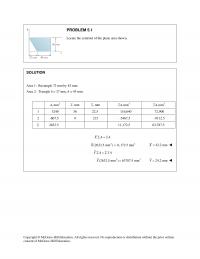
Area 1: Rectangle 72 mm by 45 mm. Area 2: Triangle b = 27 mm, h = 45 mm. 2 , mmA , mmx , mmy 3 ,mmxA 3 ,mmyA 1 3240 36 22.5 116,640 72,900 2 -607.5 9 215 […]
978-0073398167 Chapter 5 Solution Manual Part 10
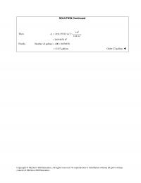
SOLUTION Continued Then 2 22 1ft 2 2 (1.25312 in. ) 144 in. 0.054678 ft s A π = × = Finally Number of gallons 400 0.054678= × 21.87 gallons= Order 22 gallons consent of McGraw–Hill Education. Copyright © […]
978-0073398167 Chapter 5 Solution Manual Part 2
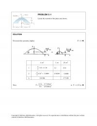
Locate the centroid of the plane area shown. Copyright © McGraw–Hill Education. All rights reserved. No reproduction or distribution without the prior written PROBLEM 5.11 SOLUTION First note that symmetry implies 0X= 2 ,mA ,my 3 ,myA 1 44.5 […]
978-0073398167 Chapter 5 Solution Manual Part 3
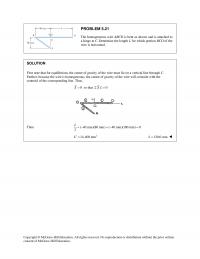
PROBLEM 5.21 The homogeneous wire ABCD is bent as shown and is attached to a hinge at C. Determine the length L for which portion BCD of the wire is horizontal. First note that for equilibrium, the center of gravity […]
978-0073398167 Chapter 5 Solution Manual Part 4
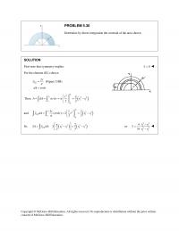
Copyright © McGraw–Hill Education. All rights reserved. No reproduction or distribution without the prior written PROBLEM 5.30 Determine by direct integration the centroid of the area shown. SOLUTION First note that symmetry implies 0x= For the element (EL) shown […]
978-0073398167 Chapter 5 Solution Manual Part 5
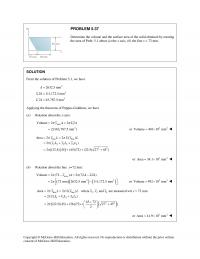
Determine the volume and the surface area of the solid obtained by rotating the area of Prob. 5.1 about (a) the x axis, (b) the line x = 72 mm. Copyright © McGraw–Hill Education. All rights reserved. No reproduction or […]
978-0073398167 Chapter 5 Solution Manual Part 6
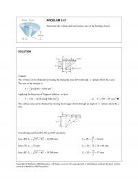
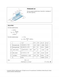
Volume: The volume can be obtained by rotating the triangular area shown through π radians about the y axis. The area of the triangle is: ( )( ) 2 152 60 1560 mm 2 A= = Applying the theorems of […]
978-0073398167 Chapter 5 Solution Manual Part 7
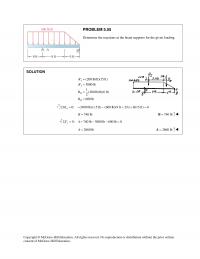
Copyright © McGraw–Hill Education. All rights reserved. No reproduction or distribution without the prior written consent of McGraw–Hill Education. PROBLEM 5.55 Determine the reactions at the beam supports for the given loading. SOLUTION I I II II (200 lb/ft)(15 ft) […]
978-0073398167 Chapter 5 Solution Manual Part 8
I Rectangular plate (5.25)(3)(0.5) 7.875= 0.25− 2.625 1.9688− 20.672 II Rectangular plate (3)(1.5)(0.75) 3.375= 0.75 1.5 2.5313 5.0625 III –(Half cylinder) 2 (0.95) (0.75) 1.063 2 π −=− 1.097 1.5 1.1664− 1.595− IV Half cylinder 2 (1.5) (0.5) 1.767 2 […]
978-0073398167 Chapter 5 Solution Manual Part 9
Copyright © McGraw–Hill Education. All rights reserved. No reproduction or distribution without the prior written consent of McGraw–Hill Education. PROBLEM 5.72 A brass collar, of length 2.5 in., is mounted on an aluminum rod of length 4 in. Locate the […]
978-0073398167 Chapter 6 Solution Manual Part 1
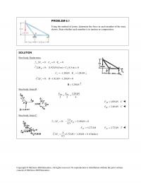
PROBLEM 6.1 Using the method of joints, determine the force in each member of the truss shown. State whether each member is in tension or compression. SOLUTION Free body: Entire truss 0: 0 0 x xx FCΣ= = =C 0: […]
978-0073398167 Chapter 6 Solution Manual Part 10
8 15 17 17 25 15 17 17 25 5 15 3 r r CD r CD CD r r += = = = From Eq. (1): 55 (4.5 in.) 33 7.5 in. CF r […]
978-0073398167 Chapter 6 Solution Manual Part 11
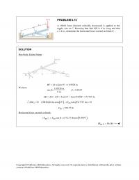
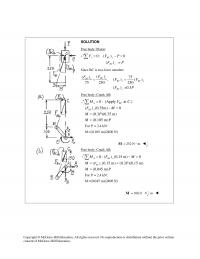
PROBLEM 6.73 A 100–lb force directed vertically downward is applied to the toggle vise at C. Knowing that link BD is 6 in. long and that a = 4 in., determine the horizontal force exerted on block E. SOLUTION Free […]
978-0073398167 Chapter 6 Solution Manual Part 12
Free body: Piston: 0 : ( ) 0 ( ) = y BC y BC y F FP FP = −= ∑ Since BC is two–force member: () () 75 , () () 75 250 250 ( ) =0.3 BC […]
978-0073398167 Chapter 6 Solution Manual Part 13
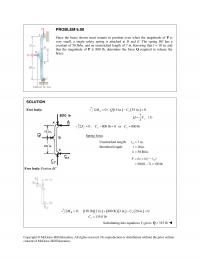
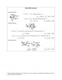
PROBLEM 6.90 Since the brace shown must remain in position even when the magnitude of P is very small, a single safety spring is attached at D and E. The spring DE has a constant of 50 lb/in. and an […]
978-0073398167 Chapter 6 Solution Manual Part 14
SOLUTION Continued Free body: Joint B: 0: (800 lb)cos16.26 0 y BC FFΣ = − − °= 768.0 lb 768 lb BC BC F FC=−= 0: 3613.8 lb (800 lb) sin16.26° 0 x BD FF Σ= + + = […]
978-0073398167 Chapter 6 Solution Manual Part 15
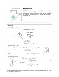
PROBLEM 6.106 A 3–ft–diameter pipe is supported every 16 ft by a small frame like that shown. Knowing that the combined weight of the pipe and its contents is 500 lb/ft and assuming frictionless surfaces, determine the components (a) of […]
978-0073398167 Chapter 6 Solution Manual Part 2
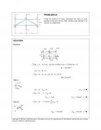
PROBLEM 6.8 Using the method of joints, determine the force in each member of the truss shown. State whether each member is in tension or compression. SOLUTION Reactions: 0: (3 m) (24 kN 8 kN)(1.5 m) (7 kN)(3 m) 0 […]
978-0073398167 Chapter 6 Solution Manual Part 3
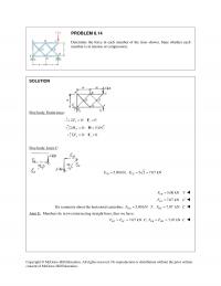
PROBLEM 6.14 Determine the force in each member of the truss shown. State whether each member is in tension or compression. SOLUTION Free body: Entire truss: 0: 0 xx FΣ= =F 0: 5 kN F MΣ= =H 0: 0 yy […]
978-0073398167 Chapter 6 Solution Manual Part 4
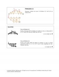
Starting with triangle EHK and adding two members at a time, we obtain successively joints D, J, C, G, I, B, F, and A, thus completing the truss. Therefore, this truss Copyright © McGraw–Hill Education. All rights reserved. No reproduction […]

978-0073398167 Chapter 6 Solution Manual Part 5
Copyright © McGraw–Hill Education. All rights reserved. No reproduction or distribution without the prior written PROBLEM 6.29 Determine the force in members DE and DF of the truss shown when P = 20 kips. SOLUTION Reactions: 2.5P= =CK 7.5 tan […]
978-0073398167 Chapter 6 Solution Manual Part 6
Copyright © McGraw–Hill Education. All rights reserved. No reproduction or distribution without the prior written PROBLEM 6.39 Determine the force in members AD, CD, and CE of the truss shown. SOLUTION Reactions: 0: 9 kips(8 ft) (45 ft) 5 kips(30 […]
978-0073398167 Chapter 6 Solution Manual Part 7
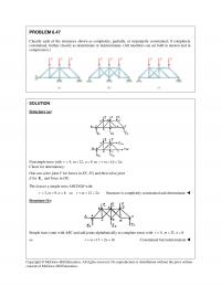
Nonsimple truss with 4,r= 12,m= 8n= so 16 2 .rm n+= = Check for determinacy: One can solve joint F for forces in EF, FG and then solve joint E for y E and force in DE. This leaves a […]
978-0073398167 Chapter 6 Solution Manual Part 8
CE is a two-force member. Thus, the reaction at E must be directed along CE. 75 mm 90 N 300 N 250 mm yy EE= = From Eq. (1): 90 N 750 N 0 y A+− = 660 N y […]
978-0073398167 Chapter 6 Solution Manual Part 9
SOLUTION Continued (b) Load applied at D. Free body: Member ACF. directed along CF. 7 in. 14 lb 32 lb 16 in. From Eq. (1): 14 lb 48 lb 0 y B+−= 34 lb 34 lb yy BB= = Thus, […]
978-0073398167 Chapter 7 Solution Manual Part 1
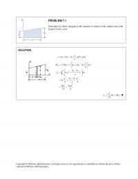
Copyright © McGraw–Hill Education. All rights reserved. No reproduction or distribution without the prior written PROBLEM 7.1 Determine by direct integration the moment of inertia of the shaded area with respect to the y axis. SOLUTION 1 21 ( ); […]
978-0073398167 Chapter 7 Solution Manual Part 2
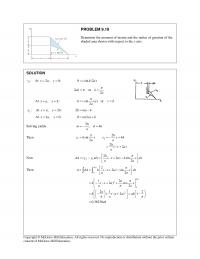
PROBLEM 9.10 Determine the moment of inertia and the radius of gyration of the shaded area shown with respect to the x axis. Then 12 2 sin 4 22( 2) h yh x y xh aa hxa a π = […]
978-0073398167 Chapter 7 Solution Manual Part 3
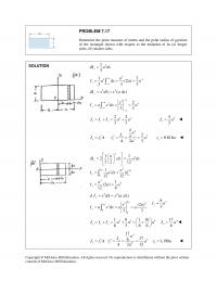
PROBLEM 7.17 Determine the polar moment of inertia and the polar radius of gyration Copyright © McGraw–Hill Education. All rights reserved. No reproduction or distribution without the prior written consent of McGraw–Hill Education. of the rectangle shown with respect to […]
978-0073398167 Chapter 7 Solution Manual Part 4
Copyright © McGraw–Hill Education. All rights reserved. No reproduction or distribution without the prior written consent of McGraw–Hill Education. PROBLEM 7.25 Determine the moment of inertia and the radius of gyration of the shaded area with respect to the x […]
978-0073398167 Chapter 7 Solution Manual Part 5
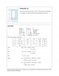
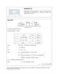
Copyright © McGraw–Hill Education. All rights reserved. No reproduction or distribution without the prior written consent of McGraw–Hill Education. PROBLEM 7.35 Determine the moments of inertia x I and y I of the area shown with respect to centroidal axes […]
978-0073398167 Chapter 7 Solution Manual Part 6
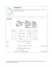
1 (4.5) 15.904 4 = 1.9099 30.375 2 2 (3) 7.069 4 π −=− 1.2732 –9.00 Σ 8.835 21.375 Copyright © McGraw–Hill Education. All rights reserved. No reproduction or distribution without the prior written PROBLEM 7.40 Determine the polar moment […]
978-0073398167 Chapter 7 Solution Manual Part 7
SOLUTION Continued Also 2() () y yL yC II I= + where 2 64 2 2 64 ( ) 0.512 10 mm (929 mm )[(127 21.2) mm] 10.9109 10 mm () yL y yC y I I Ad II =+= […]
978-0073398167 Chapter 7 Solution Manual Part 8
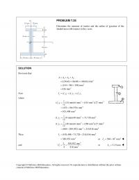
1 108 60 6480×= 54 349,920 2 172 36 1296 2 −× × =− 46 –59,616 Σ 5184 290,304 Then 23 : (5184 mm ) 290,304 mmX A xA XΣ=Σ = or 56.0 mmX= Now 12 () () xx x […]
978-0073398167 Chapter 8 Solution Manual Part 1
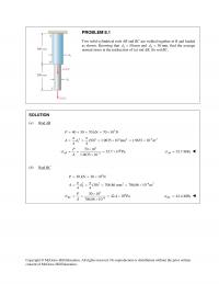
Copyright © McGraw–Hill Education. All rights reserved. No reproduction or distribution without the prior written PROBLEM 8.1 Two solid cylindrical rods AB and BC are welded together at B and loaded as shown. Knowing that 150d= mm and 2 30d= […]
978-0073398167 Chapter 8 Solution Manual Part 2
Use piston, rod, and crank together as free body. Add wall reaction H and bearing reactions Ax and Ay. 3 0 : (0.280 m) 1500 N m 0 5.3571 10 N Σ = − ⋅= = × A MH H […]
978-0073398167 Chapter 8 Solution Manual Part 3
(a) Shearing stress in pin at C. 2 τ =BC P F A 22 2 (0.8) 0.5026 in 44 8.9658 8.92 (2)(0.5026) P Ad ππ τ = = = = = 8.92 ksi τ = Copyright © McGraw–Hill Education. […]
978-0073398167 Chapter 8 Solution Manual Part 4
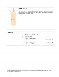
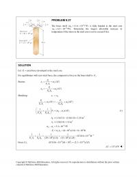
Copyright © McGraw–Hill Education. All rights reserved. No reproduction or distribution without the prior written consent of McGraw–Hill Education. PROBLEM 8.27 The 1.4–kip load P is supported by two wooden members of uniform cross section that are joined by the […]
978-0073398167 Chapter 8 Solution Manual Part 5
SOLUTION Continued (a) For member AB: F.S. U U AB AB AB PA FF σ = = 362 6 (F.S.) (3.2)(17 10 ) 181.333 10 m 300 10 AB AB U F A σ − × = = = × […]
978-0073398167 Chapter 8 Solution Manual Part 6
Copyright © McGraw–Hill Education. All rights reserved. No reproduction or distribution without the prior written consent of McGraw–Hill Education. PROBLEM 8.46 Solve Prob. 8.45, assuming that the structure has been redesigned to use 5 16 –in–diameter pins at A and […]
978-0073398167 Chapter 8 Solution Manual Part 7
For sheared area see dotted lines. Copyright © McGraw–Hill Education. All rights reserved. No reproduction or distribution without the prior written PROBLEM 8.56 A 5 8 –in.–diameter steel rod AB is fitted to a round hole near end C of […]
978-0073398167 Chapter 9 Solution Manual Part 1
Copyright © McGraw–Hill Education. All rights reserved. No reproduction or distribution without the prior written PROBLEM 9.1 A 4.8-ft–long steel wire of 1 4 -in.-diameter is subjected to a 750-lb tensile load. Knowing that E = 29 × 106 psi, […]
978-0073398167 Chapter 9 Solution Manual Part 10
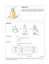
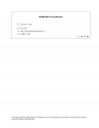
Copyright © McGraw–Hill Education. All rights reserved. No reproduction or distribution without the prior written PROBLEM 9.79 (Continued) 1() 2 bb bb P AA σσ = + ( )1.5 bb PA σ = 6 (80 10 Pa)(0.04 m)(0.06 m)(1.5)= ×P […]
978-0073398167 Chapter 9 Solution Manual Part 2
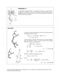
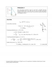
Copyright © McGraw–Hill Education. All rights reserved. No reproduction or distribution without the prior written PROBLEM 9.11 The 4–mm–diameter cable BC is made of a steel with 200 GPa.=E Knowing that the maximum stress in the cable must not exceed […]
978-0073398167 Chapter 9 Solution Manual Part 3
Members AB and BC are made of steel ( 29 10 psi)E= × with cross– sectional areas of 0.80 in2 and 0.64 in2, respectively. For the loading shown, determine the elongation of (a) member AB, (b) member BC. Copyright © […]
978-0073398167 Chapter 9 Solution Manual Part 4
PROBLEM 9.30 (Continued) C to D: 3 60 10 100 mm 0.100 m = −× = = A PR L 3 6 96 ( 60 10 )(0.100) 74.220 10 1.34735 10 80.841 10 δ −− −× = = × = […]
978-0073398167 Chapter 9 Solution Manual Part 5
For equilibrium with zero total force, the compressive force in the brass shell is . P Copyright © McGraw–Hill Education. All rights reserved. No reproduction or distribution without the prior written PROBLEM 9.37 The brass shell 6 ( 11.6 10 […]
978-0073398167 Chapter 9 Solution Manual Part 6
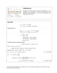
Copyright © McGraw–Hill Education. All rights reserved. No reproduction or distribution without the prior written PROBLEM 9.45 Knowing that a 0.02–in. gap exists when the temperature is 75 F,° determine (a) the temperature at which the normal stress in the […]
978-0073398167 Chapter 9 Solution Manual Part 7
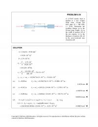
Copyright © McGraw–Hill Education. All rights reserved. No reproduction or distribution without the prior written PROBLEM 9.54 A 2.75 –kN tensile load is applied to a test coupon made from 1.6 –mm flat steel plate (E = 200 GPa, v […]
978-0073398167 Chapter 9 Solution Manual Part 8
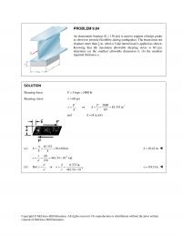
determine (a) the smallest allowable dimension b, (b) the smallest required thickness a. SOLUTION Shearing force: 5 kips 5000 lbP= = Shearing stress: 60 psi τ = 2 5000 , or 83.333 in 60 = = = = PP A […]
978-0073398167 Chapter 9 Solution Manual Part 9
Copyright © McGraw–Hill Education. All rights reserved. No reproduction or distribution without the prior written consent of McGraw–Hill Education. PROBLEM 9.74 The brass tube ( 105 GPa)AB E = has a cross–sectional area of 140 mm2 and is fitted with […]