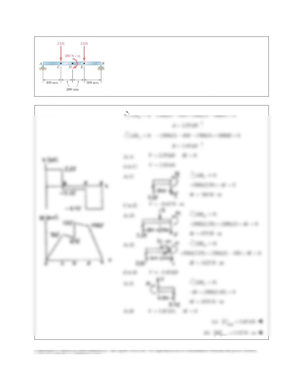
PROBLEM 12.9
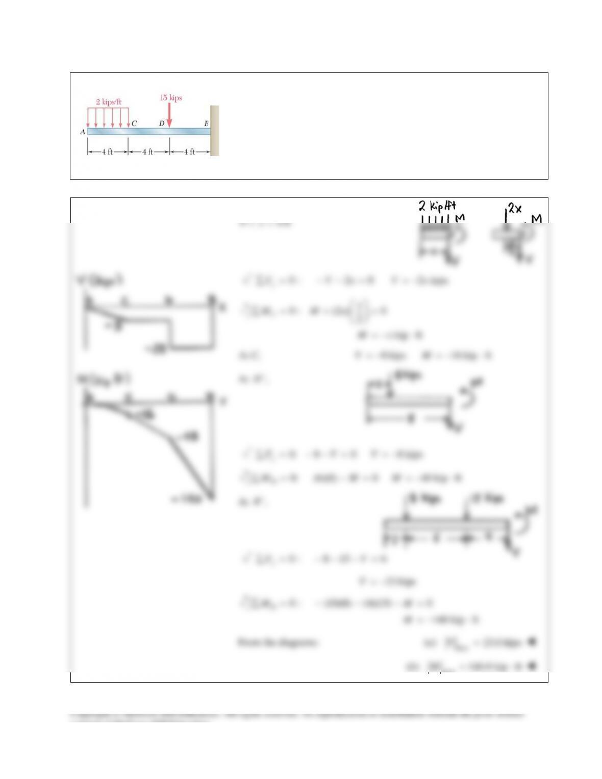
Draw the shear and bending-moment diagrams for the beam and loading
shown, and determine the maximum absolute value (a) of the shear,
(b) of the bending moment.
SOLUTION
0: (700)(3) 450 (300)(3) 1000 0
B
MAΣ= − + − =
2.55 kNA=
0: (300)(3) 450 (700)(3) 1000 0
A
MBΣ= − − − + =
3.45 kNB=
At A:
2.55 kN 0VM= =
A to C:
2.55 kNV=
At C:
0:
C
MΣ=
(300)(2.55) 0M− +=
765 N m
M= ⋅
C to E:
0.45 N mV=−⋅
At D:
0:
D
M
Σ=
(500)(2.55) (200)(3) 0M− + +=
675 N mM= ⋅
At D:
0:
D
MΣ=
(500)(2.55) (200)(3) 450 0M− + − +=
1125 N mM= ⋅
E to B:
3.45 kNV= −
At E:
0:
E
MΣ=
(300)(3.45) 0M−+ =
1035 N mM= ⋅
At B:
3.45 kN, 0VM= =
(a)
max
3.45 kNV=
(b)
max
1125 N mM= ⋅
consent of McGraw–Hill Education.
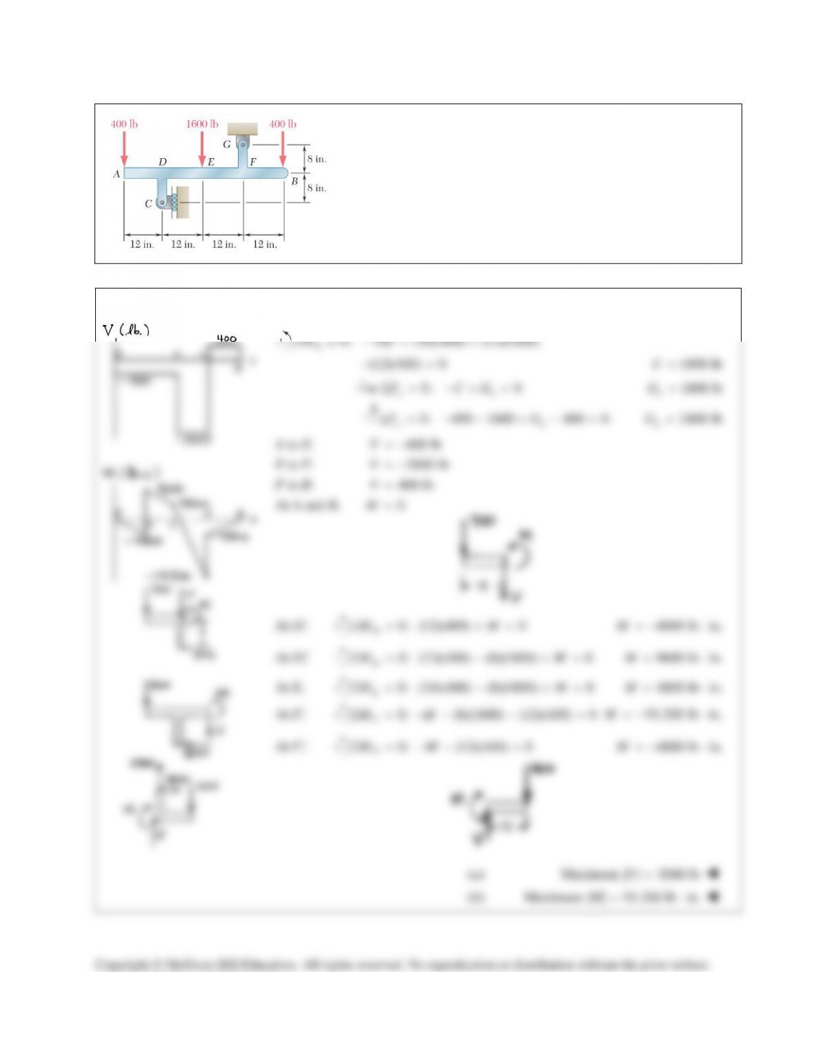
PROBLEM 12.10
Draw the shear and bending–moment diagrams for the beam and
loading shown, and determine the maximum absolute value (a) of
the shear, (b) of the bending moment.
SOLUTION
0: 16 (36)(400) (12)(1600)
G
MC
Σ=− + +
(12)(400) 0−=
1800 lbC=
0: 0
xx
F CGΣ = −+ =
1800 lb
x
G=
0: 400 1600 400 0
yy
FGΣ= − − + − =
2400 lb
y
G=
A to E:
400 lbV= −
E to F:
2000 lbV= −
F to B:
400 lbV=
At A and B,
0M=
At
,
D
−
0: (12)(400) 0
D
MMΣ = +=
4800 lb in.M=−⋅
At
+
,
D
0:
D
MΣ=
(12)(400) (8)(1800) 0M− +=
9600 lb in.M= ⋅
At E,
0: (24)(400) (8)(1800) 0
E
MM
Σ = − +=
4800 lb in.
M= ⋅
At
,
F
−
0: (8)(1800) (12)(400) 0
F
MMΣ = −− − =
19,200 lb in.M=−⋅
At
+
,
F
0: (12)(400) 0
F
MM
Σ = −− =
4800 lb in.
M=−⋅
(a) Maximum
| | 2000 lbV=
(b) Maximum
| | 19,200 lb in.M= ⋅
Copyright © McGraw–Hill Education. All rights reserved. No reproduction or distribution without the prior written
consent of McGraw–Hill Education.
PROBLEM 12.11
Assuming that the reaction of the ground is uniformly distributed, draw
the shear and bending–moment diagrams for the beam AB and determine
the maximum absolute value (a) of the shear, (b) of the bending moment.
SOLUTION
consent of McGraw–Hill Education.
PROBLEM 12.12
Assuming that the reaction of the ground is uniformly distributed, draw
the shear and bending–moment diagrams for the beam AB and determine
the maximum absolute value (a) of the shear, (b) of the bending
moment.
SOLUTION
Over the whole beam,
0: 1.5 1.5 1.5 0
y
FwΣ= − − =
2 kN/mw=
A to C:
0 0.3 mx≤<
0: 2 0
y
F xVΣ= −=
(2 ) kNVx=
0: (2 ) 0
2
J
x
M xM
Σ= − +=
2
( ) kN mMx= ⋅
At
,
C
−
0.3 mx=
0.6 kN, 0.090 kN m
90 N m
VM= = ⋅
= ⋅
C to D:
0.3 m 1.2 mx<<
0: 2 1.5 0
y
F xVΣ= − −=
(2 1.5) kNVx= −
0: (2 ) (1.5)( 0.3) 0
2
J
x
M x xM
Σ= − + − +=
2
( 1.5 0.45) kN mMx x=−+ ⋅
At the center of the beam,
0.75 mx=
0 0.1125 kN m
112.5 N m
VM
= =−⋅
=−⋅
At
+
,
C
0.3 m, 0.9 kNxV= = −
(a) Maximum
| | 0.9 kN 900 NV= =
(b) Maximum
| | 112.5 N mM= ⋅
Copyright © McGraw–Hill Education. All rights reserved. No reproduction or distribution without the prior written
consent of McGraw–Hill Education.
PROBLEM 12.13
For the beam and loading shown, determine the maximum
normal stress due to bending on a transverse section at C.
SOLUTION
PROBLEM 12.14
For the beam and loading shown, determine the maximum
normal stress due to bending on a transverse section at C.
SOLUTION
PROBLEM 12.15
For the beam and loading shown, determine the maximum normal
stress due to bending on section a-a.
SOLUTION
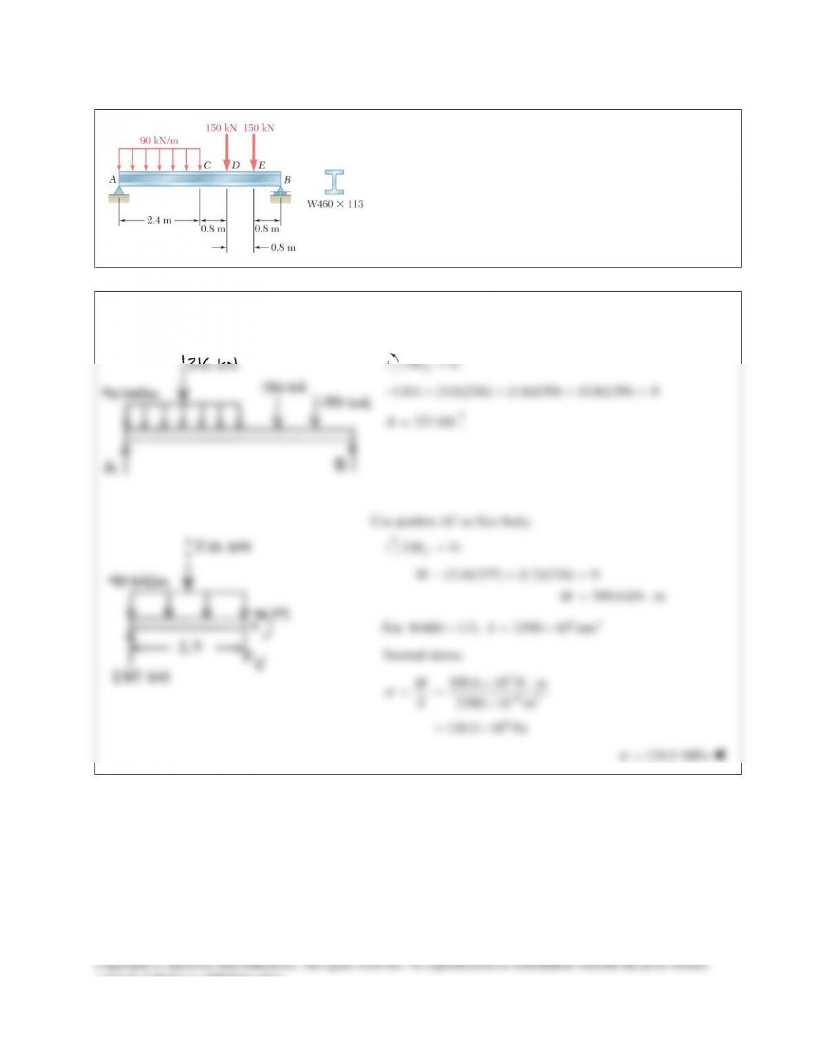
PROBLEM 12.16
For the beam and loading shown, determine the maximum
normal stress due to bending on a transverse section at C.
SOLUTION
Use entire beam as free body.
0:
B
MΣ=
4.8 (3.6)(216) (1.6)(150) (0.8)(150) 0A−+ + + =
237 kN=A
Use portion AC as free body.
0:
C
MΣ=
(2.4)(237) (1.2)(216) 0
309.6 kN m
M
M
−+=
= ⋅
For
63
W460 113, 2390 10 mmS×=×
Normal stress:
3
63
6
309.6 10 N m
2390 10 m
129.5 10 Pa
M
S
σ
−
×⋅
= = ×
= ×
129.5
σ
=
MPa
consent of McGraw–Hill Education.
PROBLEM 12.17
For the beam and loading shown, determine the maximum normal
stress due to bending on a transverse section at C.
SOLUTION
Use entire beam as free body.
0:
B
M∑=
90 (75)(5) (60)(5) (45)(2) (30)(2) (15)(2) 0A−+ + + + + =
9.5 kipsA=
Use portion AC as free body.
0: (15)(9.5) 0
142.5 kip in.
C
MM
M
Σ= − =
= ⋅
For
3
8 18.4, 14.4 inSS×=
Normal stress:
142.5
14.4
M
S
σ
= =
9.90 ksi
σ
=
consent of McGraw–Hill Education.
PROBLEM 12.9
Draw the shear and bending-moment diagrams for the beam and loading
shown, and determine the maximum absolute value (a) of the shear,
(b) of the bending moment.
SOLUTION
0: (700)(3) 450 (300)(3) 1000 0
B
MAΣ= − + − =
2.55 kNA=
0: (300)(3) 450 (700)(3) 1000 0
A
MBΣ= − − − + =
3.45 kNB=
At A:
2.55 kN 0VM= =
A to C:
2.55 kNV=
At C:
0:
C
MΣ=
(300)(2.55) 0M− +=
765 N m
M= ⋅
C to E:
0.45 N mV=−⋅
At D:
0:
D
M
Σ=
(500)(2.55) (200)(3) 0M− + +=
675 N mM= ⋅
At D:
0:
D
MΣ=
(500)(2.55) (200)(3) 450 0M− + − +=
1125 N mM= ⋅
E to B:
3.45 kNV= −
At E:
0:
E
MΣ=
(300)(3.45) 0M−+ =
1035 N mM= ⋅
At B:
3.45 kN, 0VM= =
(a)
max
3.45 kNV=
(b)
max
1125 N mM= ⋅
consent of McGraw–Hill Education.
PROBLEM 12.10
Draw the shear and bending–moment diagrams for the beam and
loading shown, and determine the maximum absolute value (a) of
the shear, (b) of the bending moment.
SOLUTION
0: 16 (36)(400) (12)(1600)
G
MC
Σ=− + +
(12)(400) 0−=
1800 lbC=
0: 0
xx
F CGΣ = −+ =
1800 lb
x
G=
0: 400 1600 400 0
yy
FGΣ= − − + − =
2400 lb
y
G=
A to E:
400 lbV= −
E to F:
2000 lbV= −
F to B:
400 lbV=
At A and B,
0M=
At
,
D
−
0: (12)(400) 0
D
MMΣ = +=
4800 lb in.M=−⋅
At
+
,
D
0:
D
MΣ=
(12)(400) (8)(1800) 0M− +=
9600 lb in.M= ⋅
At E,
0: (24)(400) (8)(1800) 0
E
MM
Σ = − +=
4800 lb in.
M= ⋅
At
,
F
−
0: (8)(1800) (12)(400) 0
F
MMΣ = −− − =
19,200 lb in.M=−⋅
At
+
,
F
0: (12)(400) 0
F
MM
Σ = −− =
4800 lb in.
M=−⋅
(a) Maximum
| | 2000 lbV=
(b) Maximum
| | 19,200 lb in.M= ⋅
Copyright © McGraw–Hill Education. All rights reserved. No reproduction or distribution without the prior written
consent of McGraw–Hill Education.
PROBLEM 12.11
Assuming that the reaction of the ground is uniformly distributed, draw
the shear and bending–moment diagrams for the beam AB and determine
the maximum absolute value (a) of the shear, (b) of the bending moment.
SOLUTION
consent of McGraw–Hill Education.
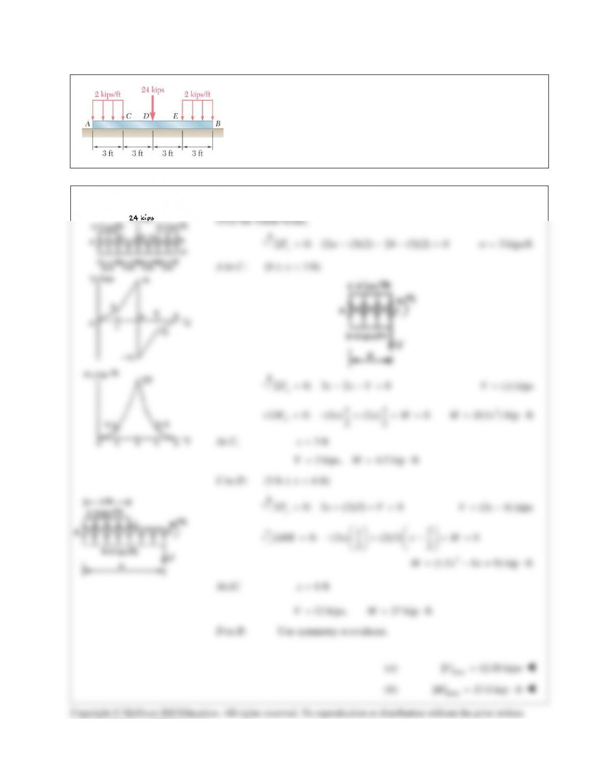
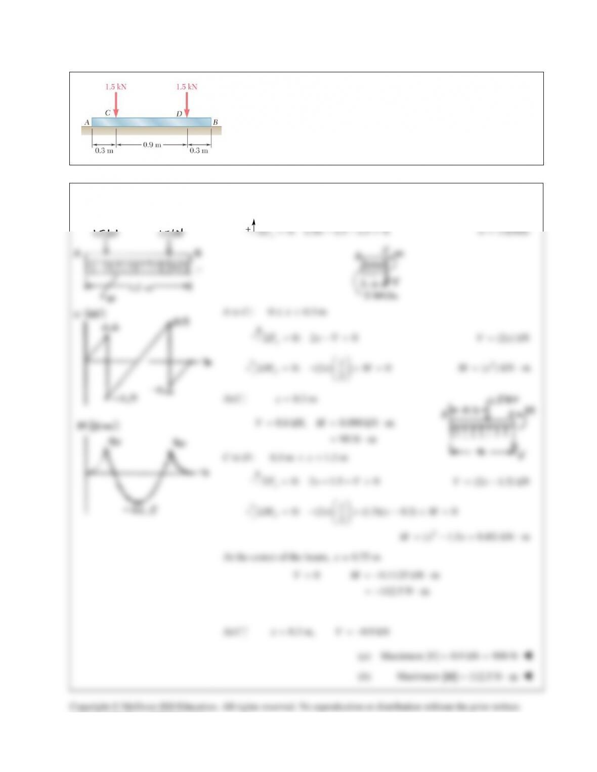
PROBLEM 12.12
Assuming that the reaction of the ground is uniformly distributed, draw
the shear and bending–moment diagrams for the beam AB and determine
the maximum absolute value (a) of the shear, (b) of the bending
moment.
SOLUTION
Over the whole beam,
0: 1.5 1.5 1.5 0
y
FwΣ= − − =
2 kN/mw=
A to C:
0 0.3 mx≤<
0: 2 0
y
F xVΣ= −=
(2 ) kNVx=
0: (2 ) 0
2
J
x
M xM
Σ= − +=
2
( ) kN mMx= ⋅
At
,
C
−
0.3 mx=
0.6 kN, 0.090 kN m
90 N m
VM= = ⋅
= ⋅
C to D:
0.3 m 1.2 mx<<
0: 2 1.5 0
y
F xVΣ= − −=
(2 1.5) kNVx= −
0: (2 ) (1.5)( 0.3) 0
2
J
x
M x xM
Σ= − + − +=
2
( 1.5 0.45) kN mMx x=−+ ⋅
At the center of the beam,
0.75 mx=
0 0.1125 kN m
112.5 N m
VM
= =−⋅
=−⋅
At
+
,
C
0.3 m, 0.9 kNxV= = −
(a) Maximum
| | 0.9 kN 900 NV= =
(b) Maximum
| | 112.5 N mM= ⋅
Copyright © McGraw–Hill Education. All rights reserved. No reproduction or distribution without the prior written
consent of McGraw–Hill Education.
PROBLEM 12.13
For the beam and loading shown, determine the maximum
normal stress due to bending on a transverse section at C.
SOLUTION
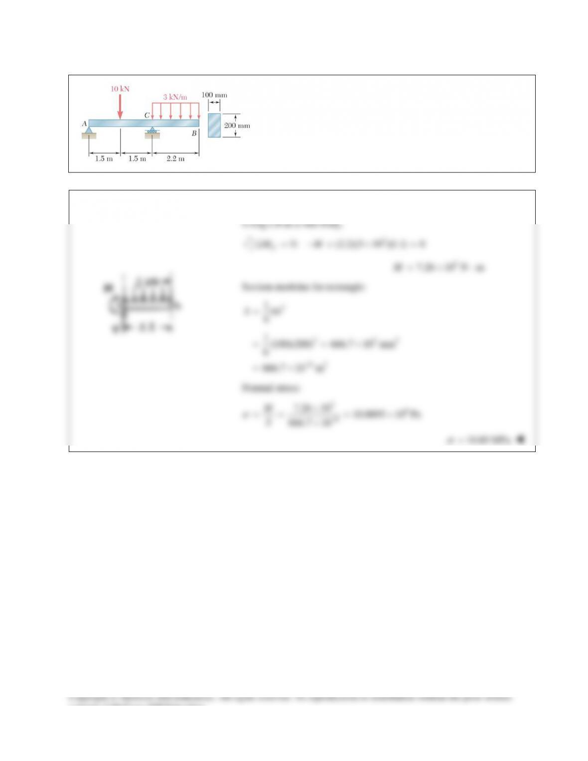
PROBLEM 12.14
For the beam and loading shown, determine the maximum
normal stress due to bending on a transverse section at C.
SOLUTION
PROBLEM 12.15
For the beam and loading shown, determine the maximum normal
stress due to bending on section a-a.
SOLUTION
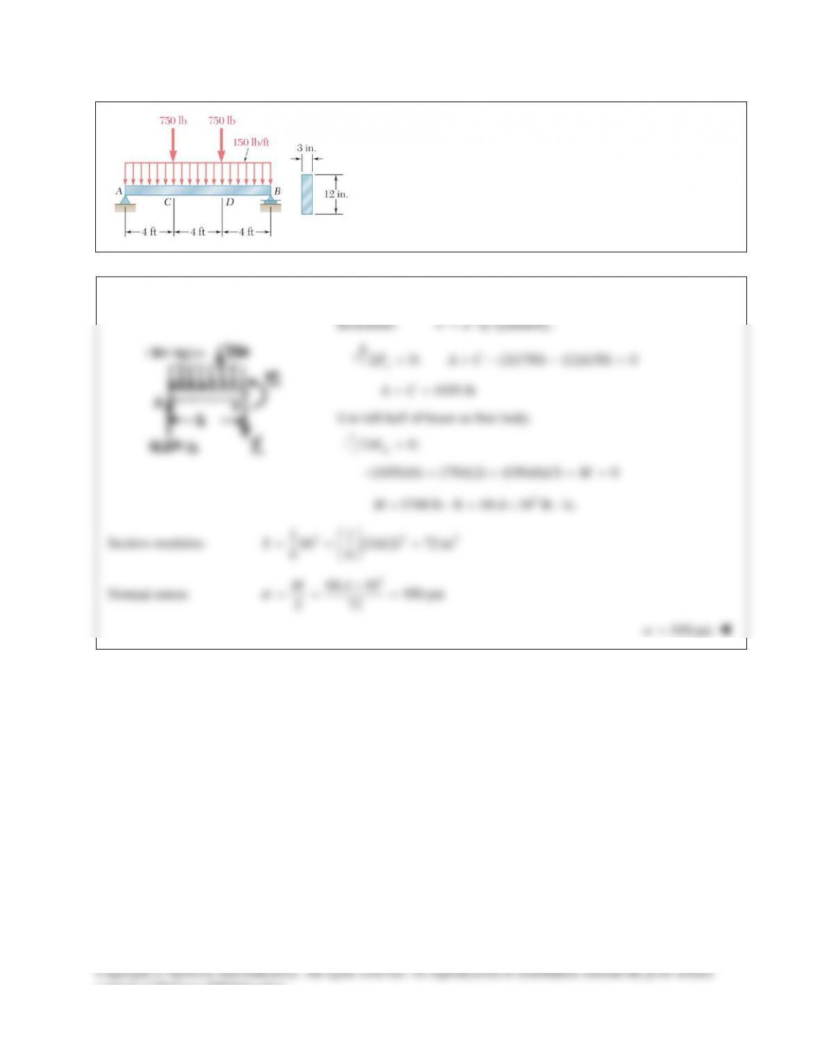
PROBLEM 12.16
For the beam and loading shown, determine the maximum
normal stress due to bending on a transverse section at C.
SOLUTION
Use entire beam as free body.
0:
B
MΣ=
4.8 (3.6)(216) (1.6)(150) (0.8)(150) 0A−+ + + =
237 kN=A
Use portion AC as free body.
0:
C
MΣ=
(2.4)(237) (1.2)(216) 0
309.6 kN m
M
M
−+=
= ⋅
For
63
W460 113, 2390 10 mmS×=×
Normal stress:
3
63
6
309.6 10 N m
2390 10 m
129.5 10 Pa
M
S
σ
−
×⋅
= = ×
= ×
129.5
σ
=
MPa
consent of McGraw–Hill Education.
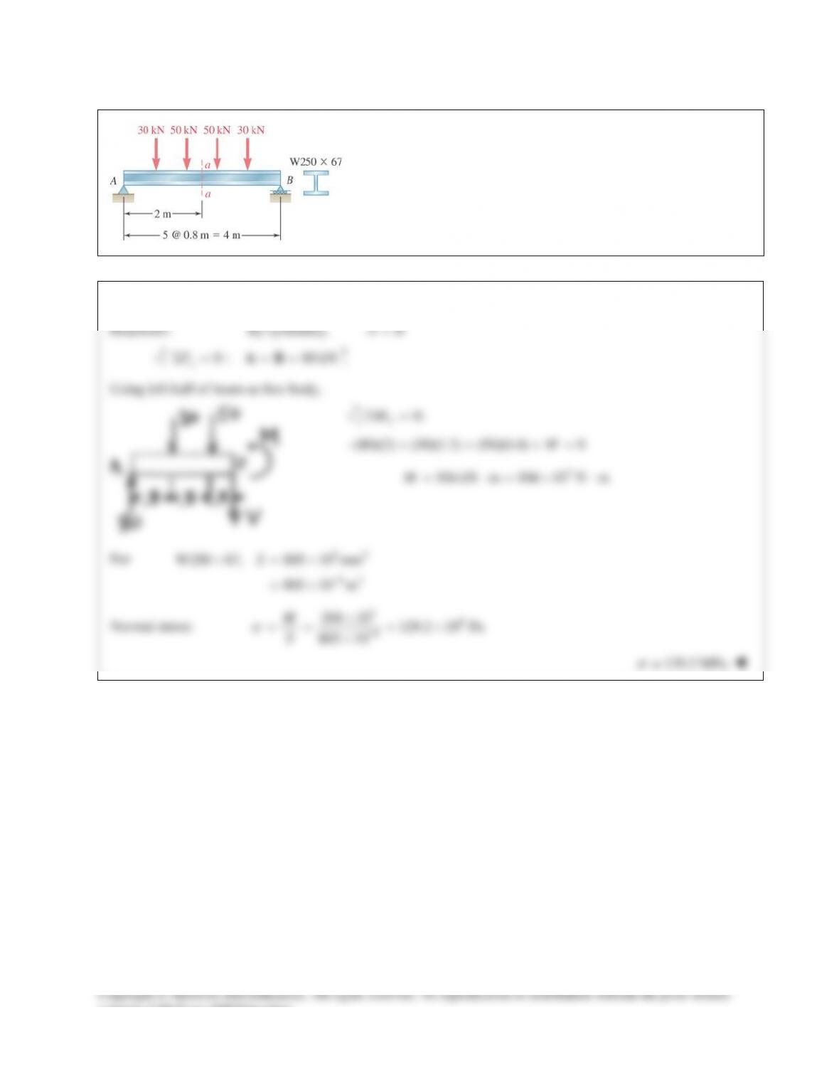
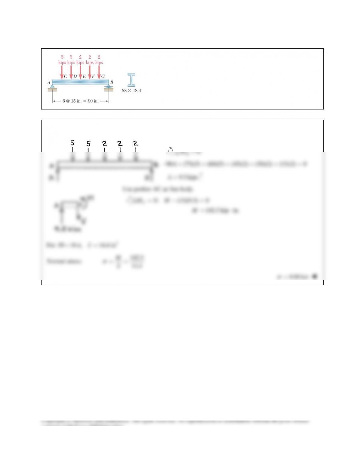
PROBLEM 12.17
For the beam and loading shown, determine the maximum normal
stress due to bending on a transverse section at C.
SOLUTION
Use entire beam as free body.
0:
B
M∑=
90 (75)(5) (60)(5) (45)(2) (30)(2) (15)(2) 0A−+ + + + + =
9.5 kipsA=
Use portion AC as free body.
0: (15)(9.5) 0
142.5 kip in.
C
MM
M
Σ= − =
= ⋅
For
3
8 18.4, 14.4 inSS×=
Normal stress:
142.5
14.4
M
S
σ
= =
9.90 ksi
σ
=
consent of McGraw–Hill Education.