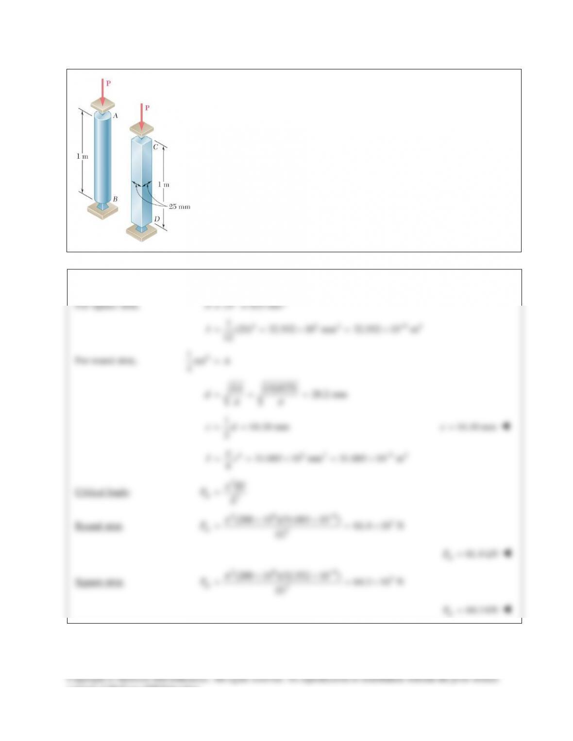
PROBLEM 16.12
A column of effective length L can be made by gluing together
identical planks in either of the arrangements shown. Determine the
ratio of the critical load using the arrangement a to the critical load
using the arrangement b.
SOLUTION
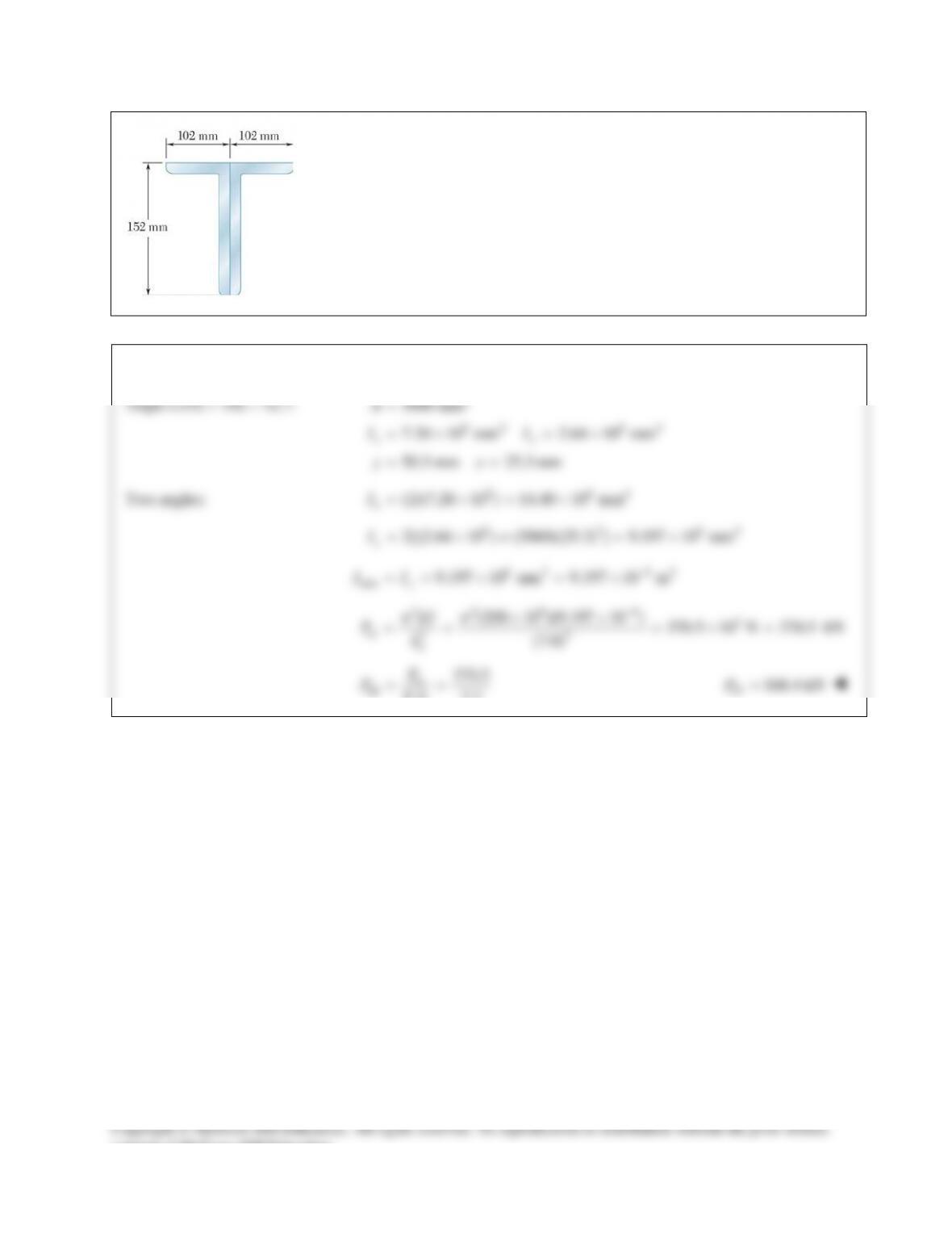
PROBLEM 16.13
A compression member of 7–m effective length is made by welding
together two
L152 102 12.7
××
angles as shown. Using
200 GPa,E=
determine the allowable centric load for the
member if a factor of safety of 2.2 is required.
SOLUTION
Angle L152 × 102 × 12.7:
2
64 64
3060 mm
7.20 10 mm 2.64 10 mm
50.3 mm 25.3 mm
xy
A
II
yx
=
=×=×
= =
Two angles:
6 64
(2)(7.20 10 ) 14.40 10 mm
x
I= ×= ×
6 2 64
2[(2.64 10 ) (3060)(25.3) ] 9.197 10 mm
y
I= ×+ = ×
6 4 64
min 9.197 10 mm 9.197 10 m
y
II −
==×=×
22 9 6 3
cr 22
(200 10 )(9.197 10 ) 370.5 10 N 370.5 kN
(7.0)
e
EI
PL
ππ
−
××
== =×=
cr
all
370.5
. . 2.2
P
PFS
= =
all 168.4 kNP=
consent of McGraw–Hill Education.
PROBLEM 16.14
A single compression member of 27–ft effective length is obtained by
connecting two C8 × 11.5 steel channels with lacing bars as shown.
Knowing that the factor of safety is 1.85, determine the allowable
centric load for the member. Use
6
29 10 psiE= ×
and
4.0 in.d=
SOLUTION
2
PROBLEM 16.15
A column of 22–ft effective length is to be made by welding two
9 0.5-in.×
plates to a W8 × 35 as shown. Determine the allowable
centric load if a factor of safety 2.3 is required. Use
6
29 10 psi.×
SOLUTION
4
4
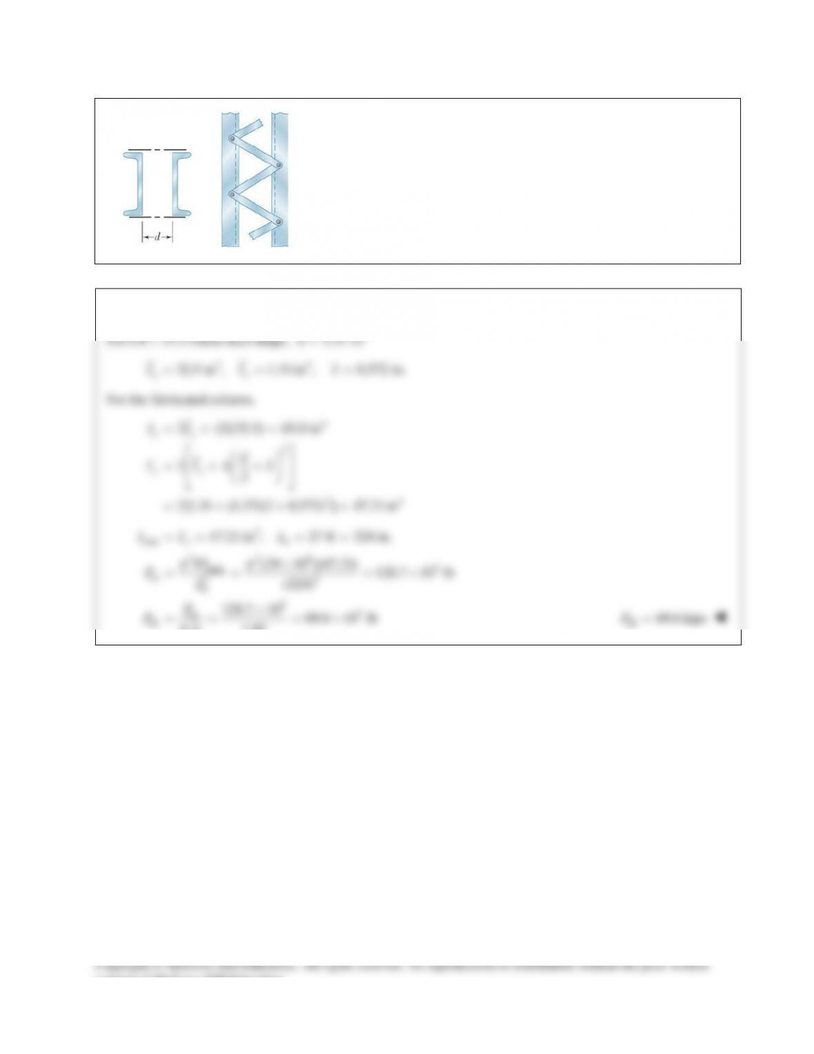
PROBLEM 16.16
A column of 3–m effective length is to be made by welding together two C130 × 13
rolled–steel channels. Using
200 GPa,E=
determine for each arrangement shown the
allowable centric load if a factor of safety of 2.4 is required.
SOLUTION
For channel C130 × 13:
2
1700 mm
A=
48.0 mm
f
b=
64
3.70 10 mm
x
I= ×
64
0.260 10 mm
y
I= ×
12.1 mmx=
Arrangement (a):
6 64
(2)(3.70 10 ) 7.40 10 mm
x
I= ×=×
6 2 62
2[0.260 10 (1700)(12.1) ] 1.0178 10 mm
y
I= ×+ = ×
6 64
min 1.0178 10 mm 1.0178 10 m
y
II −
==×=×
2 29 6 3
min
cr 22
(200 10 )(1.0178 10 ) 223 10 N 223 kN
(3.0)
e
EI
PL
ππ
−
××
= = =×=
cr
all
223
. . 2.4
P
PFS
= =
all
93.0 kNP=
Arrangement (b):
6 4 64
(2)(3.70 10 ) mm 7.40 10 mm
x
I=×=×
6 2 64
2[0.260 10 (1700)(48 12.1) ] 4.902 10 mm
y
I= ×+ − = ×
6 4 64
min
4.902 10 mm 4.902 10 m
y
II
−
==×=×
229 6 3
min
cr 22
(200 10 )(4.902 10 ) 1075 10 N 1075 kN
(3.0)
e
EI
PL
ππ
−
××
= = =×=
cr
all
1075
. . 2.4
P
PFS
= =
all
448 kNP=
consent of McGraw–Hill Education.
PROBLEM 16.17
Knowing that
5.2 kN,P=
determine the factor of safety for the structure
shown. Use
200E=
GPa and consider only buckling in the plane of the
structure.
SOLUTION
PROBLEM 16.18
Members AB and CD are 30–mm–diameter steel rods, and members BC
and AD are 22–mm–diameter steel rods. When the turnbuckle is
tightened, the diagonal member AC is put in tension. Knowing that a
factor of safety with respect to buckling of 2.75 is required, determine
the largest allowable tension in AC. Use
200E=
GPa and consider
only buckling in the plane of the structure.
SOLUTION
22
(3.5) (2.25) 4.1608 m
AC
L=+=
Joint C:
2.25
0: 0
4.1608
1.84926
Σ= − =
=
x BC AC
AC BC
FF T
TF
3.5
0: 0
4.1608
Σ= − =
y CD AC
FF T
1.1888
AC CD
TF=
Members BC and AD:
443 4 94
22 11.499 10 mm 11.499 10 m
4 2 42
BC
BC
d
I
ππ
−
= = =×=×
229 9 3
,cr 22
2.25 m
(200 10 )(11.499 10 ) 4.4836 10 N
(2.25)
BC
BC
BC BC
L
EI
FL
ππ
−
=
××
= = = ×
,cr 33
,all ,all
1.6304 10 N 3.02 10 N
..
BC
BC AC
F
FT
FS
==×=×
Members AB and CD:
443 4 94
30 39.761 10 mm 39.761 10 m
4 2 42
CD
CD d
I
ππ
−
= = =×=×
2
229 9 3
,cr 2
3.5 m
(200 10 )(39.761 10 ) 6.4069 10 N
(3.5)
CD
CD
CD
CD
L
EI
FL
ππ
−
=
××
= = = ×
, cr 33
,all ,all
2.3298 10 N 2.77 10 N
..
CD
CD AC
F
FT
FS
==×=×
Smaller value for
,allAC
T
governs.
,all 2.77 kN
AC
T=
consent of McGraw–Hill Education.
PROBLEM 16.19
A 1–in.–square aluminum strut is maintained in the position shown by a pin support at A
and by sets of rollers at B and C that prevent rotation of the strut in the plane of the
figure. Knowing that
3 ft,
AB
L=
4 ft,
BC
L=
and
1 ft,
CD
L=
determine the allowable
load P using a factor of safety with respect to buckling of 3.2. Consider only buckling
in the plane of the figure and use
6
10.4 10 psi.E= ×
SOLUTION
33 4
2
cr 2
2
cr min
all 2
max
11
(1)(1) 0.083333 in
12 12
()
.. ( . .)( )
e
e
I bh
EI
PL
PEI
PFS FS L
π
π
= = =
=
= =
Portion AB:
0.7 (0.7)(3) 2.1 ft
e AB
LL= = =
Portion BC:
0.5 (0.5)(4) 2.0 ft
e BC
LL= = =
Portion CD:
2 (2)(1) 2.0 ft
ee
LL= = =
max
( ) 2.1 ft 25.2 in.
e
L= =
26 3
all 2
(10.4 10 )(0.083333) 4.21 10 lb
(3.2)(25.2 )
P
π
×
= = ×
all 4.21 kipsP=
PROBLEM 16.20
A 1–in.–square aluminum strut is maintained in the position shown by a pin
support at A and by sets of rollers at B and C that prevent rotation of the strut in
the plane of the figure. Knowing that
3
AB
L=
ft, determine (a) the largest
values of
BC
L
and
CD
L
that can be used if the allowable load P is to be as large
as possible, (b) the magnitude of the corresponding allowable load. Consider
only buckling in the plane of the figure and use
6
10.4 10
E= ×
psi.
SOLUTION
33 4
11
(1)(1) 0.083333 in
12 12
I bh
= = =
(a) Equivalent lengths:
AB:
0.7 2.1ft 25.2 in.
e AB
LL= = =
BC:
0.5
e BC
LL=
2.1
0.5
BC
L=
4.20 ft=
BC
L
CD:
2
e CD
LL=
2.1
2
CD
L=
1.050 ft
=
CD
L
(b)
22 6
cr
all 22
3
(10.4 10 )(0.083333)
.. ( . .) (3.2)(25.2)
4.21 10 lb
e
PEI
PFS FS L
ππ
×
= = =
= ×
all
4.21kipsP=
consent of McGraw–Hill Education.
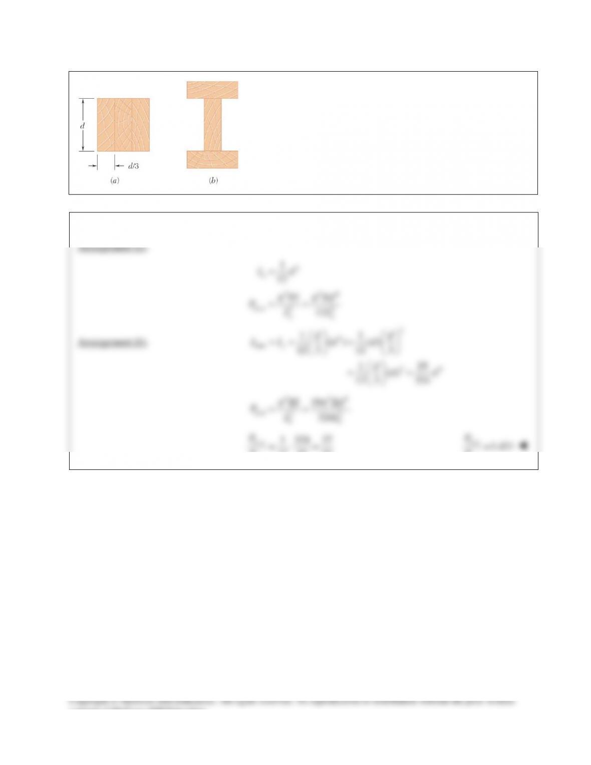
PROBLEM 16.12
A column of effective length L can be made by gluing together
identical planks in either of the arrangements shown. Determine the
ratio of the critical load using the arrangement a to the critical load
using the arrangement b.
SOLUTION
PROBLEM 16.13
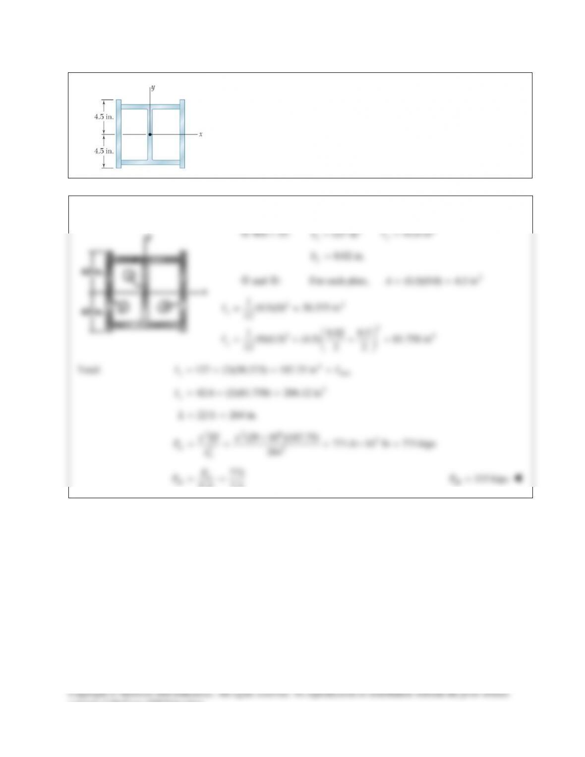
A compression member of 7–m effective length is made by welding
together two
L152 102 12.7
××
angles as shown. Using
200 GPa,E=
determine the allowable centric load for the
member if a factor of safety of 2.2 is required.
SOLUTION
Angle L152 × 102 × 12.7:
2
64 64
3060 mm
7.20 10 mm 2.64 10 mm
50.3 mm 25.3 mm
xy
A
II
yx
=
=×=×
= =
Two angles:
6 64
(2)(7.20 10 ) 14.40 10 mm
x
I= ×= ×
6 2 64
2[(2.64 10 ) (3060)(25.3) ] 9.197 10 mm
y
I= ×+ = ×
6 4 64
min 9.197 10 mm 9.197 10 m
y
II −
==×=×
22 9 6 3
cr 22
(200 10 )(9.197 10 ) 370.5 10 N 370.5 kN
(7.0)
e
EI
PL
ππ
−
××
== =×=
cr
all
370.5
. . 2.2
P
PFS
= =
all 168.4 kNP=
consent of McGraw–Hill Education.
PROBLEM 16.14
A single compression member of 27–ft effective length is obtained by
connecting two C8 × 11.5 steel channels with lacing bars as shown.
Knowing that the factor of safety is 1.85, determine the allowable
centric load for the member. Use
6
29 10 psiE= ×
and
4.0 in.d=
SOLUTION
2
PROBLEM 16.15
A column of 22–ft effective length is to be made by welding two
9 0.5-in.×
plates to a W8 × 35 as shown. Determine the allowable
centric load if a factor of safety 2.3 is required. Use
6
29 10 psi.×
SOLUTION
4
4
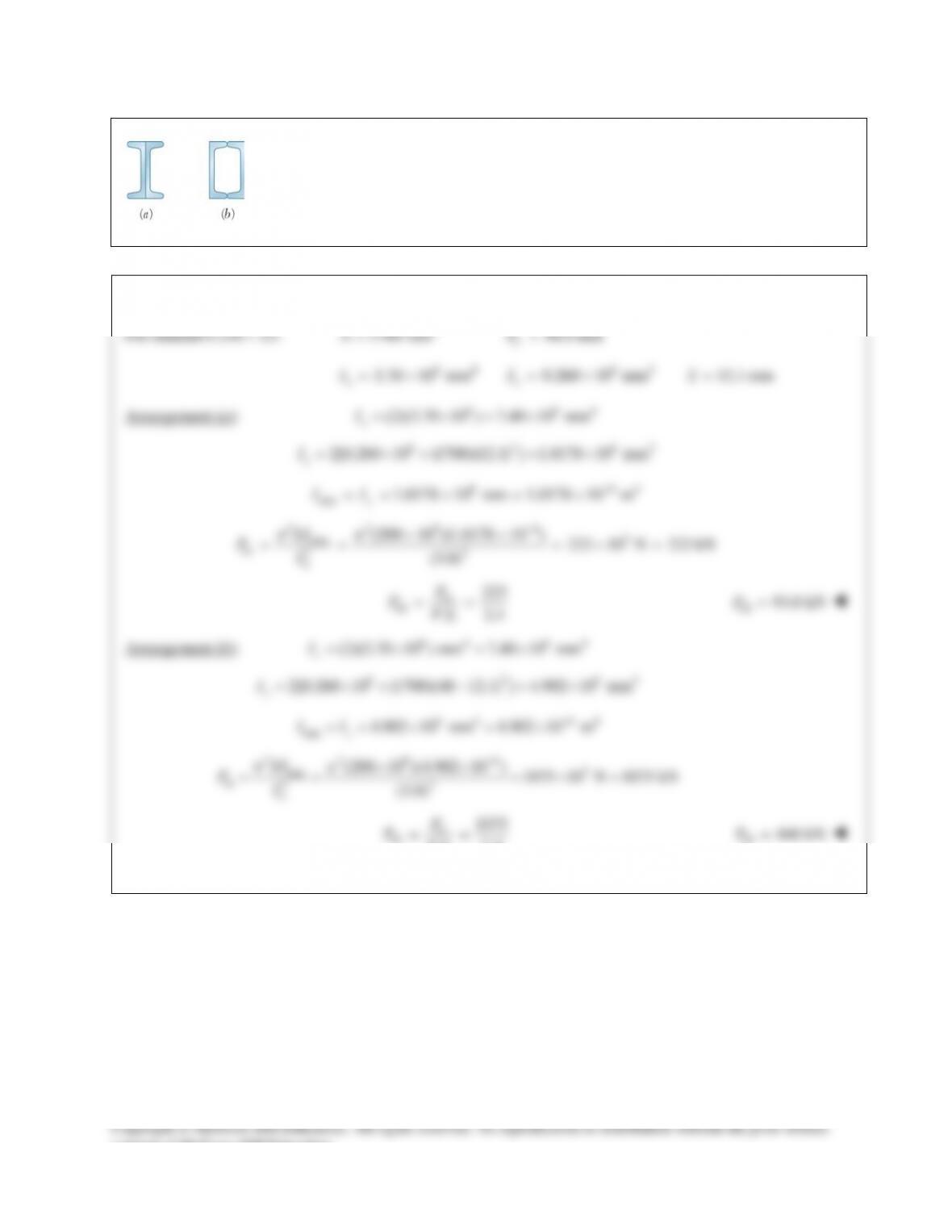
PROBLEM 16.16
A column of 3–m effective length is to be made by welding together two C130 × 13
rolled–steel channels. Using
200 GPa,E=
determine for each arrangement shown the
allowable centric load if a factor of safety of 2.4 is required.
SOLUTION
For channel C130 × 13:
2
1700 mm
A=
48.0 mm
f
b=
64
3.70 10 mm
x
I= ×
64
0.260 10 mm
y
I= ×
12.1 mmx=
Arrangement (a):
6 64
(2)(3.70 10 ) 7.40 10 mm
x
I= ×=×
6 2 62
2[0.260 10 (1700)(12.1) ] 1.0178 10 mm
y
I= ×+ = ×
6 64
min 1.0178 10 mm 1.0178 10 m
y
II −
==×=×
2 29 6 3
min
cr 22
(200 10 )(1.0178 10 ) 223 10 N 223 kN
(3.0)
e
EI
PL
ππ
−
××
= = =×=
cr
all
223
. . 2.4
P
PFS
= =
all
93.0 kNP=
Arrangement (b):
6 4 64
(2)(3.70 10 ) mm 7.40 10 mm
x
I=×=×
6 2 64
2[0.260 10 (1700)(48 12.1) ] 4.902 10 mm
y
I= ×+ − = ×
6 4 64
min
4.902 10 mm 4.902 10 m
y
II
−
==×=×
229 6 3
min
cr 22
(200 10 )(4.902 10 ) 1075 10 N 1075 kN
(3.0)
e
EI
PL
ππ
−
××
= = =×=
cr
all
1075
. . 2.4
P
PFS
= =
all
448 kNP=
consent of McGraw–Hill Education.
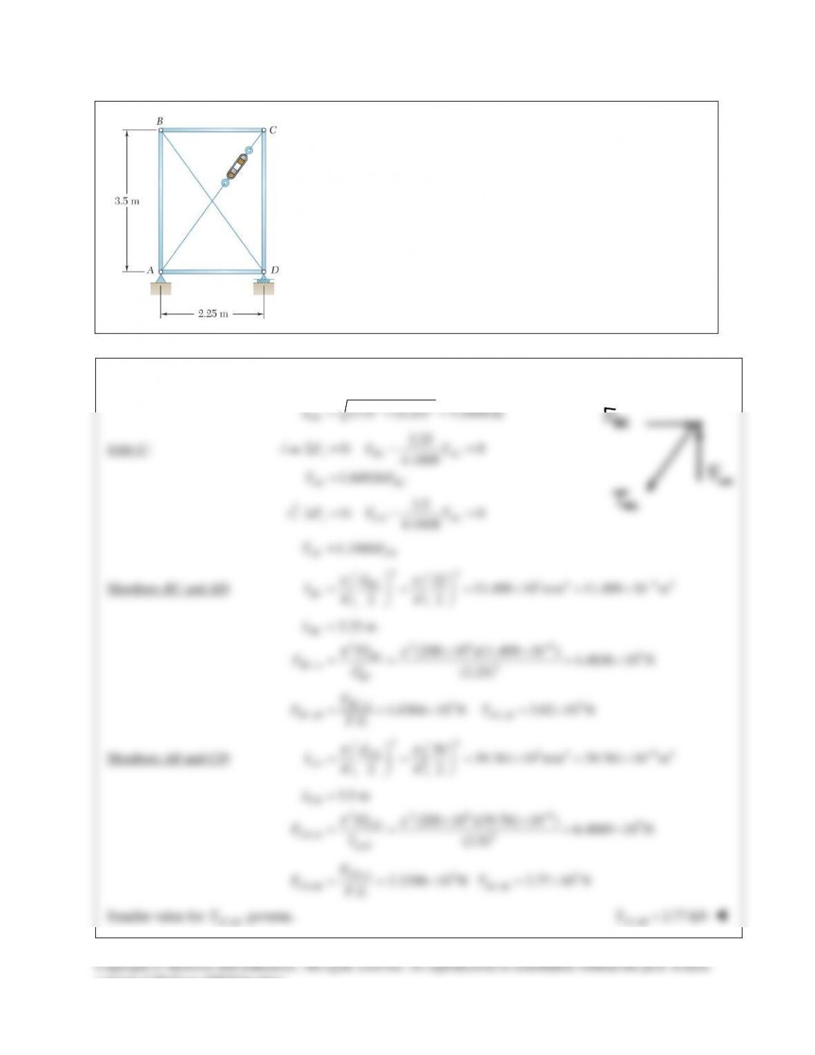
PROBLEM 16.17
Knowing that
5.2 kN,P=
determine the factor of safety for the structure
shown. Use
200E=
GPa and consider only buckling in the plane of the
structure.
SOLUTION
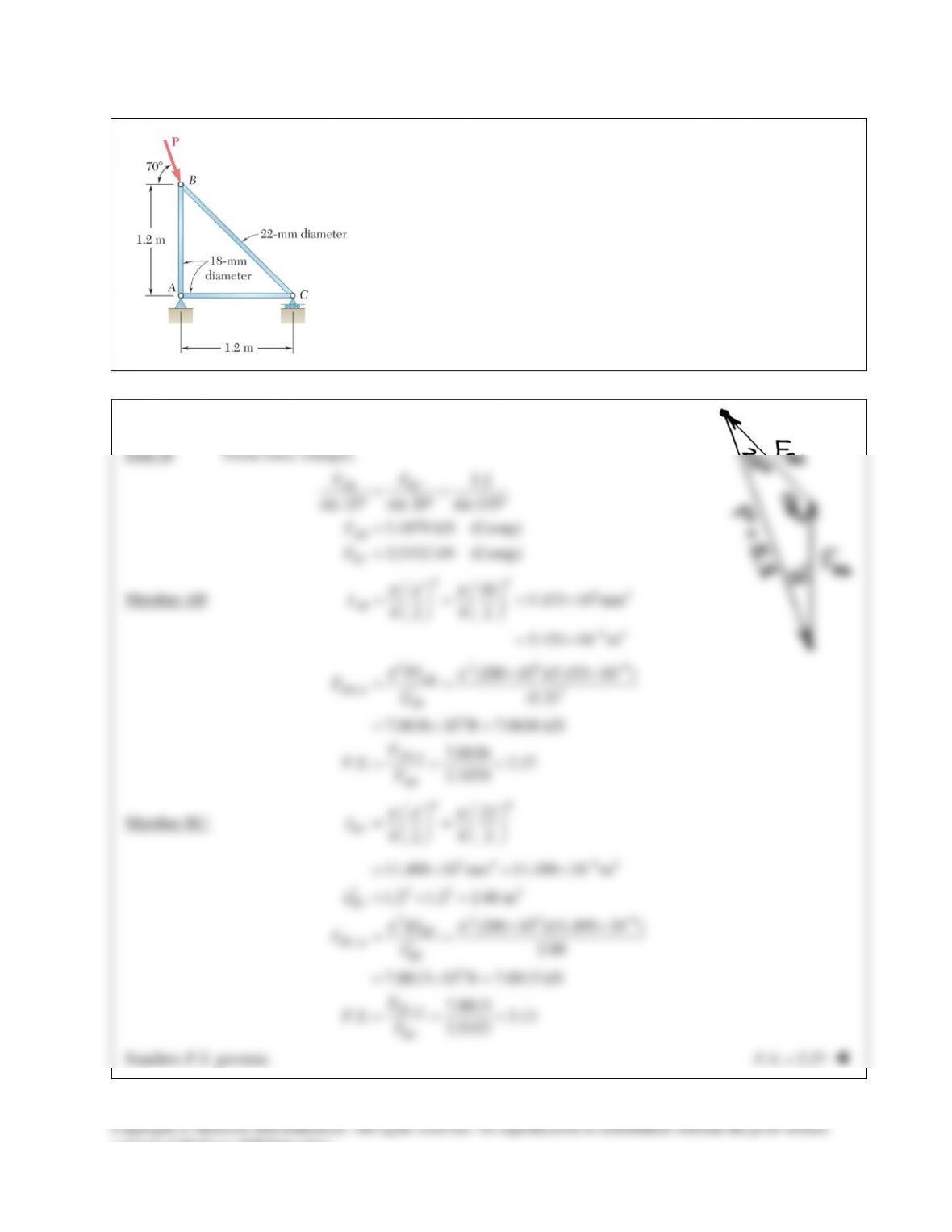
PROBLEM 16.18
Members AB and CD are 30–mm–diameter steel rods, and members BC
and AD are 22–mm–diameter steel rods. When the turnbuckle is
tightened, the diagonal member AC is put in tension. Knowing that a
factor of safety with respect to buckling of 2.75 is required, determine
the largest allowable tension in AC. Use
200E=
GPa and consider
only buckling in the plane of the structure.
SOLUTION
22
(3.5) (2.25) 4.1608 m
AC
L=+=
Joint C:
2.25
0: 0
4.1608
1.84926
Σ= − =
=
x BC AC
AC BC
FF T
TF
3.5
0: 0
4.1608
Σ= − =
y CD AC
FF T
1.1888
AC CD
TF=
Members BC and AD:
443 4 94
22 11.499 10 mm 11.499 10 m
4 2 42
BC
BC
d
I
ππ
−
= = =×=×
229 9 3
,cr 22
2.25 m
(200 10 )(11.499 10 ) 4.4836 10 N
(2.25)
BC
BC
BC BC
L
EI
FL
ππ
−
=
××
= = = ×
,cr 33
,all ,all
1.6304 10 N 3.02 10 N
..
BC
BC AC
F
FT
FS
==×=×
Members AB and CD:
443 4 94
30 39.761 10 mm 39.761 10 m
4 2 42
CD
CD d
I
ππ
−
= = =×=×
2
229 9 3
,cr 2
3.5 m
(200 10 )(39.761 10 ) 6.4069 10 N
(3.5)
CD
CD
CD
CD
L
EI
FL
ππ
−
=
××
= = = ×
, cr 33
,all ,all
2.3298 10 N 2.77 10 N
..
CD
CD AC
F
FT
FS
==×=×
Smaller value for
,allAC
T
governs.
,all 2.77 kN
AC
T=
consent of McGraw–Hill Education.
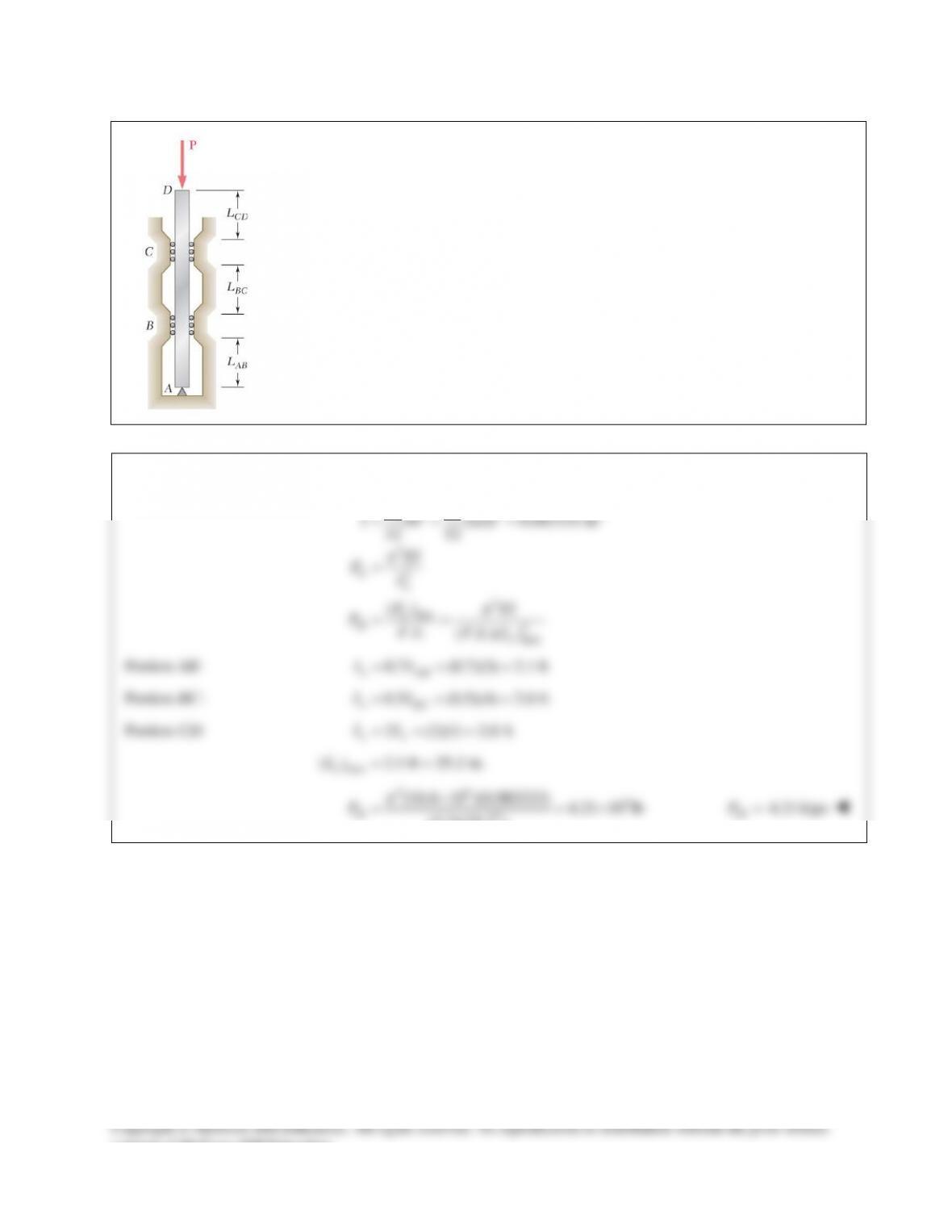
PROBLEM 16.19
A 1–in.–square aluminum strut is maintained in the position shown by a pin support at A
and by sets of rollers at B and C that prevent rotation of the strut in the plane of the
figure. Knowing that
3 ft,
AB
L=
4 ft,
BC
L=
and
1 ft,
CD
L=
determine the allowable
load P using a factor of safety with respect to buckling of 3.2. Consider only buckling
in the plane of the figure and use
6
10.4 10 psi.E= ×
SOLUTION
33 4
2
cr 2
2
cr min
all 2
max
11
(1)(1) 0.083333 in
12 12
()
.. ( . .)( )
e
e
I bh
EI
PL
PEI
PFS FS L
π
π
= = =
=
= =
Portion AB:
0.7 (0.7)(3) 2.1 ft
e AB
LL= = =
Portion BC:
0.5 (0.5)(4) 2.0 ft
e BC
LL= = =
Portion CD:
2 (2)(1) 2.0 ft
ee
LL= = =
max
( ) 2.1 ft 25.2 in.
e
L= =
26 3
all 2
(10.4 10 )(0.083333) 4.21 10 lb
(3.2)(25.2 )
P
π
×
= = ×
all 4.21 kipsP=
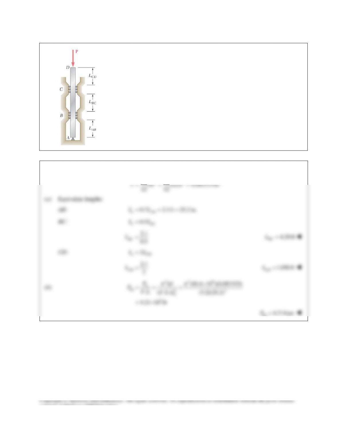
PROBLEM 16.20
A 1–in.–square aluminum strut is maintained in the position shown by a pin
support at A and by sets of rollers at B and C that prevent rotation of the strut in
the plane of the figure. Knowing that
3
AB
L=
ft, determine (a) the largest
values of
BC
L
and
CD
L
that can be used if the allowable load P is to be as large
as possible, (b) the magnitude of the corresponding allowable load. Consider
only buckling in the plane of the figure and use
6
10.4 10
E= ×
psi.
SOLUTION
33 4
11
(1)(1) 0.083333 in
12 12
I bh
= = =
(a) Equivalent lengths:
AB:
0.7 2.1ft 25.2 in.
e AB
LL= = =
BC:
0.5
e BC
LL=
2.1
0.5
BC
L=
4.20 ft=
BC
L
CD:
2
e CD
LL=
2.1
2
CD
L=
1.050 ft
=
CD
L
(b)
22 6
cr
all 22
3
(10.4 10 )(0.083333)
.. ( . .) (3.2)(25.2)
4.21 10 lb
e
PEI
PFS FS L
ππ
×
= = =
= ×
all
4.21kipsP=
consent of McGraw–Hill Education.