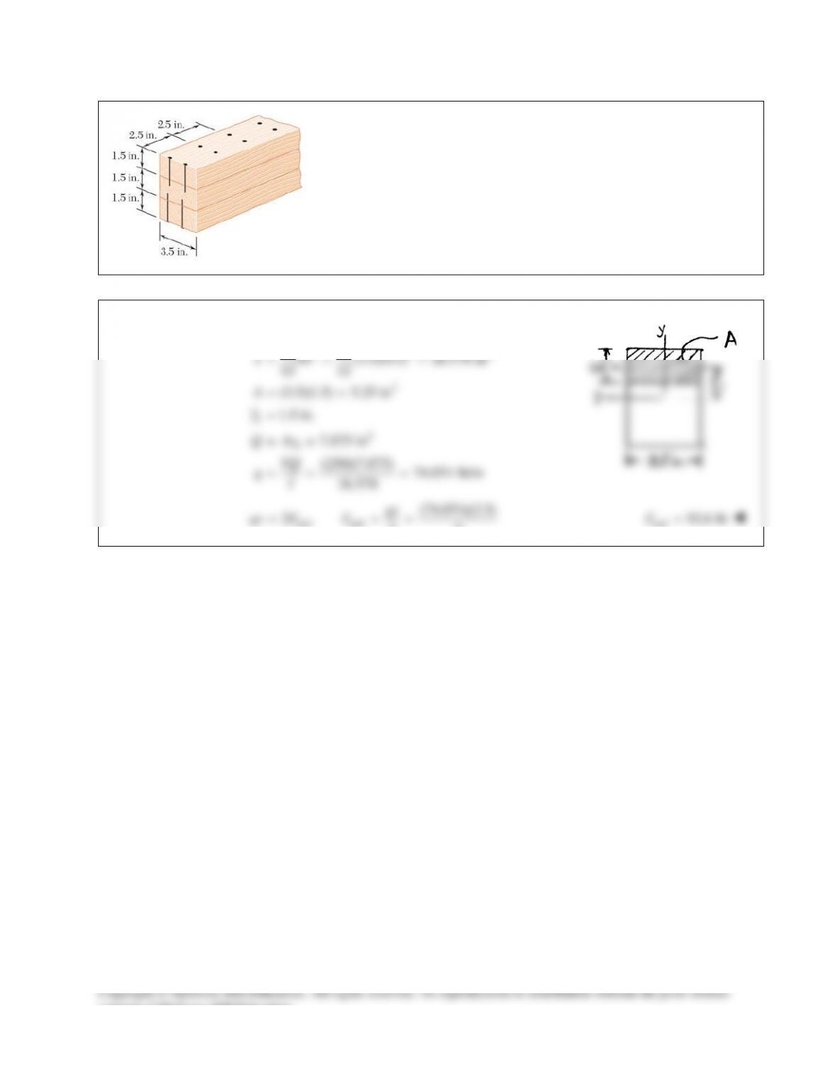
PROBLEM 13.2
Three boards, each 2 in. thick, are nailed together to form a beam
that is subjected to a vertical shear. Knowing that the allowable
shearing force in each nail is 150 lb, determine the allowable shear
if the spacing s between the nails is 3 in.
SOLUTION
32
1
3 24
33 4
2
4
31
4
123
1
12
1(6)(2) (6)(2)(3) 112 in
12
11
(2)(4) 10.6667 in
12 12
112 in
234.67 in
I bh Ad
I bh
II
III I
= +
=+=
= = =
= =
=++=
3
11
nail
(6)(2)(3) 36 in
(1)
(2)
Q Ay
qs F
VQ
qI
= = =
=
=
Dividing Eq. (2) by Eq. (1),
nail
1VQ
s FI
=
nail
(150)(234.67)
(36)(3)
FI
VQs
= =
326 lbV=
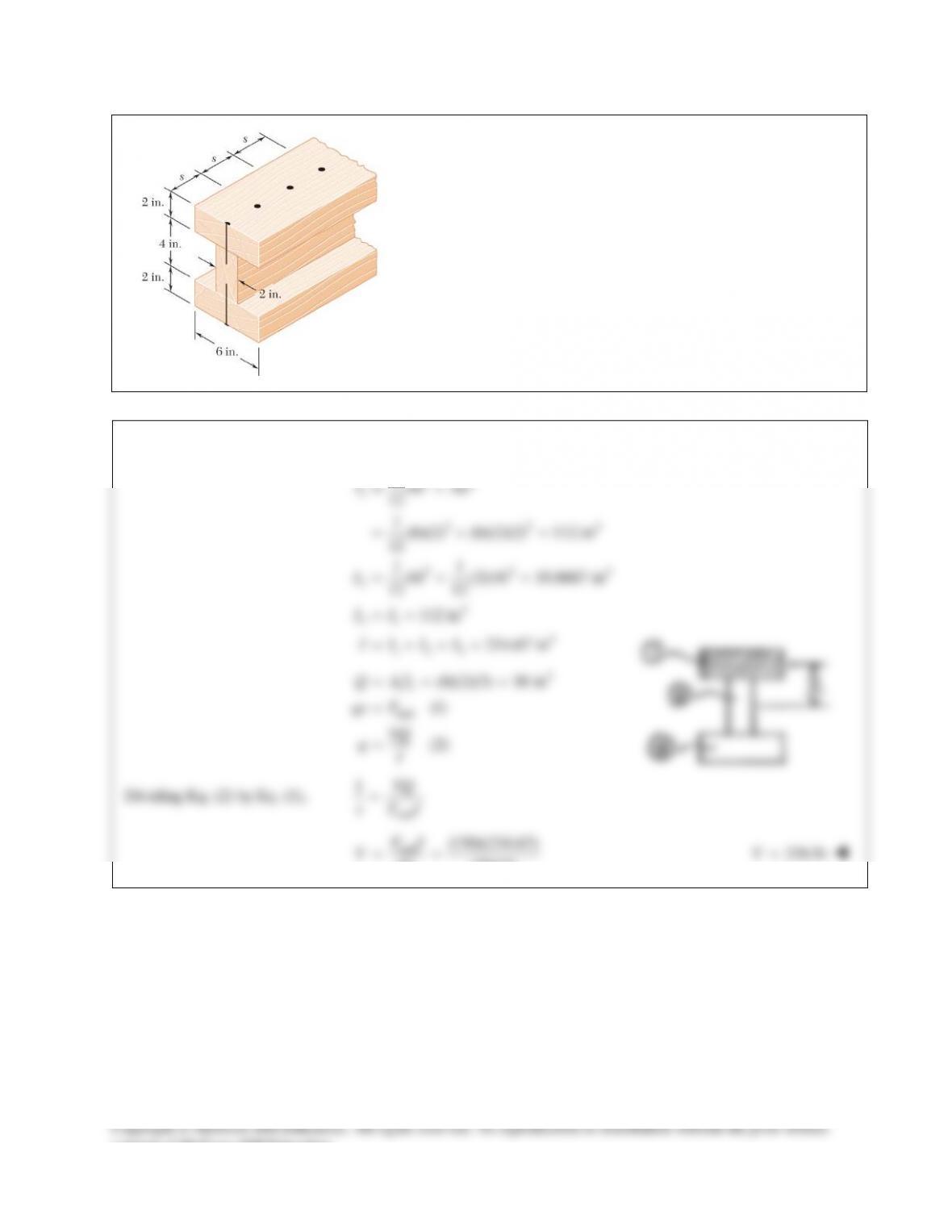
PROBLEM 13.3
Three boards are nailed together to form a beam shown, which is
subjected to a vertical shear. Knowing that the spacing between the
nails is
75mms=
and that the allowable shearing force in each nail is
400 N, determine the allowable shear when
120 mm.w=
SOLUTION
PROBLEM 13.4
Solve Prob. 13.3, assuming that the width of the top and bottom boards
is changed to
100 mmw=
.
PROBLEM 13.3 Three boards are nailed together to form a beam
shown, which is subjected to a vertical shear. Knowing that the spacing
between the nails is
75mms=
and that the allowable shearing force
in each nail is 400 N, determine the allowable shear when
120 mm.w=
PROBLEM 13.5
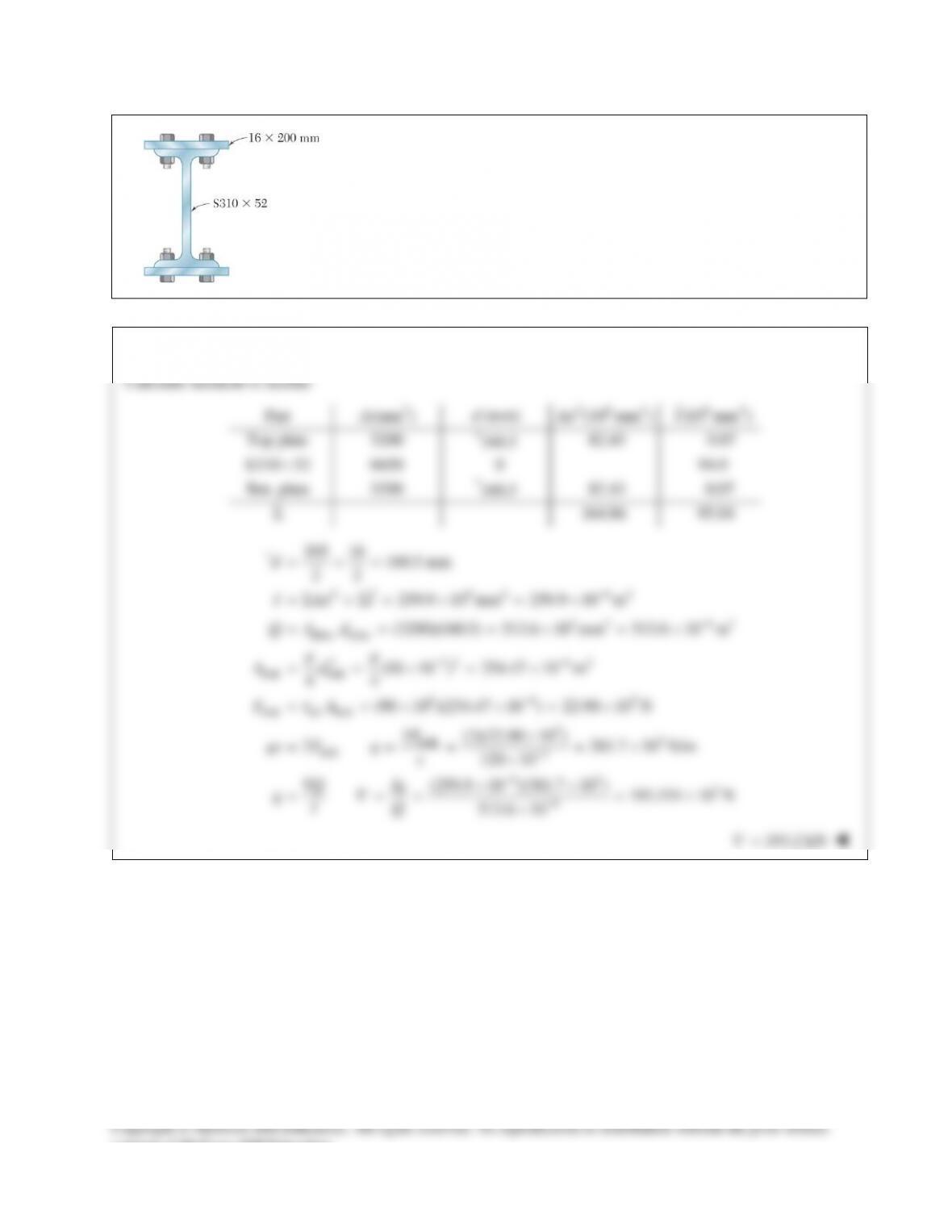
The American Standard rolled–steel beam shown has been reinforced by
attaching to it two
16 200-mm×
plates, using 18–mm–diameter bolts
spaced longitudinally every 120 mm. Knowing that the average allowable
shearing stress in the bolts is 90 MPa, determine the largest permissible
vertical shearing force.
SOLUTION
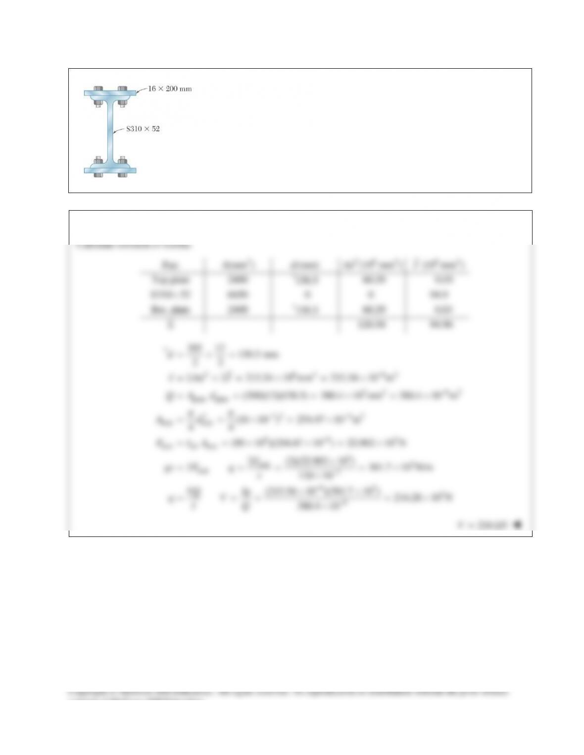
PROBLEM 13.6
Solve Prob. 13.5, assuming that the reinforcing plates are only 12 mm thick.
PROBLEM 13.5 The American Standard rolled–steel beam shown has been
reinforced by attaching to it two
16 200-mm×
plates, using 18–mm–diameter
bolts spaced longitudinally every 120 mm. Knowing that the average
allowable shearing stress in the bolts is 90 MPa, determine the largest
permissible vertical shearing force.
SOLUTION
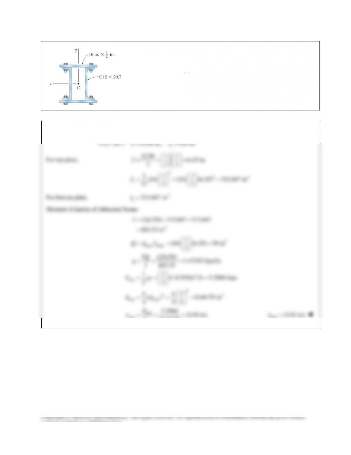
PROBLEM 13.7
The beam shown is fabricated by connecting two channel shapes and two
plates, using bolts of
3
4
-in.
diameter spaced longitudinally every 7.5 in.
Determine the average shearing stress in the bolts caused by a shearing
force of 25 kips parallel to the y axis.
SOLUTION
4
C12 20.7: 12.00 in., 129 in
x
dI
×= =
For top plate,
324
12.00 1 1 6.25 in.
2 22
11 1
(16) (16) (6.25) 312.667 in
12 2 2
t
y
I
=+=
=+=
For bottom plate,
4
312.667 in
b
I=
Moment of inertia of fabricated beam:
4
3
plate plate
bolt
2
22
bolt bolt
(2)(129) 312.667 312.667
883.33 in
1
(16) (6.25) 50 in
2
(25)(50) 1.41510 kips/in.
883.33
11
(1.41510)(7.5) 5.3066 kips
22
3
( ) 0.44179 in
4 44
I
QA y
VQ
qI
F qs
Ad
pp
t
=++
=
= = =
= = =
= = =
= = =
bolt
bolt bolt
5.3066 12.01 ksi
0.44179
F
A
= = =
bolt
12.01 ksi
t
=
consent of McGraw–Hill Education.
PROBLEM 13.8
A column is fabricated by connecting the rolled–steel members shown by
bolts of
3
4
-in.
diameter spaced longitudinally every 5 in. Determine the
average shearing stress in the bolts caused by a shearing force of 30 kips
parallel to the y axis.
SOLUTION
PROBLEM 13.9
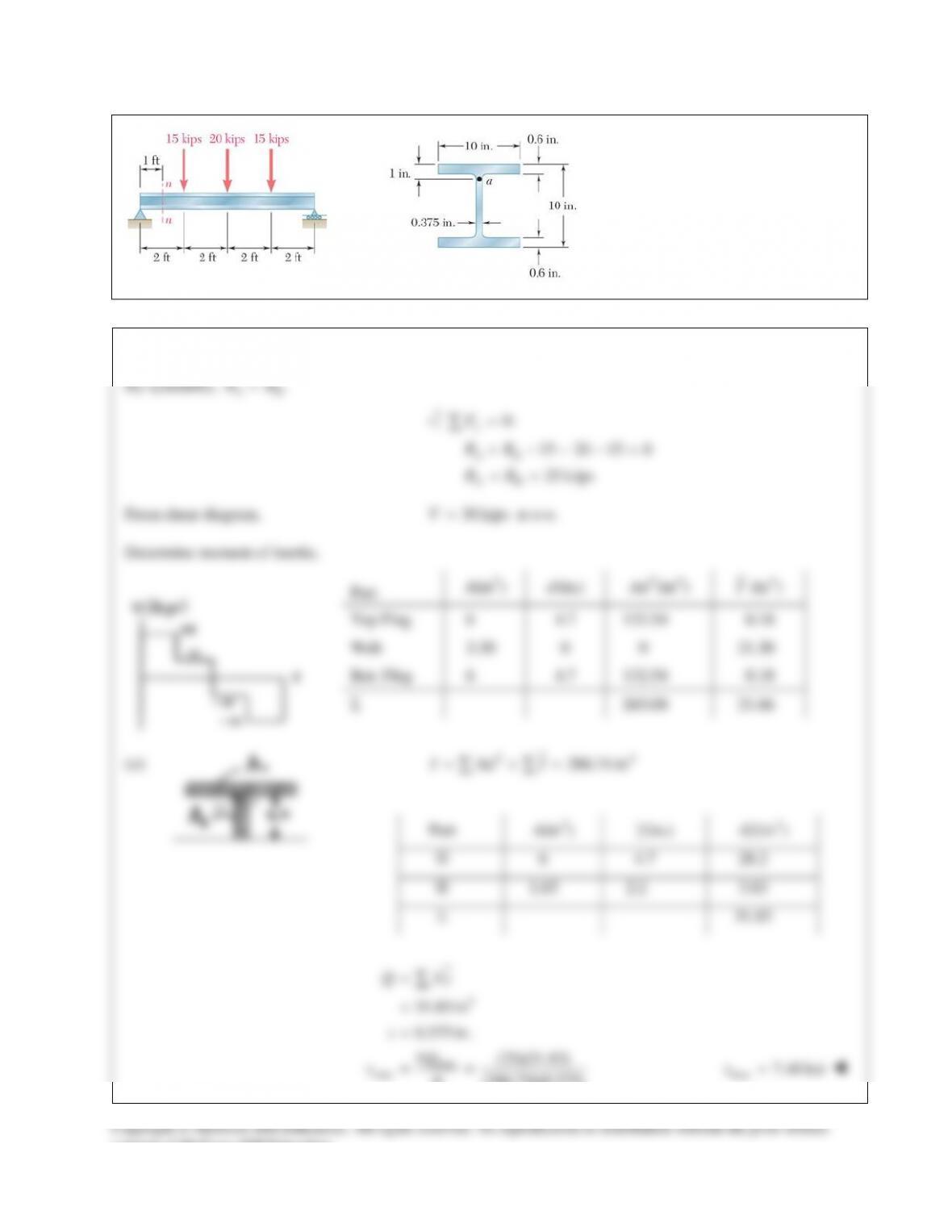
For the beam and loading shown,
consider section n-n and determine
(a) the largest shearing stress in that
section, (b) the shearing stress at
point a.
SOLUTION
By symmetry,
.
AB
RR
=
0:
15 20 15 0
25 kips
y
AB
AB
F
RR
RR
=
+ −−−=
= =
∑
From shear diagram,
30 kipsV=
at n-n.
Determine moment of inertia.
(a)
24
286.74 inI Ad I= +=
∑∑
Part
2
(in )
A
(in.)y
3
(in )Ay
6
4.7
28.2
1.65
2.2
3.63
Σ
31.83
3
max
max
31.83 in
0.375 in.
(25)(31.83)
(286.74)(0.375)
Q Ay
t
VQ
It
t
=
=
=
= =
∑
max 7.40 ksi
t
=
Part
2
(in )
A
(in.)d
24
(in )Ad
4
(in )I
Top Flng 6 4.7 132.54 0.18
Web 3.30 0 0 21.30
Bot. Flng 6 4.7 132.54 0.18
Σ 265.08 21.66
consent of McGraw–Hill Education.
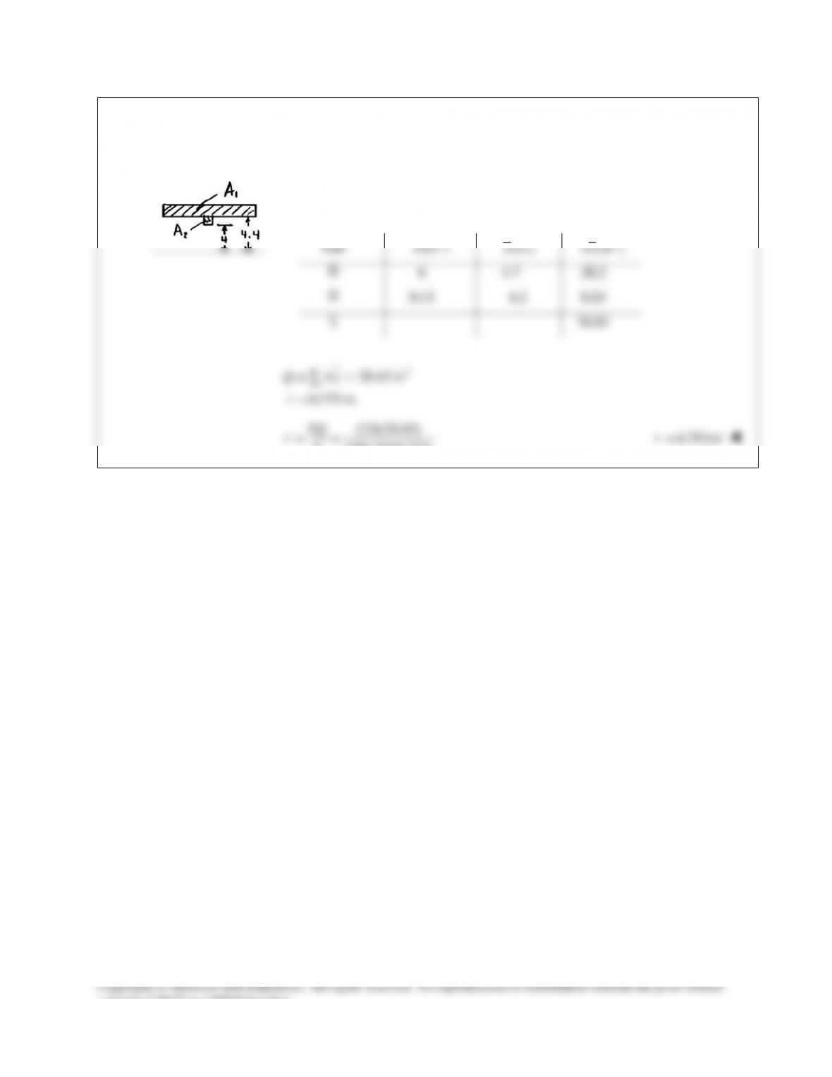
PROBLEM 13.9 (Continued)
(b)
2
PROBLEM 13.2
Three boards, each 2 in. thick, are nailed together to form a beam
that is subjected to a vertical shear. Knowing that the allowable
shearing force in each nail is 150 lb, determine the allowable shear
if the spacing s between the nails is 3 in.
SOLUTION
32
1
3 24
33 4
2
4
31
4
123
1
12
1(6)(2) (6)(2)(3) 112 in
12
11
(2)(4) 10.6667 in
12 12
112 in
234.67 in
I bh Ad
I bh
II
III I
= +
=+=
= = =
= =
=++=
3
11
nail
(6)(2)(3) 36 in
(1)
(2)
Q Ay
qs F
VQ
qI
= = =
=
=
Dividing Eq. (2) by Eq. (1),
nail
1VQ
s FI
=
nail
(150)(234.67)
(36)(3)
FI
VQs
= =
326 lbV=
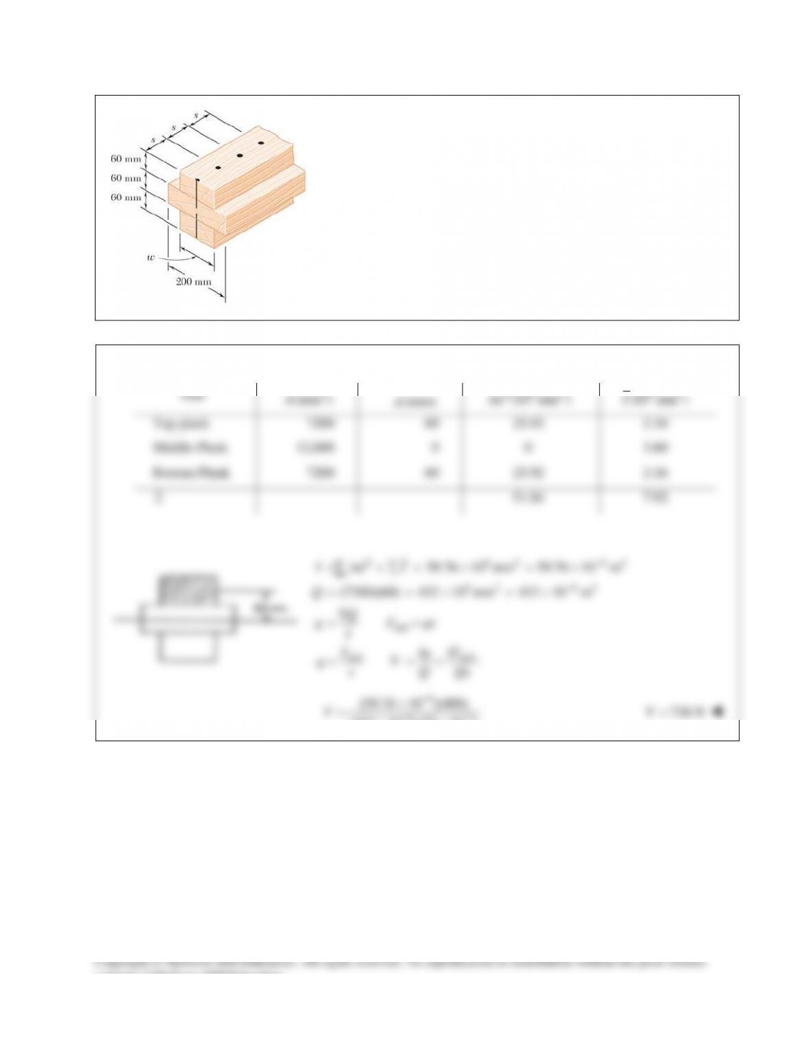
PROBLEM 13.3
Three boards are nailed together to form a beam shown, which is
subjected to a vertical shear. Knowing that the spacing between the
nails is
75mms=
and that the allowable shearing force in each nail is
400 N, determine the allowable shear when
120 mm.w=
SOLUTION
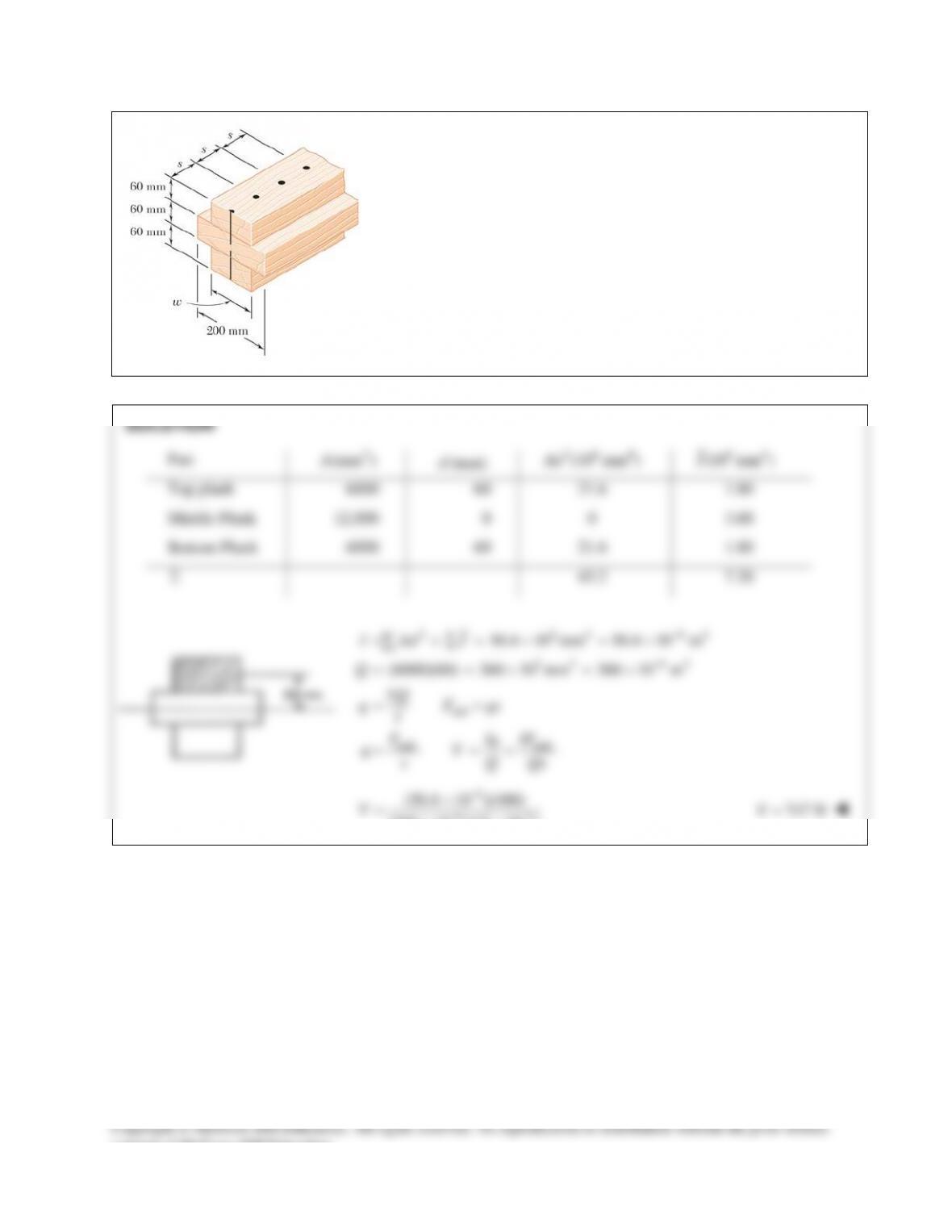
PROBLEM 13.4
Solve Prob. 13.3, assuming that the width of the top and bottom boards
is changed to
100 mmw=
.
PROBLEM 13.3 Three boards are nailed together to form a beam
shown, which is subjected to a vertical shear. Knowing that the spacing
between the nails is
75mms=
and that the allowable shearing force
in each nail is 400 N, determine the allowable shear when
120 mm.w=
PROBLEM 13.5
The American Standard rolled–steel beam shown has been reinforced by
attaching to it two
16 200-mm×
plates, using 18–mm–diameter bolts
spaced longitudinally every 120 mm. Knowing that the average allowable
shearing stress in the bolts is 90 MPa, determine the largest permissible
vertical shearing force.
SOLUTION
PROBLEM 13.6
Solve Prob. 13.5, assuming that the reinforcing plates are only 12 mm thick.
PROBLEM 13.5 The American Standard rolled–steel beam shown has been
reinforced by attaching to it two
16 200-mm×
plates, using 18–mm–diameter
bolts spaced longitudinally every 120 mm. Knowing that the average
allowable shearing stress in the bolts is 90 MPa, determine the largest
permissible vertical shearing force.
SOLUTION
PROBLEM 13.7
The beam shown is fabricated by connecting two channel shapes and two
plates, using bolts of
3
4
-in.
diameter spaced longitudinally every 7.5 in.
Determine the average shearing stress in the bolts caused by a shearing
force of 25 kips parallel to the y axis.
SOLUTION
4
C12 20.7: 12.00 in., 129 in
x
dI
×= =
For top plate,
324
12.00 1 1 6.25 in.
2 22
11 1
(16) (16) (6.25) 312.667 in
12 2 2
t
y
I
=+=
=+=
For bottom plate,
4
312.667 in
b
I=
Moment of inertia of fabricated beam:
4
3
plate plate
bolt
2
22
bolt bolt
(2)(129) 312.667 312.667
883.33 in
1
(16) (6.25) 50 in
2
(25)(50) 1.41510 kips/in.
883.33
11
(1.41510)(7.5) 5.3066 kips
22
3
( ) 0.44179 in
4 44
I
QA y
VQ
qI
F qs
Ad
pp
t
=++
=
= = =
= = =
= = =
= = =
bolt
bolt bolt
5.3066 12.01 ksi
0.44179
F
A
= = =
bolt
12.01 ksi
t
=
consent of McGraw–Hill Education.
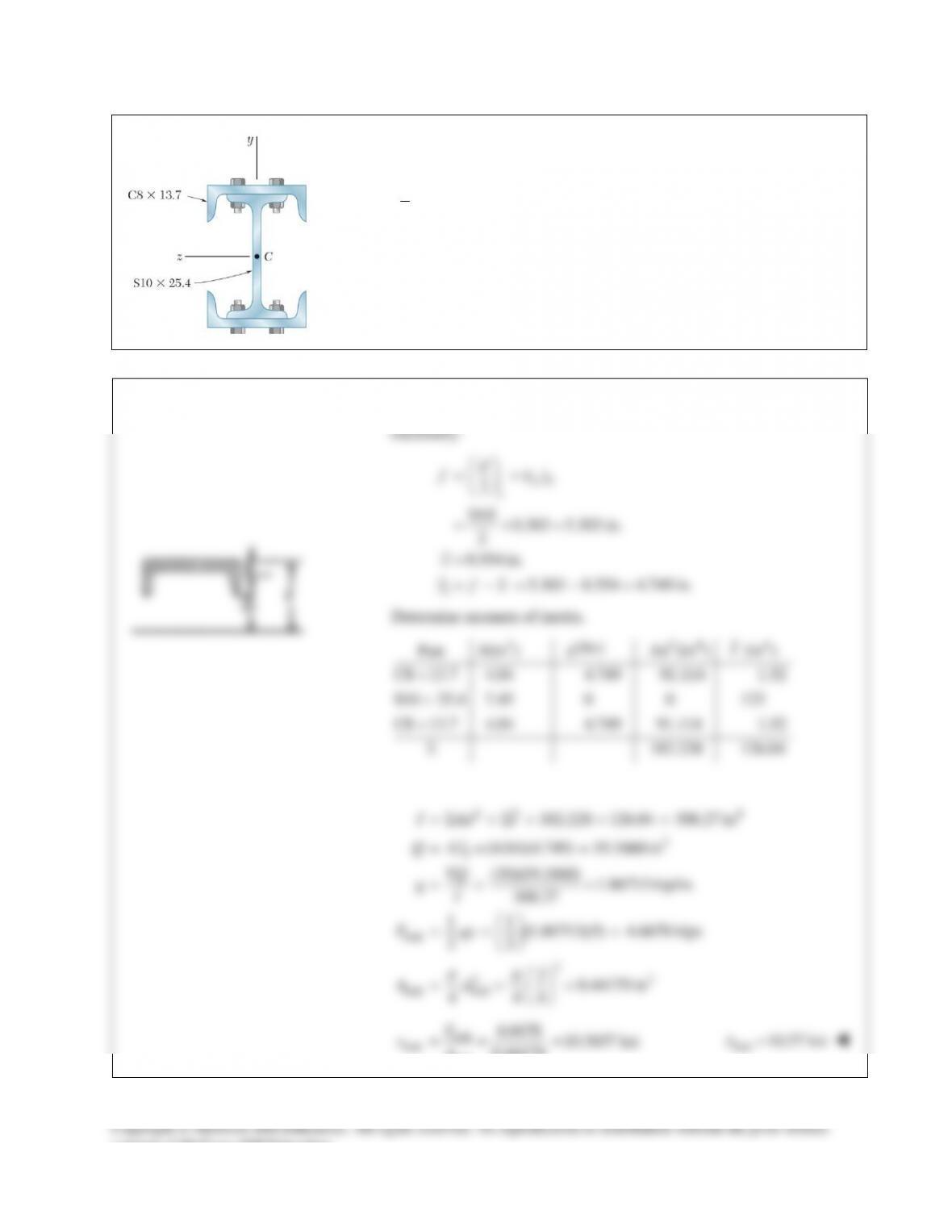
PROBLEM 13.8
A column is fabricated by connecting the rolled–steel members shown by
bolts of
3
4
-in.
diameter spaced longitudinally every 5 in. Determine the
average shearing stress in the bolts caused by a shearing force of 30 kips
parallel to the y axis.
SOLUTION
PROBLEM 13.9
For the beam and loading shown,
consider section n-n and determine
(a) the largest shearing stress in that
section, (b) the shearing stress at
point a.
SOLUTION
By symmetry,
.
AB
RR
=
0:
15 20 15 0
25 kips
y
AB
AB
F
RR
RR
=
+ −−−=
= =
∑
From shear diagram,
30 kipsV=
at n-n.
Determine moment of inertia.
(a)
24
286.74 inI Ad I= +=
∑∑
Part
2
(in )
A
(in.)y
3
(in )Ay
6
4.7
28.2
1.65
2.2
3.63
Σ
31.83
3
max
max
31.83 in
0.375 in.
(25)(31.83)
(286.74)(0.375)
Q Ay
t
VQ
It
t
=
=
=
= =
∑
max 7.40 ksi
t
=
Part
2
(in )
A
(in.)d
24
(in )Ad
4
(in )I
Top Flng 6 4.7 132.54 0.18
Web 3.30 0 0 21.30
Bot. Flng 6 4.7 132.54 0.18
Σ 265.08 21.66
consent of McGraw–Hill Education.
PROBLEM 13.9 (Continued)
(b)
2