consent of McGraw–Hill Education.
PROBLEM 10.39
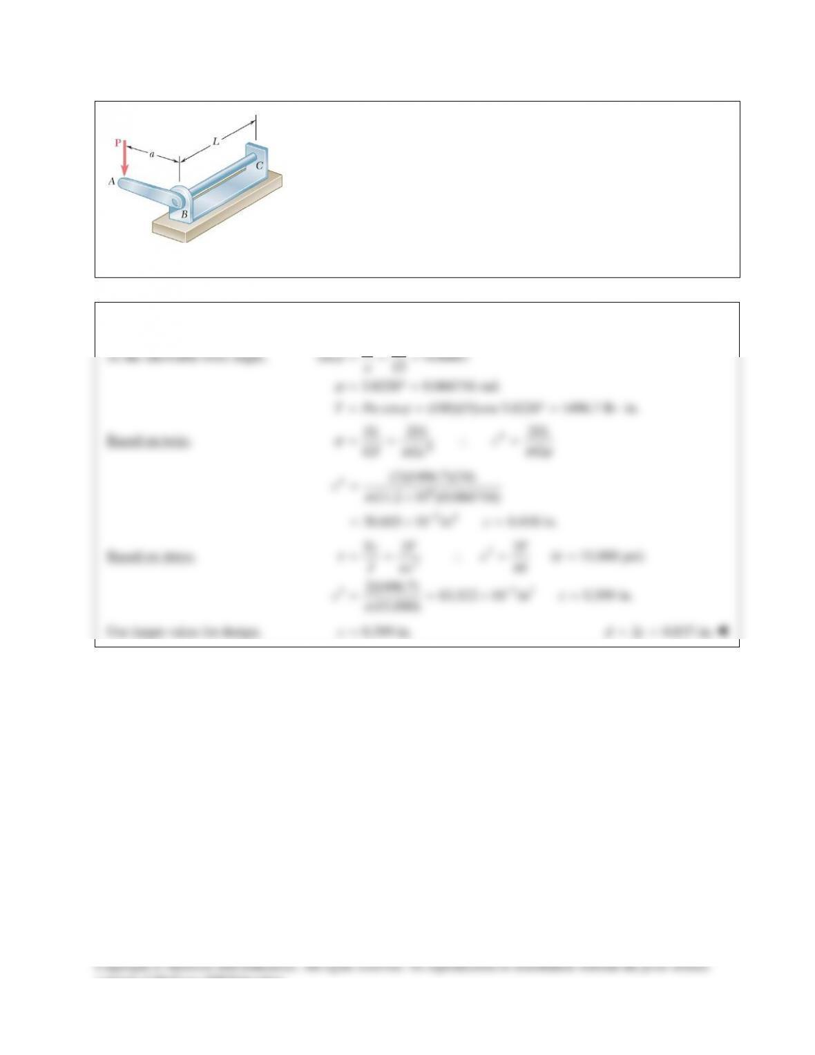
The solid cylindrical rod BC of length L = 24 in. is attached to the rigid
lever AB of length a = 15 in. and to the support at C. Design specifications
require that the displacement of A not exceed 1 in. when a 100–lb force P is
applied at A. For the material indicated, determine the required diameter of
the rod.
Steel:
τ
all = 15 ksi, G = 11.2 × 10⁶ psi.
SOLUTION
At the allowable twist angle,
1
sin 0.06667
15
3.8226 0.066716 rad.
cos (100)(15)cos 3.8226 1496.7 lb in.
ϕ
ϕ
ϕ
∆
= = =
= °=
= = °= ⋅
a
T Pa
Based on twist.
4
4
22
ϕπϕ
π
== ∴=
TL TL TL
c
GJ G
Gc
46
34
(2)(1496.7)(24)
(11.2 10 )(0.066716)
30.603 10 in 0.418 in.
c
c
π
−
=×
=×=
Based on stress.
3
3
3 33
22
( 15,000 psi)
2(1496.7) 63.522 10 in 0.399 in.
(15,000)
ττ
πτ
π
π
−
== ∴= =
==×=
Tc T T
c
Jc
cc
Use larger value for design.
0.399 in.
=c
2 0.837 in.
dc= =
consent of McGraw–Hill Education.
PROBLEM 10.40
The solid cylindrical rod BC of length L = 24 in. is attached to the rigid
lever AB of length a = 15 in. and to the support at C. Design specifications
require that the displacement of A not exceed 1 in. when a 100–lb force P is
applied at A. For the material indicated, determine the required diameter of
the rod.
Aluminum:
τ
all = 10 ksi, G = 3.9 × 10⁶ psi.
SOLUTION
At the allowable twist angle,
1
sin 0.06667
15
3.8226 0.066716 rad
cos (100)(15)cos3.8226 1496.7 lb in.
a
T Pa
ϕ
ϕ
ϕ
∆
= = =
= °=
= = °= ⋅
Based on twist.
4
4
22
ϕπϕ
π
== ∴=
TL TL TL
c
GJ G
Gc
46
34
(2)(1496.7)(24)
(3.9 10 )(0.066716)
87.888 10 in 0.544 in.
π
−
=×
=×=
c
c
Based on stress.
3
3
3 33
22
( 10,000 psi)
2(1496.7) 95.283 10 in 0.457 in.
(10,000)
ττ
πτ
π
π
−
== ∴= =
==×=
Tc T T
c
Jc
cc
Use larger value for design.
0.544 in.=c
2 1.089 in.dc= =
consent of McGraw–Hill Education.
PROBLEM 10.41
A torque of magnitude
4 kN mT= ⋅
is applied at end A of the
composite shaft shown. Knowing that the modulus of rigidity
is 77 GPa for the steel and 27 GPa for the aluminum,
determine (a) the maximum shearing stress in the steel core,
(b) the maximum shearing stress in the aluminum jacket,
(c) the angle of twist at A.
SOLUTION
Steel core:
44 9
11 11
9 9 32
11
10.027 m (0.027) 834.79 10
2 22
(77 10 )(834.79 10 ) 64.28 10 N m
cd Jc
GJ
ππ
−
−
= = = = = ×
=× ×=× ⋅
Torque carried by steel core.
1 11
/T GJ L
ϕ
=
Aluminum jacket:
( )
11 2 2
4 4 4 4 64
2 21
9 6 32
22
11
0.027 m, 0.036 m
22
(0.036 0.027 ) 1.80355 10 m
22
(27 10 )(1.80355 10 ) 48.70 10 N m
cd cd
J cc
GJ
ππ
−
−
= = = =
= −= − = ×
=× ×=×⋅
Torque carried by aluminum jacket.
2 22
/T GJ L
ϕ
=
Total torque:
1 2 11 2 2
( )/T T T GJ GJ L
ϕ
=+= +
33
33
11 2 2
4 10 35.406 10 rad/m
64.28 10 48.70 10
T
L GJ GJ
ϕ
−
×
= = = ×
+×+ ×
(a) Maximum shearing stress in steel core.
93
1 11
(77 10 )(0.027)(35.406 10 )G Gc L
ϕ
τγ
−
===××
6
73.6 10 Pa= ×
73.6 MPa
(b) Maximum shearing stress in aluminum jacket.
93
2 22
(27 10 )(0.036)(35.406 10 )G Gc L
ϕ
τγ
−
===××
6
34.4 10 Pa= ×
(c) Angle of twist.
33
(2.5)(35.406 10 ) 88.5 10 radLL
ϕ
ϕ
−−
== ×=×
5.07
ϕ
= °
consent of McGraw–Hill Education.
PROBLEM 10.42
The composite shaft shown is to be twisted by applying a torque
T at end A. Knowing that the modulus of rigidity is 77 GPa for
the steel and 27 GPa for the aluminum, determine the largest
angle through which end A can be rotated if the following
allowable stresses are not to be exceeded:
steel 60 MPa
t
=
and
aluminum
45MPa.
t
=
SOLUTION
max max max
G Gc L
ϕ
tγ
= =
all all
max
L Gc
ϕt
=
for each material.
Steel core:
69
all max
63
all 9
1
60 10 Pa 0.027m, 77 10 Pa
2
60 10 28.860 10 rad/m
(77 10 )(0.027)
,c d G
L
t
ϕ
−
=×===×
×
= = ×
×
Aluminum Jacket:
69
all max
63
all 9
1
45 10 Pa 0.036m, 27 10 Pa
2
45 10 46.296 10 rad/m
(27 10 )(0.036)
,c d G
L
t
ϕ
−
=×===×
×
= = ×
×
Smaller value governs:
3
all
28.860 10 rad/m
L
ϕ
−
= ×
Allowable angle of twist:
3
all
all
(2.5) (28.860 10 )LL
ϕ
ϕ
−
= = ×
3
72.15 10 rad
−
= ×
all 4.13
ϕ
= °
PROBLEM 10.43
The composite shaft shown consists of a 0.2–in.–thick brass
jacket (G = 5.6 × 10⁶ psi) bonded to a 1.2–in.–diameter steel core
(Gsteel = 11.2 × 10⁶ psi). Knowing that the shaft is subjected to
5-kip ⋅ in. torques, determine (a) the maximum shearing stress in
the brass jacket, (b) the maximum shearing stress in the steel
core, (c) the angle of twist of end B relative to end A.
SOLUTION
Steel core:
1
44 4
11
6 62
11
10.6 in.
2
(0.6) 0.20358 in
22
(11.2 10 )(0.20358) 2.2801 10 lb in
cd
Jc
GJ
ππ
= =
= = =
=× = ×⋅
Torque carried by steel core.
1 11
T GJ L
ϕ
=
Brass jacket:
( )
21
44 4 4 4
2 21
6 62
22
0.6 0.2 0.8 in.
(0.8 0.6 ) 0.43982 in
22
(5.6 10 )(0.43982) 2.4630 10 lb in
ππ
= += + =
= −= − =
=× = ×⋅
c ct
J CC
GJ
Torque carried by brass jacket.
2 22
T GJ L
ϕ
=
Total torque:
1 2 11 2 2
3
66
11 2 2
3
()
5 10
2.2801 10 2.4630 10
1.05416 10 rad/in.
ϕ
ϕ
−
=+= +
×
= =
+×+ ×
= ×
T T T GJ GJ L
T
L GJ GJ
(a) Maximum shearing stress in brass jacket.
63
max 2 max 2 2
(5.6 10 )(0.8)(1.05416 10 )
ϕ
τγ
−
===××G Gc L
3
4.72 10 psi= ×
4.72 ksi
(b) Maximum shearing stress in steel core.
63
max 1 max 1 1 (11.2 10 )(0.6)(1.05416 10 )
ϕ
τγ
−
===××G Gc L
3
7.08 10 psi= ×
7.08 ksi
(c) Angle of twist.
( 6 ft 72 in.)L= =
33
(72)(1.0542 10 ) 75.9 10 radLL
ϕ
ϕ
−−
== ×=×
4.35= °
consent of McGraw–Hill Education.
PROBLEM 10.44
The composite shaft shown consists of a 0.2–in.–thick brass
jacket (G = 5.6 × 10⁶ psi) bonded to a 1.2–in.–diameter steel
core (Gsteel = 11.2 × 10⁶ psi). Knowing that the shaft is being
subjected to the torques shown, determine the largest angle
through which it can be twisted if the following allowable
stresses are not to be exceeded:
t
steel = 15 ksi and
t
brass = 8 ksi.
SOLUTION
max max max
all all
max
for each material.
ϕ
tγ
ϕt
= =
=
G Gc L
L Gc
Steel core:
all max
3
all 6
1
15 ksi 15,000 psi, 0.6 in.
2
15,000 2.2321 10 rad/in.
(11.2 10 )(0.6)
t
ϕ
−
= = = =
= = ×
×
cd
L
Brass jacket:
all max
3
all 6
8 ksi 8000 psi, 0.6 0.2 0.8 in.
8000 1.78571 10 rad/in.
(5.6 10 )(0.8)
t
ϕ
−
= = =+=
= = ×
×
c
L
Smaller value governs.
3
all
1.78571 10 rad/in.
L
ϕ
−
= ×
Allowable angle of twist:
6 ft 72 in.L= =
33
all
all (72)(1.78571 10 ) 128.571 10 radLL
ϕ
ϕ
−−
= = ×= ×
7.37= °
PROBLEM 10.45
Two solid steel shafts
( 77.2 GPa)=G
are connected to a coupling disk B and
to fixed supports at A and C. For the loading shown, determine (a) the
reaction at each support, (b) the maximum shearing stress in shaft AB, (c) the
maximum shearing stress in shaft BC.
SOLUTION
Shaft AB:
4 4 94
99 3
1
, 0.200 m, 25 mm 0.025 m
2
(0.025) 613.59 10 m
22
(77.2 10 )(613.59 10 ) 236.847 10
0.200
AB AB
AB AB
AB B AB
AB
AB B B B
AB
TT L c d
TL
Jc GJ
GJ
TL
ππ ϕ
ϕ ϕϕ
−
−
= = = = =
===×=
××
= = = ×
Shaft BC:
4 4 94
99 3
1
, 0.250 m, 19 mm 0.019 m
2
(0.019) 204.71 10 m
22
77.2 10 )(204.71 10 ) 63.214 10
0.250
BC BC
BC BC
BC B BC
BC
BC B B
BC
TT L c d
TL
Jc GJ
GJ
TL
ππ ϕ
ϕϕ
−
−
= = = = =
===×=
(× ×
= = = ×
Equilibrium of coupling disk.
AB BC
TT T= +
33 3 3
33 3
33
1.4 10 236.847 10 63.214 10 4.6657 10 rad
(236.847 10 )(4.6657 10 ) 1.10506 10 N m
(63.214 10 )(4.6657 10 ) 294.94 N m
ϕ ϕϕ
−
−
−
×= × + × = ×
= × ×= ×⋅
= × ×= ⋅
B BB
AB
BC
T
T
(a) Reactions at supports.
1105 N m
A AB
TT= = ⋅
295 N m
C BC
TT= = ⋅
(b) Maximum shearing stress in AB.
36
9
(1.10506 10 )(0.025) 45.0 10 Pa
613.59 10
AB
AB AB
Tc
J
τ
−
×
= = = ×
×
45.0 MPa
AB
τ
=
(c) Maximum shearing stress in BC.
6
9
(294.94)(0.019) 27.4 10 Pa
204.71 10
BC
BC BC
Tc
J
τ
−
= = = ×
×
27.4 MPa
BC
τ
=

PROBLEM 10.46
Solve Prob. 10.45, assuming that the shaft AB is replaced by a hollow
shaft of the same outer diameter and 25–mm inner diameter.
PROBLEM 10.45 Two solid steel shafts
( 77.2 GPa)=G
are connected
to a coupling disk B and to fixed supports at A and C. For the loading
shown, determine (a) the reaction at each support, (b) the maximum
shearing stress in shaft AB, (c) the maximum shearing stress in shaft BC.
SOLUTION
PROBLEM 10.47
The design specifications for the gear–and–shaft system
shown require that the same diameter be used for both
shafts, and that the angle through which pulley A will
rotate when subjected to a 2-kip ⋅ in. torque
A
T
while
pulley D is held fixed will not exceed
7.5 .°
Determine
the required diameter of the shafts if both shafts are made
of a steel with
6
11.2 10 psiG= ×
and
all 12 ksi.
τ
=
SOLUTION
Statics:
consent of McGraw–Hill Education.
SOLUTION Continued
Diameter based on stress.
Largest torque:
m CD A
T T nT= =
33
all
3
3
3
33
212 10 psi, 2 10 lb in
2 (2)(2.5)(2 10 ) 0.6425 in., 2 1.285 in.
(12 10 )
mA
mm A
A
m
T c nT T
Jc
nT
c dc
τ ττ
p
pτ p
== ==× =×⋅
×
= = = = =
×
Diameter based on rotation limit.
2
4
3
4
46
7.5 0.1309 rad
( 1) (2)(7.25) 8 16 24 in.
(2)(7.25) (2)(7.25)(2 10 )(24) 0.62348 in., 2 1.247 in.
(11.2 10 )(0.1309)
AA
A
n TL TL L
GJ cG
TL
c dc
G
ϕ
ϕp
pϕ p
= °=
+
= = =+=
×
= = = = =
×
Choose the larger diameter.
1.285 in.d=
consent of McGraw–Hill Education.
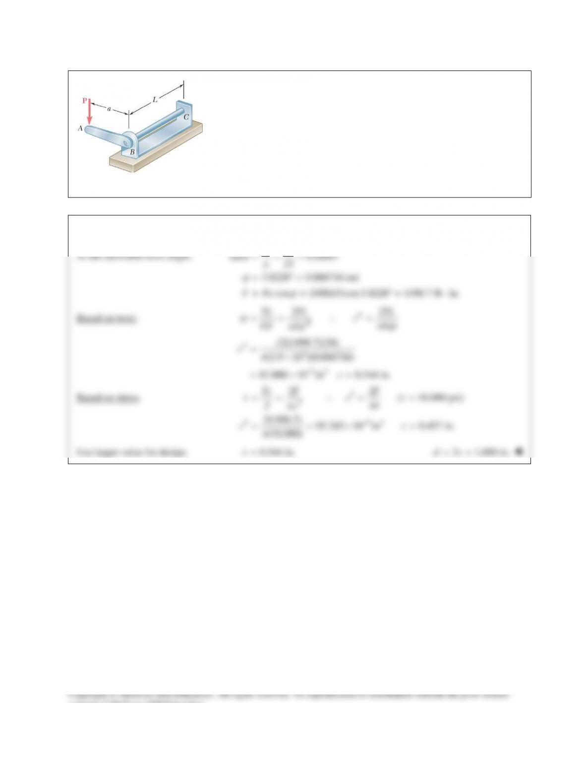
PROBLEM 10.40
The solid cylindrical rod BC of length L = 24 in. is attached to the rigid
lever AB of length a = 15 in. and to the support at C. Design specifications
require that the displacement of A not exceed 1 in. when a 100–lb force P is
applied at A. For the material indicated, determine the required diameter of
the rod.
Aluminum:
τ
all = 10 ksi, G = 3.9 × 10⁶ psi.
SOLUTION
At the allowable twist angle,
1
sin 0.06667
15
3.8226 0.066716 rad
cos (100)(15)cos3.8226 1496.7 lb in.
a
T Pa
ϕ
ϕ
ϕ
∆
= = =
= °=
= = °= ⋅
Based on twist.
4
4
22
ϕπϕ
π
== ∴=
TL TL TL
c
GJ G
Gc
46
34
(2)(1496.7)(24)
(3.9 10 )(0.066716)
87.888 10 in 0.544 in.
π
−
=×
=×=
c
c
Based on stress.
3
3
3 33
22
( 10,000 psi)
2(1496.7) 95.283 10 in 0.457 in.
(10,000)
ττ
πτ
π
π
−
== ∴= =
==×=
Tc T T
c
Jc
cc
Use larger value for design.
0.544 in.=c
2 1.089 in.dc= =
consent of McGraw–Hill Education.
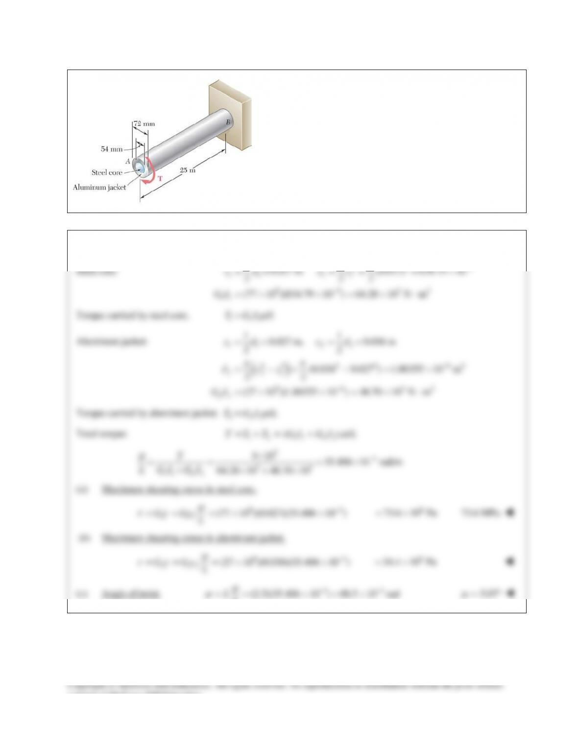
PROBLEM 10.41
A torque of magnitude
4 kN mT= ⋅
is applied at end A of the
composite shaft shown. Knowing that the modulus of rigidity
is 77 GPa for the steel and 27 GPa for the aluminum,
determine (a) the maximum shearing stress in the steel core,
(b) the maximum shearing stress in the aluminum jacket,
(c) the angle of twist at A.
SOLUTION
Steel core:
44 9
11 11
9 9 32
11
10.027 m (0.027) 834.79 10
2 22
(77 10 )(834.79 10 ) 64.28 10 N m
cd Jc
GJ
ππ
−
−
= = = = = ×
=× ×=× ⋅
Torque carried by steel core.
1 11
/T GJ L
ϕ
=
Aluminum jacket:
( )
11 2 2
4 4 4 4 64
2 21
9 6 32
22
11
0.027 m, 0.036 m
22
(0.036 0.027 ) 1.80355 10 m
22
(27 10 )(1.80355 10 ) 48.70 10 N m
cd cd
J cc
GJ
ππ
−
−
= = = =
= −= − = ×
=× ×=×⋅
Torque carried by aluminum jacket.
2 22
/T GJ L
ϕ
=
Total torque:
1 2 11 2 2
( )/T T T GJ GJ L
ϕ
=+= +
33
33
11 2 2
4 10 35.406 10 rad/m
64.28 10 48.70 10
T
L GJ GJ
ϕ
−
×
= = = ×
+×+ ×
(a) Maximum shearing stress in steel core.
93
1 11
(77 10 )(0.027)(35.406 10 )G Gc L
ϕ
τγ
−
===××
6
73.6 10 Pa= ×
73.6 MPa
(b) Maximum shearing stress in aluminum jacket.
93
2 22
(27 10 )(0.036)(35.406 10 )G Gc L
ϕ
τγ
−
===××
6
34.4 10 Pa= ×
(c) Angle of twist.
33
(2.5)(35.406 10 ) 88.5 10 radLL
ϕ
ϕ
−−
== ×=×
5.07
ϕ
= °
consent of McGraw–Hill Education.
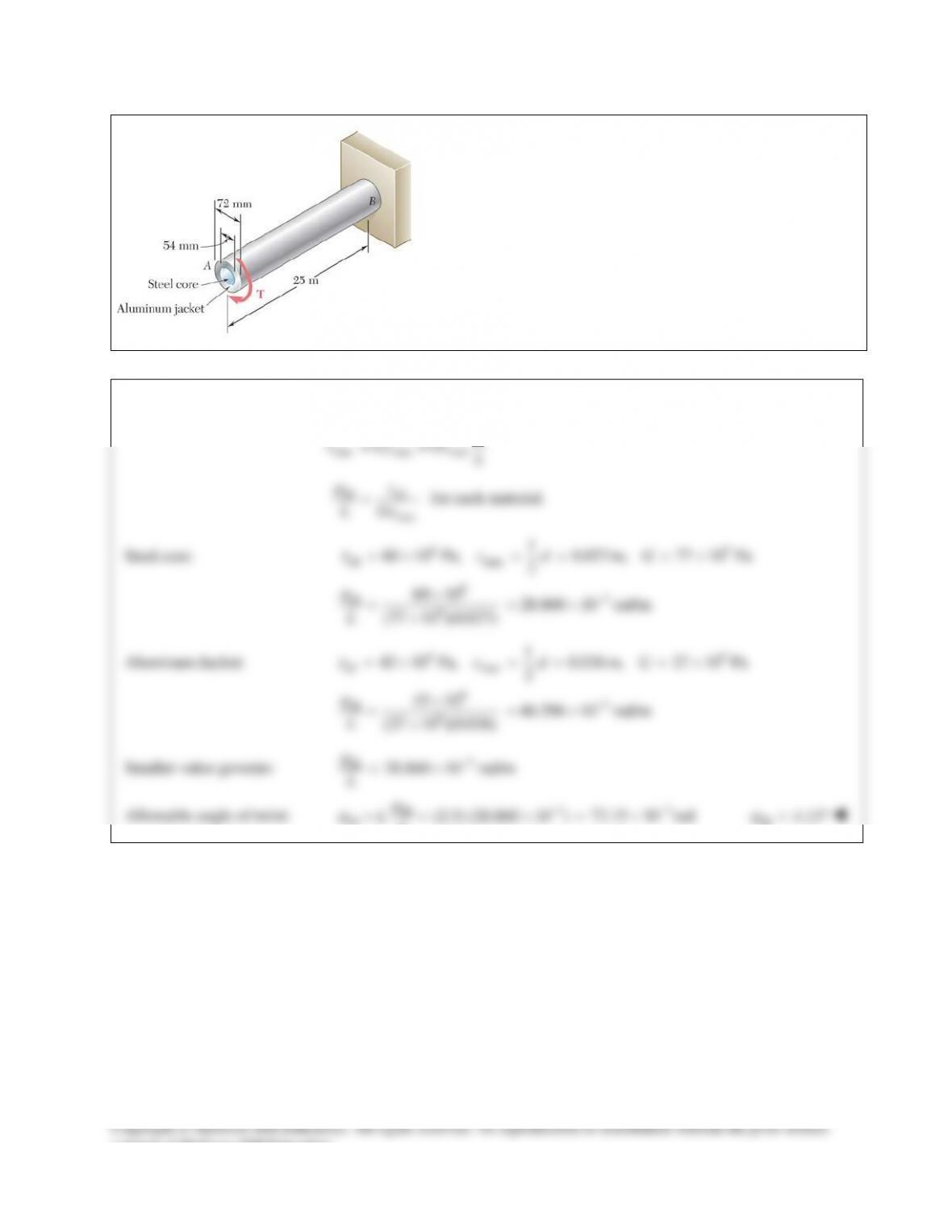
PROBLEM 10.42
The composite shaft shown is to be twisted by applying a torque
T at end A. Knowing that the modulus of rigidity is 77 GPa for
the steel and 27 GPa for the aluminum, determine the largest
angle through which end A can be rotated if the following
allowable stresses are not to be exceeded:
steel 60 MPa
t
=
and
aluminum
45MPa.
t
=
SOLUTION
max max max
G Gc L
ϕ
tγ
= =
all all
max
L Gc
ϕt
=
for each material.
Steel core:
69
all max
63
all 9
1
60 10 Pa 0.027m, 77 10 Pa
2
60 10 28.860 10 rad/m
(77 10 )(0.027)
,c d G
L
t
ϕ
−
=×===×
×
= = ×
×
Aluminum Jacket:
69
all max
63
all 9
1
45 10 Pa 0.036m, 27 10 Pa
2
45 10 46.296 10 rad/m
(27 10 )(0.036)
,c d G
L
t
ϕ
−
=×===×
×
= = ×
×
Smaller value governs:
3
all
28.860 10 rad/m
L
ϕ
−
= ×
Allowable angle of twist:
3
all
all
(2.5) (28.860 10 )LL
ϕ
ϕ
−
= = ×
3
72.15 10 rad
−
= ×
all 4.13
ϕ
= °
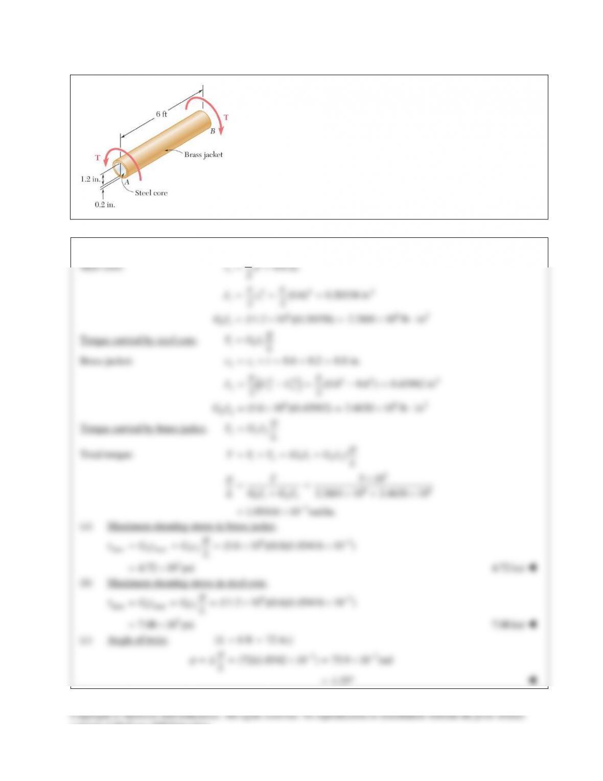
PROBLEM 10.43
The composite shaft shown consists of a 0.2–in.–thick brass
jacket (G = 5.6 × 10⁶ psi) bonded to a 1.2–in.–diameter steel core
(Gsteel = 11.2 × 10⁶ psi). Knowing that the shaft is subjected to
5-kip ⋅ in. torques, determine (a) the maximum shearing stress in
the brass jacket, (b) the maximum shearing stress in the steel
core, (c) the angle of twist of end B relative to end A.
SOLUTION
Steel core:
1
44 4
11
6 62
11
10.6 in.
2
(0.6) 0.20358 in
22
(11.2 10 )(0.20358) 2.2801 10 lb in
cd
Jc
GJ
ππ
= =
= = =
=× = ×⋅
Torque carried by steel core.
1 11
T GJ L
ϕ
=
Brass jacket:
( )
21
44 4 4 4
2 21
6 62
22
0.6 0.2 0.8 in.
(0.8 0.6 ) 0.43982 in
22
(5.6 10 )(0.43982) 2.4630 10 lb in
ππ
= += + =
= −= − =
=× = ×⋅
c ct
J CC
GJ
Torque carried by brass jacket.
2 22
T GJ L
ϕ
=
Total torque:
1 2 11 2 2
3
66
11 2 2
3
()
5 10
2.2801 10 2.4630 10
1.05416 10 rad/in.
ϕ
ϕ
−
=+= +
×
= =
+×+ ×
= ×
T T T GJ GJ L
T
L GJ GJ
(a) Maximum shearing stress in brass jacket.
63
max 2 max 2 2
(5.6 10 )(0.8)(1.05416 10 )
ϕ
τγ
−
===××G Gc L
3
4.72 10 psi= ×
4.72 ksi
(b) Maximum shearing stress in steel core.
63
max 1 max 1 1 (11.2 10 )(0.6)(1.05416 10 )
ϕ
τγ
−
===××G Gc L
3
7.08 10 psi= ×
7.08 ksi
(c) Angle of twist.
( 6 ft 72 in.)L= =
33
(72)(1.0542 10 ) 75.9 10 radLL
ϕ
ϕ
−−
== ×=×
4.35= °
consent of McGraw–Hill Education.
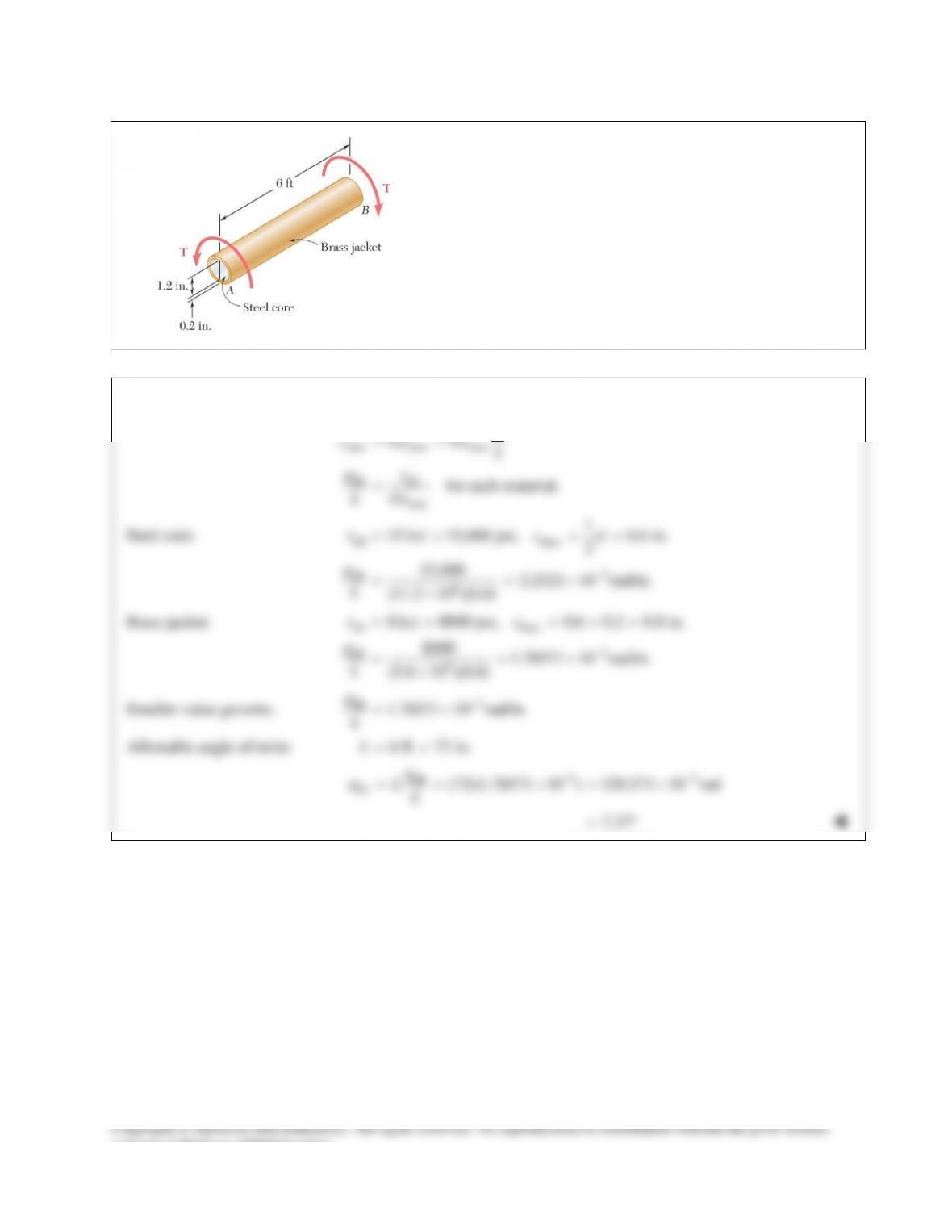
PROBLEM 10.44
The composite shaft shown consists of a 0.2–in.–thick brass
jacket (G = 5.6 × 10⁶ psi) bonded to a 1.2–in.–diameter steel
core (Gsteel = 11.2 × 10⁶ psi). Knowing that the shaft is being
subjected to the torques shown, determine the largest angle
through which it can be twisted if the following allowable
stresses are not to be exceeded:
t
steel = 15 ksi and
t
brass = 8 ksi.
SOLUTION
max max max
all all
max
for each material.
ϕ
tγ
ϕt
= =
=
G Gc L
L Gc
Steel core:
all max
3
all 6
1
15 ksi 15,000 psi, 0.6 in.
2
15,000 2.2321 10 rad/in.
(11.2 10 )(0.6)
t
ϕ
−
= = = =
= = ×
×
cd
L
Brass jacket:
all max
3
all 6
8 ksi 8000 psi, 0.6 0.2 0.8 in.
8000 1.78571 10 rad/in.
(5.6 10 )(0.8)
t
ϕ
−
= = =+=
= = ×
×
c
L
Smaller value governs.
3
all
1.78571 10 rad/in.
L
ϕ
−
= ×
Allowable angle of twist:
6 ft 72 in.L= =
33
all
all (72)(1.78571 10 ) 128.571 10 radLL
ϕ
ϕ
−−
= = ×= ×
7.37= °
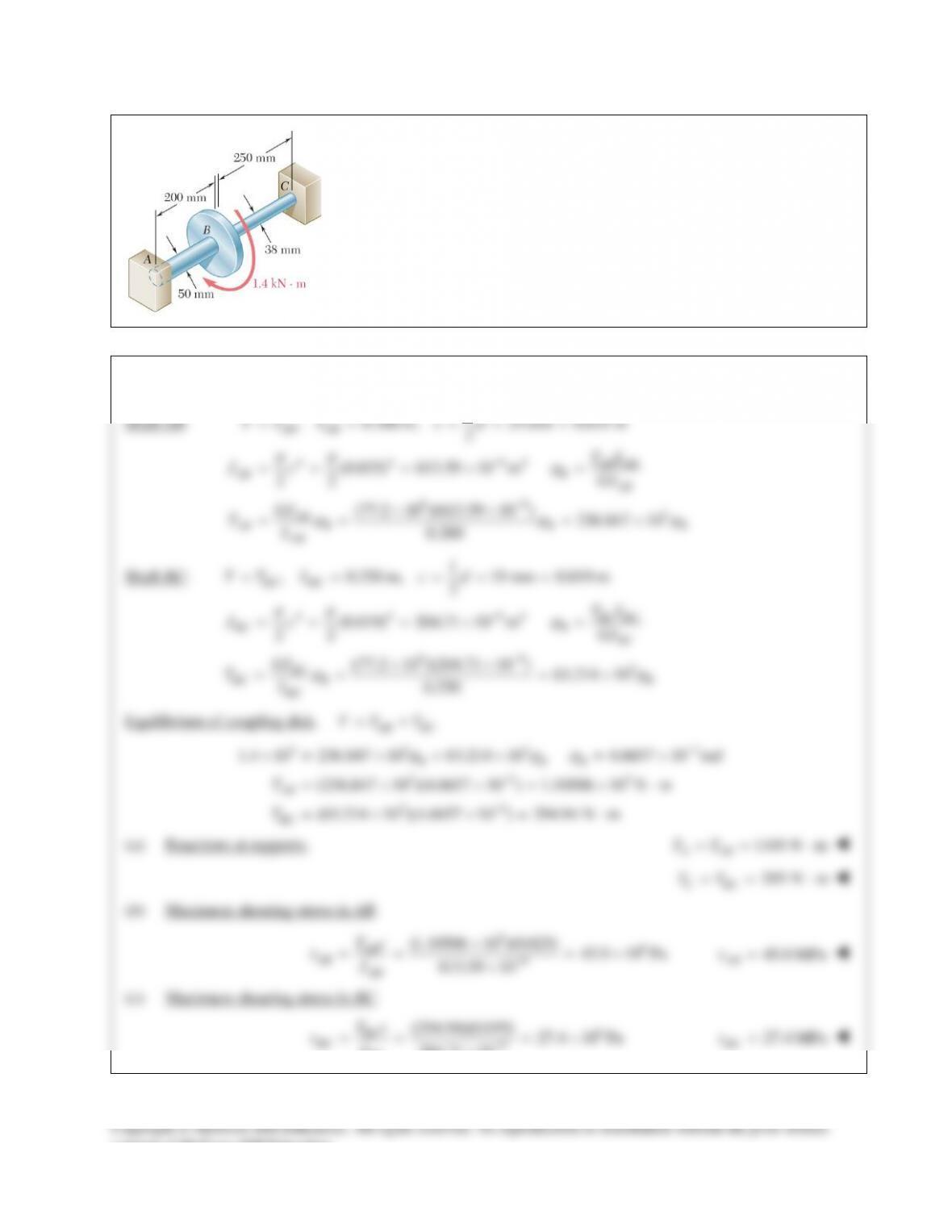
PROBLEM 10.45
Two solid steel shafts
( 77.2 GPa)=G
are connected to a coupling disk B and
to fixed supports at A and C. For the loading shown, determine (a) the
reaction at each support, (b) the maximum shearing stress in shaft AB, (c) the
maximum shearing stress in shaft BC.
SOLUTION
Shaft AB:
4 4 94
99 3
1
, 0.200 m, 25 mm 0.025 m
2
(0.025) 613.59 10 m
22
(77.2 10 )(613.59 10 ) 236.847 10
0.200
AB AB
AB AB
AB B AB
AB
AB B B B
AB
TT L c d
TL
Jc GJ
GJ
TL
ππ ϕ
ϕ ϕϕ
−
−
= = = = =
===×=
××
= = = ×
Shaft BC:
4 4 94
99 3
1
, 0.250 m, 19 mm 0.019 m
2
(0.019) 204.71 10 m
22
77.2 10 )(204.71 10 ) 63.214 10
0.250
BC BC
BC BC
BC B BC
BC
BC B B
BC
TT L c d
TL
Jc GJ
GJ
TL
ππ ϕ
ϕϕ
−
−
= = = = =
===×=
(× ×
= = = ×
Equilibrium of coupling disk.
AB BC
TT T= +
33 3 3
33 3
33
1.4 10 236.847 10 63.214 10 4.6657 10 rad
(236.847 10 )(4.6657 10 ) 1.10506 10 N m
(63.214 10 )(4.6657 10 ) 294.94 N m
ϕ ϕϕ
−
−
−
×= × + × = ×
= × ×= ×⋅
= × ×= ⋅
B BB
AB
BC
T
T
(a) Reactions at supports.
1105 N m
A AB
TT= = ⋅
295 N m
C BC
TT= = ⋅
(b) Maximum shearing stress in AB.
36
9
(1.10506 10 )(0.025) 45.0 10 Pa
613.59 10
AB
AB AB
Tc
J
τ
−
×
= = = ×
×
45.0 MPa
AB
τ
=
(c) Maximum shearing stress in BC.
6
9
(294.94)(0.019) 27.4 10 Pa
204.71 10
BC
BC BC
Tc
J
τ
−
= = = ×
×
27.4 MPa
BC
τ
=
PROBLEM 10.46
Solve Prob. 10.45, assuming that the shaft AB is replaced by a hollow
shaft of the same outer diameter and 25–mm inner diameter.
PROBLEM 10.45 Two solid steel shafts
( 77.2 GPa)=G
are connected
to a coupling disk B and to fixed supports at A and C. For the loading
shown, determine (a) the reaction at each support, (b) the maximum
shearing stress in shaft AB, (c) the maximum shearing stress in shaft BC.
SOLUTION
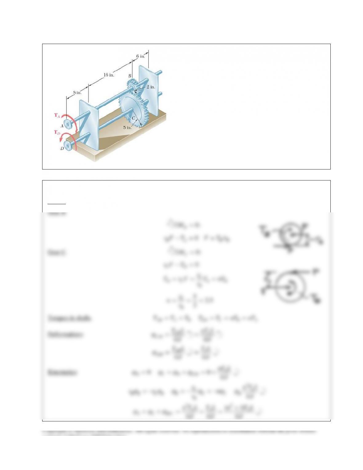
PROBLEM 10.47
The design specifications for the gear–and–shaft system
shown require that the same diameter be used for both
shafts, and that the angle through which pulley A will
rotate when subjected to a 2-kip ⋅ in. torque
A
T
while
pulley D is held fixed will not exceed
7.5 .°
Determine
the required diameter of the shafts if both shafts are made
of a steel with
6
11.2 10 psiG= ×
and
all 12 ksi.
τ
=
SOLUTION
Statics:
consent of McGraw–Hill Education.
SOLUTION Continued
Diameter based on stress.
Largest torque:
m CD A
T T nT= =
33
all
3
3
3
33
212 10 psi, 2 10 lb in
2 (2)(2.5)(2 10 ) 0.6425 in., 2 1.285 in.
(12 10 )
mA
mm A
A
m
T c nT T
Jc
nT
c dc
τ ττ
p
pτ p
== ==× =×⋅
×
= = = = =
×
Diameter based on rotation limit.
2
4
3
4
46
7.5 0.1309 rad
( 1) (2)(7.25) 8 16 24 in.
(2)(7.25) (2)(7.25)(2 10 )(24) 0.62348 in., 2 1.247 in.
(11.2 10 )(0.1309)
AA
A
n TL TL L
GJ cG
TL
c dc
G
ϕ
ϕp
pϕ p
= °=
+
= = =+=
×
= = = = =
×
Choose the larger diameter.
1.285 in.d=