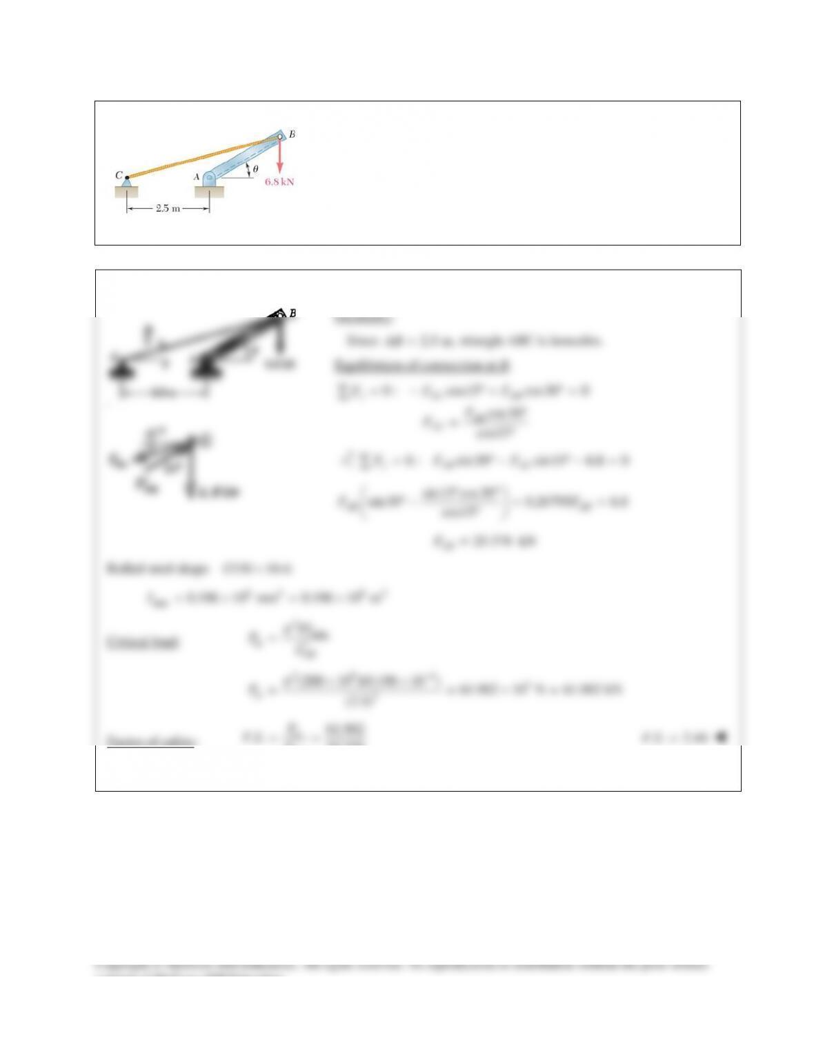
PROBLEM 16.54
Member AB consists of a single
C130 10.4
×
steel channel of length
2.5 m. Knowing that the pins at A and B pass through the centroid of the
cross section of the channel, determine the factor of safety for the load
shown with respect to buckling in the plane of the figure when
30
θ
= °
.
Use Euler’s formula with
200 GPa.E=
SOLUTION
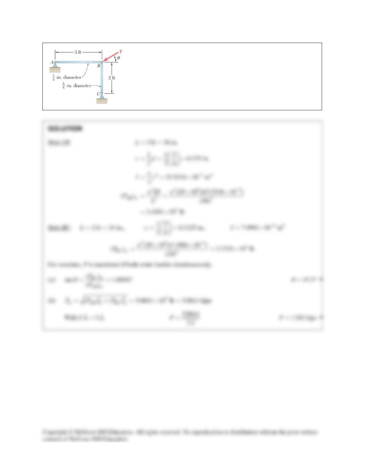
PROBLEM 16.55
(a) Considering only buckling in the plane of the structure shown and
using Euler’s formula, determine the value of
θ
between 0° and 90° for
which the allowable magnitude of the load P is maximum. (b) Determine
the corresponding maximum value of P knowing that a factor of safety of
3.2 is required. Use
6
29 10 psi.E= ×
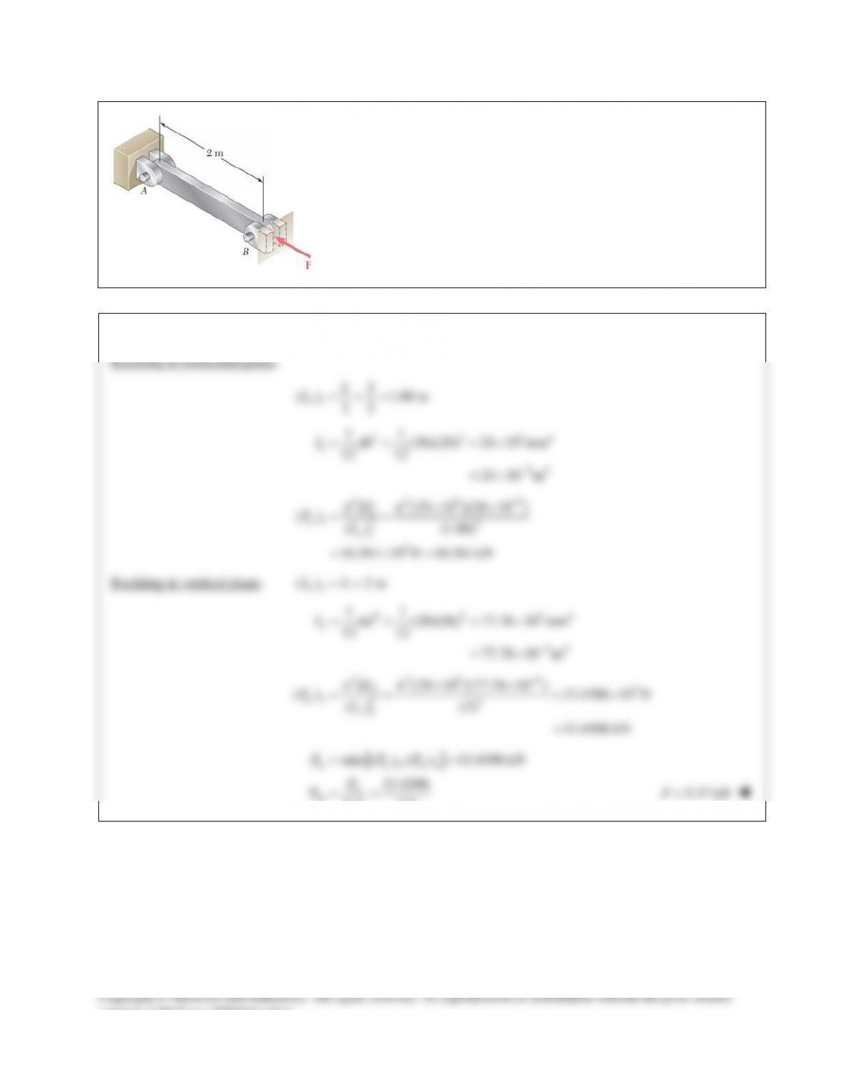
PROBLEM 16.56
The uniform aluminum bar AB has a
20 36×
–mm rectangular cross
section and is supported by pins and brackets as shown. Each end of the
bar may rotate freely about a horizontal axis through the pin, but rotation
about a vertical axis is prevented by the brackets. Using E
70=
GPa,
determine the allowable centric load P if a factor of safety of 2.5 is
required.
SOLUTION
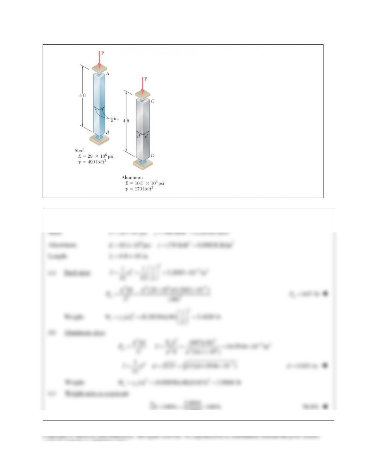
PROBLEM 16.57
Determine (a) the critical load for the steel strut, (b) the
dimension d for which the aluminum strut will have the
same critical load. (c) Express the weight of the
aluminum strut as a percent of the weight of the steel
strut.
SOLUTION
6 33
PROBLEM 16.58
A compression member has the cross section shown and an effective
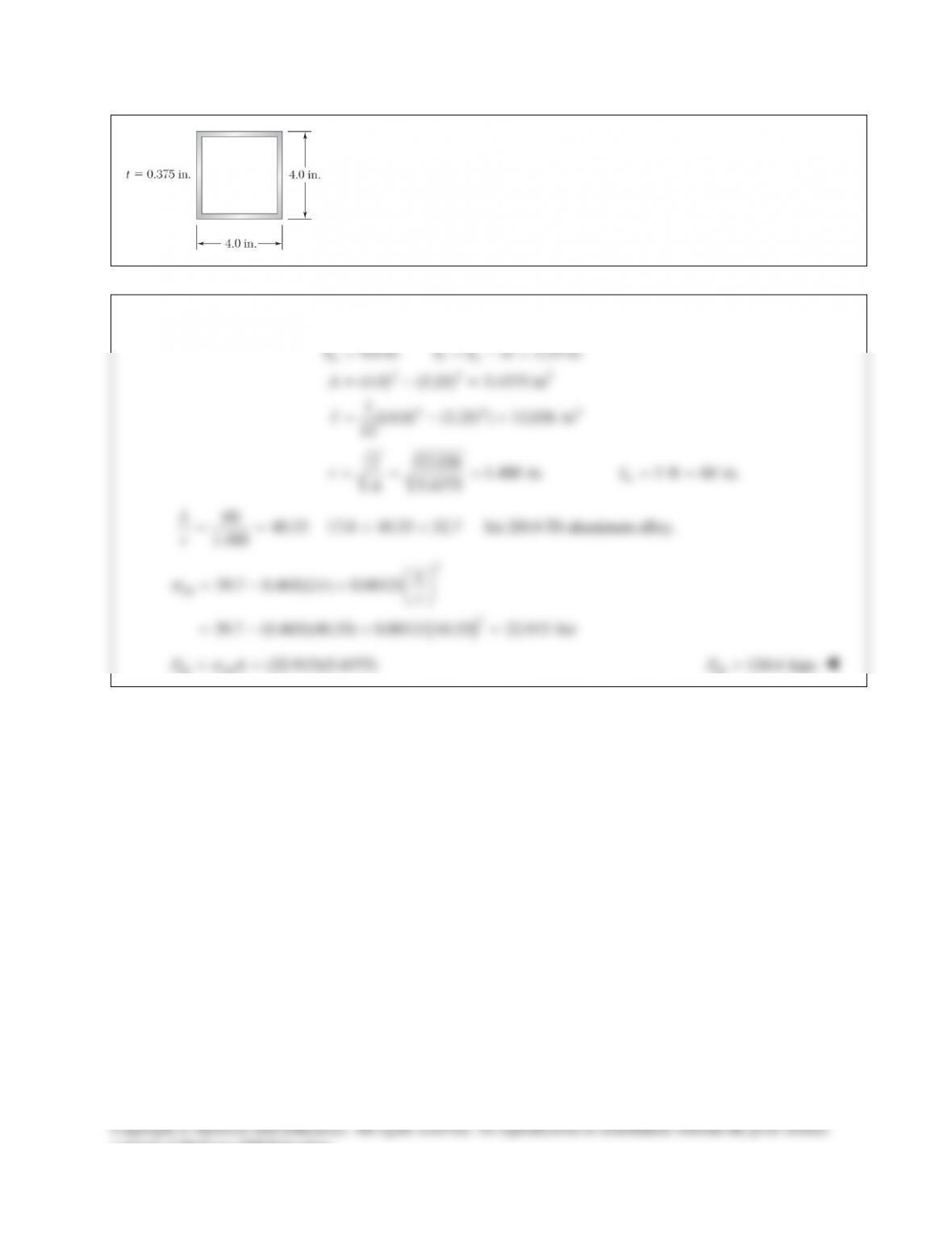
length of 5 ft. Knowing that the aluminum alloy used is 2014–T6,
determine the allowable centric load.
SOLUTION
22 2
44 4
4.0 in. 2 3.25 in.
(4.0) (3.25) 5.4375 in
1[(4.0) (3.25) ] 12.036 in
12
o io
b bb t
A
I
= =−=
=−=
= −=
12.036 1.488 in.
5.4375
I
rA
= = =
5ft 60in.
e
L= =
60 40.33 17.0 40.33 52.7
1.488
L
r== <<
for 2014-T6 aluminum alloy.
( )
2
all
2
39.7 0.465( / ) 0.00121
39.7 (0.465)(40.33) 0.00121 40.33 22.915 ksi
L
Lr r
s
=−+
=−+ =
all all
(22.915)(5.4375)
PA
s
= =
all 124.6 kips
P=
PROBLEM 16.59
A column is made from half of a
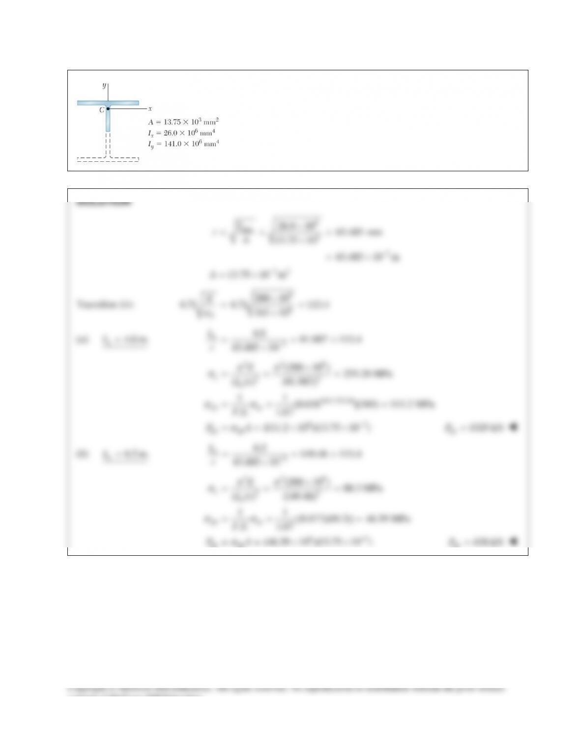
W360 216×
rolled–steel shape, with
the geometric properties as shown. Using allowable stress design,
determine the allowable centric load if the effective length of the
column is (a) 4.0 m, (b) 6.5 m. Use
345 MPa
σ
=
Y
and
200 GPa.=E
PROBLEM 16.60
A column of 4.6–m effective length must carry a centric load of 525 kN. Knowing that
345 MPa
σ
=
Y
and
200 GPa,E=
use allowable stress design to select the wide–flange shape of 200–mm nominal depth that
should be used.
PROBLEM 16.55
(a) Considering only buckling in the plane of the structure shown and
using Euler’s formula, determine the value of
θ
between 0° and 90° for
which the allowable magnitude of the load P is maximum. (b) Determine
the corresponding maximum value of P knowing that a factor of safety of
3.2 is required. Use
6
29 10 psi.E= ×
PROBLEM 16.56
The uniform aluminum bar AB has a
20 36×
–mm rectangular cross
section and is supported by pins and brackets as shown. Each end of the
bar may rotate freely about a horizontal axis through the pin, but rotation
about a vertical axis is prevented by the brackets. Using E
70=
GPa,
determine the allowable centric load P if a factor of safety of 2.5 is
required.
SOLUTION
PROBLEM 16.57
Determine (a) the critical load for the steel strut, (b) the
dimension d for which the aluminum strut will have the
same critical load. (c) Express the weight of the
aluminum strut as a percent of the weight of the steel
strut.
SOLUTION
6 33
PROBLEM 16.58
A compression member has the cross section shown and an effective
length of 5 ft. Knowing that the aluminum alloy used is 2014–T6,
determine the allowable centric load.
SOLUTION
22 2
44 4
4.0 in. 2 3.25 in.
(4.0) (3.25) 5.4375 in
1[(4.0) (3.25) ] 12.036 in
12
o io
b bb t
A
I
= =−=
=−=
= −=
12.036 1.488 in.
5.4375
I
rA
= = =
5ft 60in.
e
L= =
60 40.33 17.0 40.33 52.7
1.488
L
r== <<
for 2014-T6 aluminum alloy.
( )
2
all
2
39.7 0.465( / ) 0.00121
39.7 (0.465)(40.33) 0.00121 40.33 22.915 ksi
L
Lr r
s
=−+
=−+ =
all all
(22.915)(5.4375)
PA
s
= =
all 124.6 kips
P=
PROBLEM 16.59
A column is made from half of a
W360 216×
rolled–steel shape, with
the geometric properties as shown. Using allowable stress design,
determine the allowable centric load if the effective length of the
column is (a) 4.0 m, (b) 6.5 m. Use
345 MPa
σ
=
Y
and
200 GPa.=E
PROBLEM 16.60
A column of 4.6–m effective length must carry a centric load of 525 kN. Knowing that
345 MPa
σ
=
Y
and
200 GPa,E=
use allowable stress design to select the wide–flange shape of 200–mm nominal depth that
should be used.