PROBLEM 8.37
Three
3
4
–in.–diameter steel bolts are to be used to attach the steel plate shown to
a wooden beam. Knowing that the plate will support a load P = 24 kips and that
the ultimate shearing stress for the steel used is 52 ksi, determine the factor of
safety for this design.
SOLUTION
For each bolt,
2
22
30.44179 in
4 44
Ad
ππ
= = =
(0.44179)(52)
22.973 kips
UU
PA
τ
= =
=
For the three bolts,
(3)(22.973) 68.919 kips
U
P= =
Factor of safety:
68.919
.. 24
U
P
FS P
= =
. . 2.87FS =
consent of McGraw–Hill Education.
PROBLEM 8.38
Two plates, each
1
8
in. thick, are used to splice a plastic strip as shown.
Knowing that the ultimate shearing stress of the bonding between the
surface is 130 psi, determine the factor of safety with respect to shear
when
325 lb.P=
SOLUTION
Bond area: (See figure)
2
1(2.25)(0.75) (2.25)(0.625) 2.25 in
2
A= +=
2 (2)(2.25)(130) 585 lb.
UU
PA
τ
= = =
585
. . 1.800
325
U
P
FS P
= = =
consent of McGraw–Hill Education.
PROBLEM 8.39
A load P is supported as shown by a steel pin that has been inserted in a
short wooden member hanging from the ceiling. The ultimate strength of
the wood used is 60 MPa in tension and 7.5 MPa in shear, while the
ultimate strength of the steel is 145 MPa in shear. Knowing that
40 mm,b=
55 mm,c=
and
12 mm,d=
determine the load P if an
overall factor of safety of 3.2 is desired.
SOLUTION
Based on double shear in pin,
2
26 3
22
4
(2)(0.012) (145 10 ) 32.80 10 N
4
π
ττ
π
= =
= ×= ×
UU U
PA d
Based on tension in wood,
6
3
()
(0.040)(0.040 0.012)(60 10 )
67.2 10 N
UU U
P A wb d
σσ
= = −
= −×
= ×
Based on double shear in the wood,
6
3
2 2 (2)(0.040)(0.055)(7.5 10 )
33.0 10 N
ττ
= = = ×
= ×
UU U
P A wc
Use smallest
3
32.8 10 N= ×
U
P
Allowable:
33
32.8 10 10.25 10 N
. . 3.2
×
= = = ×
U
P
PFS
10.25 kN
consent of McGraw–Hill Education.
PROBLEM 8.40
For the support of Prob. 8.39, knowing that the diameter of the pin is d = 16
mm and that the magnitude of the load is P = 20 kN, determine (a) the
factor of safety for the pin, (b) the required values of b and c if the factor of
safety for the wooden member is the same as that found in part a for the
pin.
PROBLEM 8.39
A load P is supported as shown by a steel pin that has been inserted in a
short wooden member hanging from the ceiling. The ultimate strength of
the wood used is 60 MPa in tension and 7.5 MPa in shear, while the
ultimate strength of the steel is 145 MPa in shear. Knowing that b = 40
mm, c = 55 mm, and d = 12 mm, determine the load P if an overall factor
of safety of 3.2 is desired.
SOLUTION
3
20 kN 20 10 N= = ×P
(a) Pin:
2 2 62
(0.016) 201.06 10 m
44
Ad
ππ
−
= = = ×
Double shear:
22
U
U
PP
AA
ττ
= =
66 3
2 (2)(201.16 10 )(145 10 ) 58.336 10 N
UU
PA
τ
−
= = × ×= ×
3
3
58.336 10
. . 2.92
20 10
U
P
FS P
×
= = =
×
. . 2.92FS =
(b) Tension in wood:
3
58.336 10 N for same F.S.
U
P= ×
where 40 mm 0.040 m
()
UU
UPP w
A wb d
σ
= = = =
−
33
6
58.336 10
0.016 40.3 10 m
(0.040)(60 10 )
U
U
P
bdw
σ
×
=+=+ =×
×
40.3 mmb=
Shear in wood:
3
58.336 10 N for same F.S.
U
P= ×
Double shear: each area is
A wc=
22
τ
= =
UU
U
PP
A wc
33
6
58.336 10 97.2 10 m
2(2)(0.040)(7.5 10 )
U
U
P
cw
τ
−
×
= = = ×
×
97.2 mmc=
consent of McGraw–Hill Education.
PROBLEM 8.41
A steel plate
5
16
in. thick is embedded in a horizontal concrete slab and is
used to anchor a high–strength vertical cable as shown. The diameter of
the hole in the plate is
3
4
in.,
the ultimate strength of the steel used is 36 ksi,
and the ultimate bonding stress between plate and concrete is 300 psi.
Knowing that a factor of safety of 3.60 is desired when P = 2.5 kips,
determine (a) the required width a of the plate, (b) the minimum depth b
to which a plate of that width should be embedded in the concrete slab.
(Neglect the normal stresses between the concrete and the lower end of
the plate.)
SOLUTION
Based on tension in plate:
()
()
..
σ
σ
= −
=
−
= =
UU
UU
A a dt
PA
P a dt
FS
PP
Solving for a,
( )
5
16
( . .) 3 (3.60)(2.5)
4(36)
U
FS P
ad t
σ
=+=+
(a)
1.550 in.
=a
Based on shear between plate and concrete slab,
perimeter depth 2( ) 0.300 ksi
U
A a tb
t
= ×=+ =
2 ( ) ..
U
UU U
P
P A a tb FS P
tt
==+=
Solving for b,
( )
5
16
( . .) (3.6)(2.5)
2( ) (2) 1.550 (0.300)
U
FS P
bat
t
= =
++
(b)
8.05 in.=b
consent of McGraw–Hill Education.
PROBLEM 8.42
Determine the factor of safety for the cable anchor in Prob. 8.41 when
3 kips,P=
knowing that
2 in.a=
and
7.5 in.b=
PROBLEM 8.41 A steel plate
5
16
in, thick is embedded in a horizontal
concrete slab and is used to anchor a high–strength vertical cable as
shown. The diameter of the hole in the plate is
3
4
in.,
the ultimate
strength of the steel used is 36 ksi, and the ultimate bonding stress
between plate and concrete is 300 psi. Knowing that a factor of safety of
3.60 is desired when
2.5 kips,P=
determine (a) the required width a of
the plate, (b) the minimum depth b to which a plate of that width should
be embedded in the concrete slab. (Neglect the normal stresses between
the concrete and the lower end of the plate.)
SOLUTION
Based on tension in plate:
2
()
35
2 0.3906 in
4 16
A a dt= −
=−=
(36)(0.3906) 14.06 kips
UU
PA
s
=
= =
14.06
. . 4.69
3
= = =
U
P
FS P
5
perimeter depth 2( ) 2 2 (7.5)
16
= × = += +
A a tb
2
34.69 in 0.300 ksi
U
A
τ
= =
(0.300)(34.69) 10.41kips
UU
PA
τ
= = =
10.41
. . 3.47
3
U
P
FS P
= = =
consent of McGraw–Hill Education.
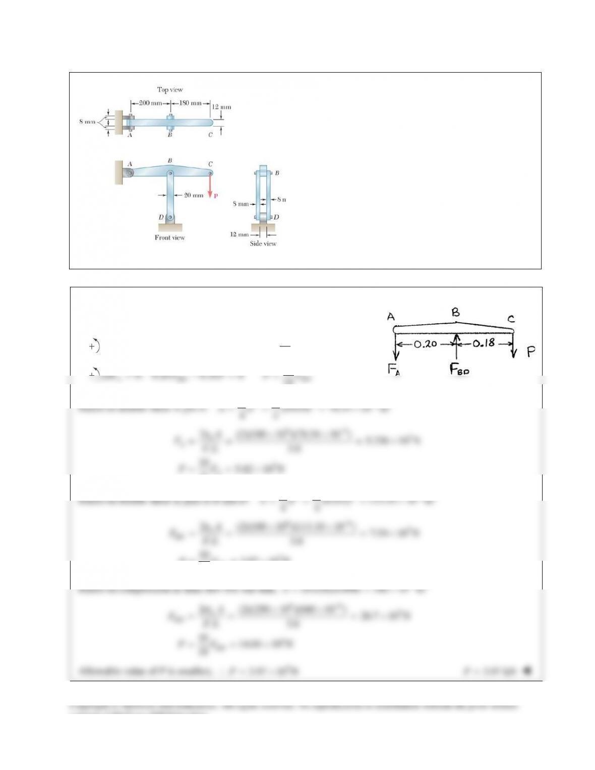
PROBLEM 8.43
In the structure shown, an 8–mm–diameter pin is
used at A, and 12–mm–diameter pins are used at B
and D. Knowing that the ultimate shearing stress is
100 MPa at all connections and that the ultimate
normal stress is 250 MPa in each of the two links
joining B and D, determine the allowable load P if
an overall factor of safety of 3.0 is desired.
SOLUTION
Statics: Use ABC as free body.
10
0 : 0.20 0.18 0 9
BA A
M F P PFΣ= − = =
10
0 : 0.20 0.38 0 19
A BD BD
M F P PFΣ= − = =
Based on double shear in pin A:
2 2 62
(0.008) 50.266 10 m
44
ππ
−
= = = ×Ad
663
3
2(2)(100 10 )(50.266 10 ) 3.351 10 N
. . 3.0
10 3.72 10 N
9
τ
−
××
= = = ×
= = ×
U
A
A
A
FFS
PF
Based on double shear in pins at B and D:
2 2 62
(0.012) 113.10 10 m
44
ππ
−
= = = ×Ad
66
3
3
2(2)(100 10 )(113.10 10 ) 7.54 10 N
. . 3.0
10 3.97 10 N
19
U
BD
BD
A
FFS
PF
τ
−
××
= = = ×
= = ×
Based on compression in links BD: For one link,
62
(0.020)(0.008) 160 10 m
−
= = ×A
66 3
3
2 (2)(250 10 )(160 10 ) 26.7 10 N
. . 3.0
10 14.04 10 N
19
σ
−
××
= = = ×
= = ×
U
BD
BD
A
FFS
PF
Allowable value of P is smallest, ∴
3
3.72 10 N= ×P
3.72 kN=P
Copyright © McGraw–Hill Education. All rights reserved. No reproduction or distribution without the prior written
consent of McGraw–Hill Education.
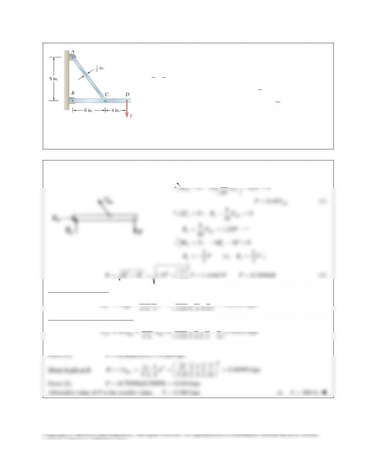
PROBLEM 8.45
Link AC is made of a steel with a 65–ksi ultimate normal stress and has
a
11
42
×
–in. uniform rectangular cross section. It is connected to a
support at A and to member BCD at C by
3
8
–in.–diameter pins, while
member BCD is connected to its support at B by a
5
16
–in.–diameter pin;
all of the pins are made of a steel with a 25–ksi ultimate shearing stress
and are in single shear. Knowing that a factor of safety of 3.25 is
desired, determine the largest load P that can be applied at D. Note that
link AC is not reinforced around the pin holes.
SOLUTION
Use free body BCD.
8
0 : (6) 10 0
10
B AC
M FP
= −=
0.48
AC
PF=
(1)
6
0: 0
10
x x AC
F BFΣ= − =
61.25
10
= =
x AC
BF P
0: 6 4 0= − −=
Cy
M BP
22
i.e.
33
yy
B P BP
=−=
2
22 2
2
1.25 1.41667 0.70588
3
= += + = =
xy
B BB P P P B
(2)
Shear in pins at A and C.
2
2
pin 25 3 0.84959 kips
. . 4 3.25 4 8
U
AC
FA d
FS
τp p
τ
= = = =
Tension on net section of A and C.
net net 65 1 1 3 0.625 kips
. . 3.25 4 2 8
U
AC
FA A
FS
s
s
= = = −=
Smaller value of FAC is 0.625 kips.
From (1),
(0.48)(0.625) 0.300 kipsP= =
Shear in pin at B.
2
2
pin 25 5 0.58999 kips
. . 4 3.25 4 16
U
BA d
FS
τp p
τ
= = = =
From (2),
(0.70588)(0.58999) 0.416 kipsP= =
Allowable value of P is the smaller value.
0.300 kipsP=
or
300 lbP=
consent of McGraw–Hill Education.
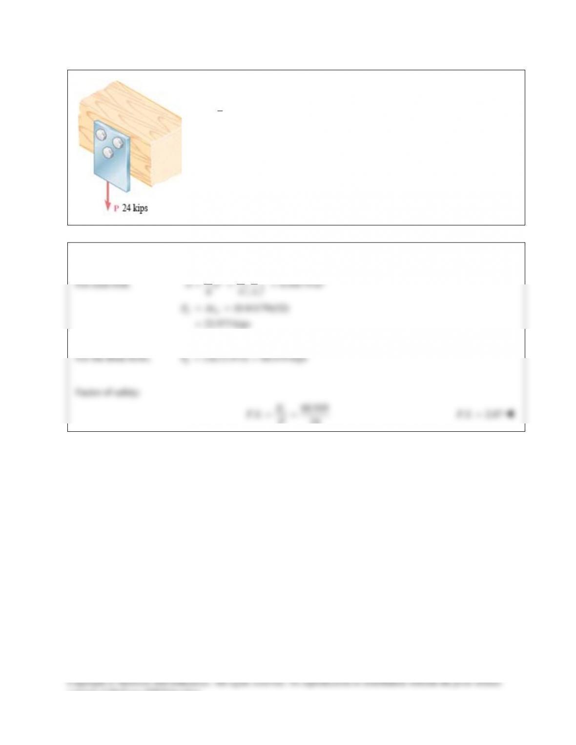
PROBLEM 8.37
Three
3
4
–in.–diameter steel bolts are to be used to attach the steel plate shown to
a wooden beam. Knowing that the plate will support a load P = 24 kips and that
the ultimate shearing stress for the steel used is 52 ksi, determine the factor of
safety for this design.
SOLUTION
For each bolt,
2
22
30.44179 in
4 44
Ad
ππ
= = =
(0.44179)(52)
22.973 kips
UU
PA
τ
= =
=
For the three bolts,
(3)(22.973) 68.919 kips
U
P= =
Factor of safety:
68.919
.. 24
U
P
FS P
= =
. . 2.87FS =
consent of McGraw–Hill Education.
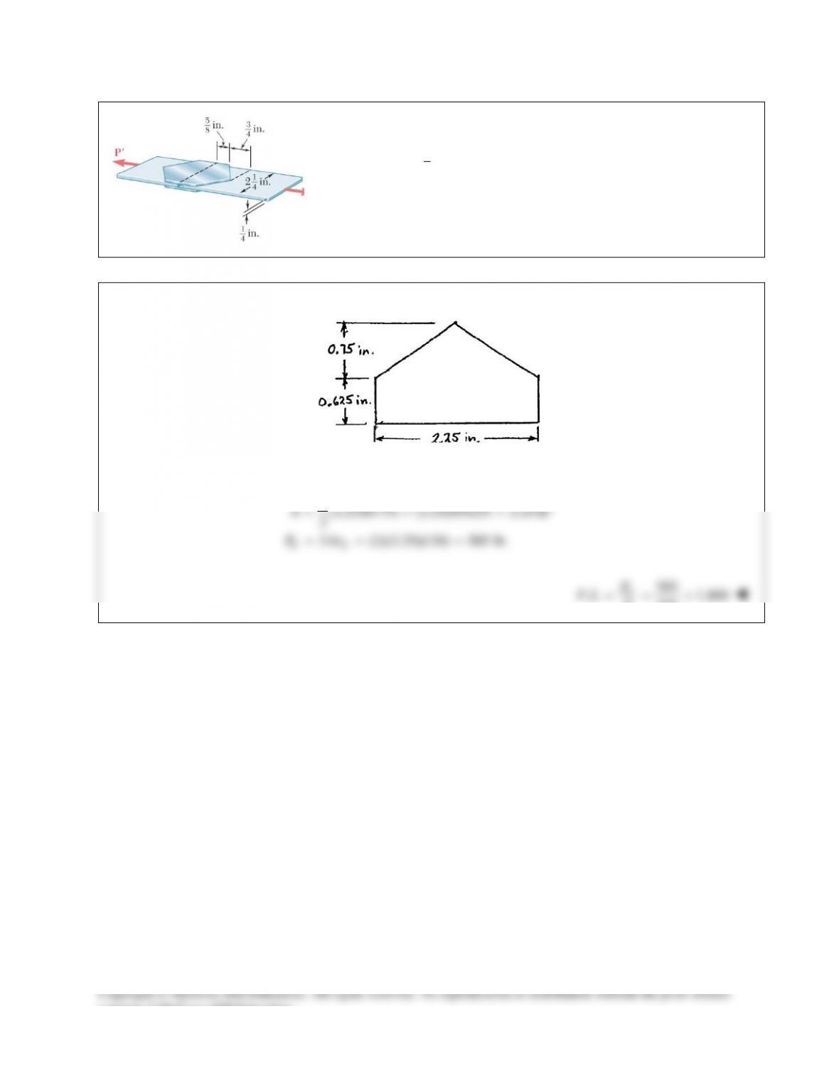
PROBLEM 8.38
Two plates, each
1
8
in. thick, are used to splice a plastic strip as shown.
Knowing that the ultimate shearing stress of the bonding between the
surface is 130 psi, determine the factor of safety with respect to shear
when
325 lb.P=
SOLUTION
Bond area: (See figure)
2
1(2.25)(0.75) (2.25)(0.625) 2.25 in
2
A= +=
2 (2)(2.25)(130) 585 lb.
UU
PA
τ
= = =
585
. . 1.800
325
U
P
FS P
= = =
consent of McGraw–Hill Education.
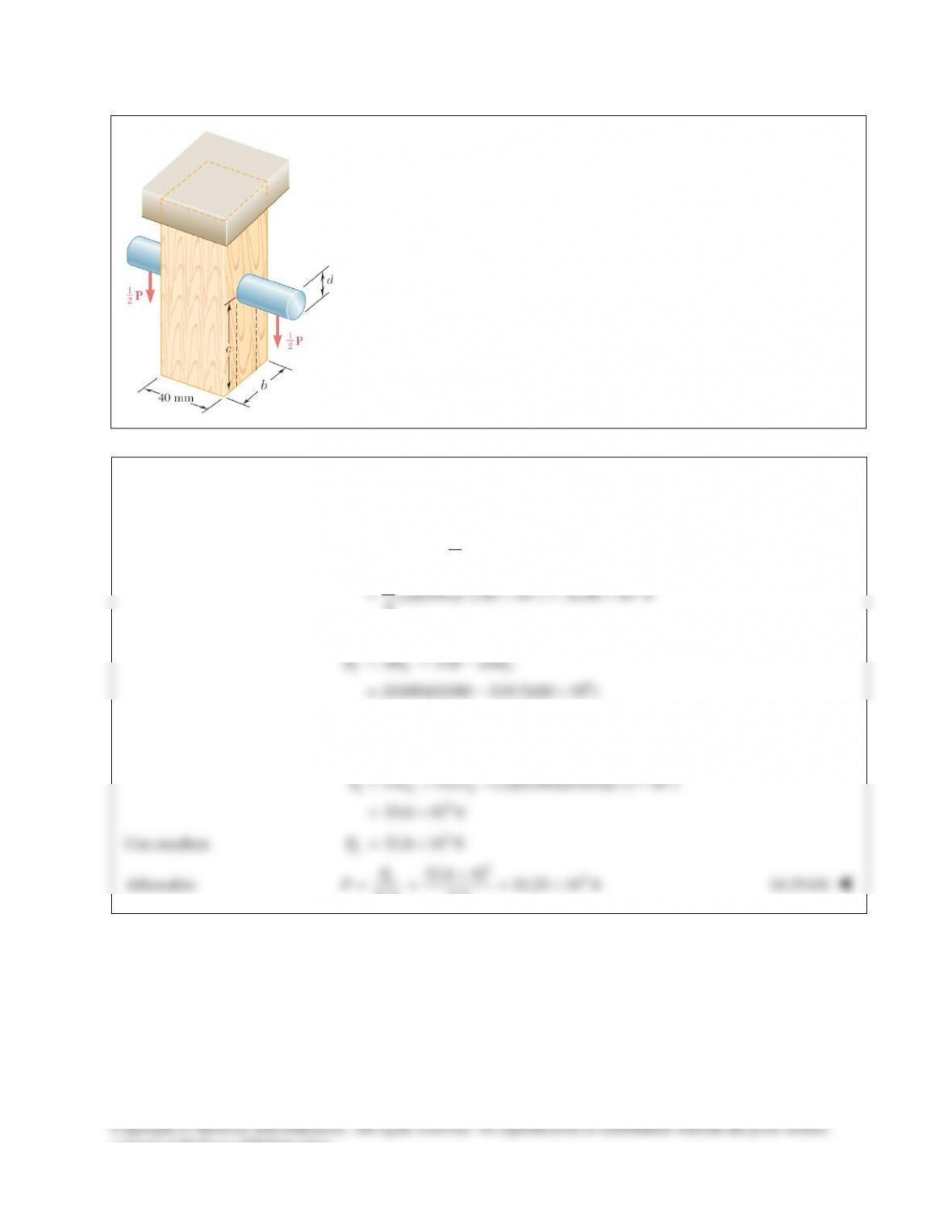
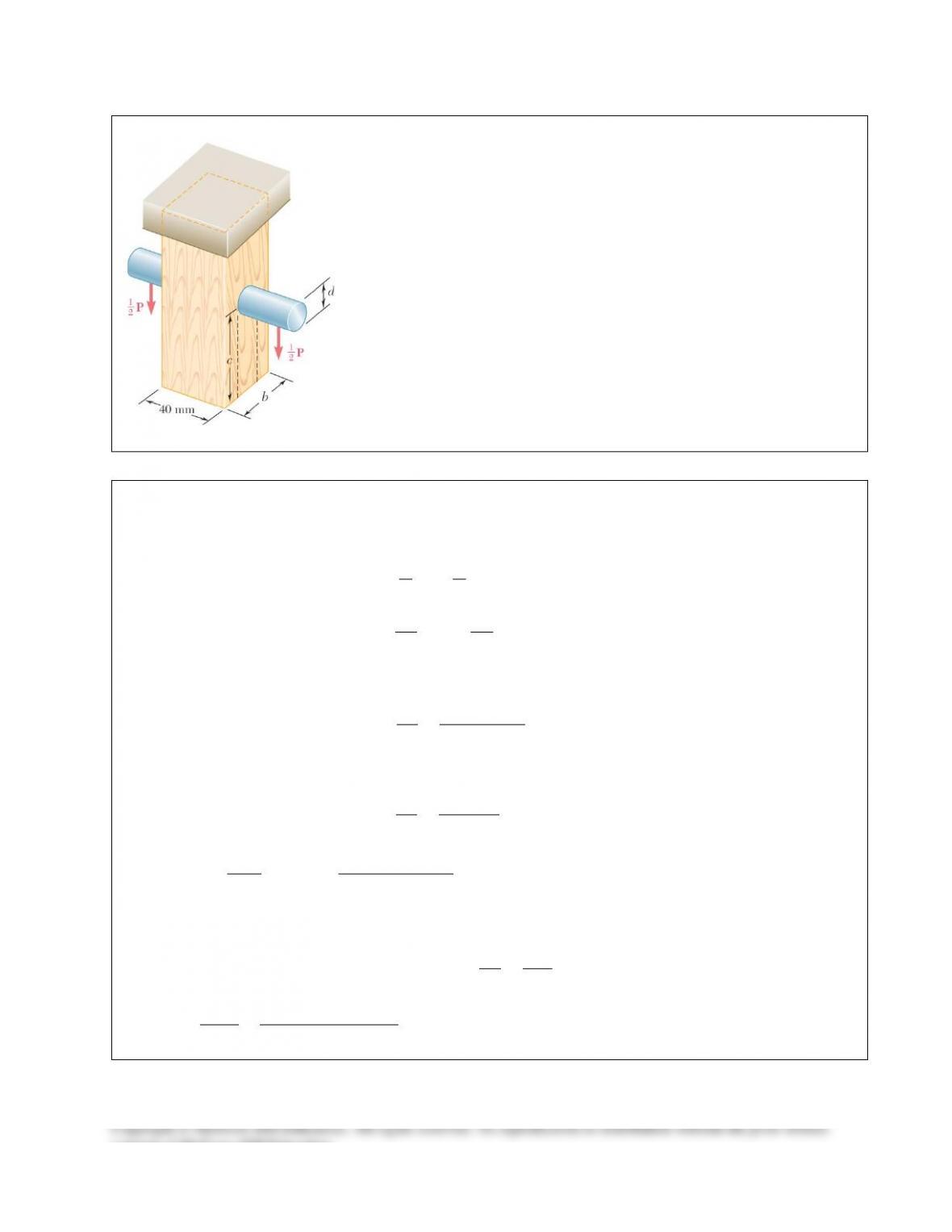
PROBLEM 8.39
A load P is supported as shown by a steel pin that has been inserted in a
short wooden member hanging from the ceiling. The ultimate strength of
the wood used is 60 MPa in tension and 7.5 MPa in shear, while the
ultimate strength of the steel is 145 MPa in shear. Knowing that
40 mm,b=
55 mm,c=
and
12 mm,d=
determine the load P if an
overall factor of safety of 3.2 is desired.
SOLUTION
Based on double shear in pin,
2
26 3
22
4
(2)(0.012) (145 10 ) 32.80 10 N
4
π
ττ
π
= =
= ×= ×
UU U
PA d
Based on tension in wood,
6
3
()
(0.040)(0.040 0.012)(60 10 )
67.2 10 N
UU U
P A wb d
σσ
= = −
= −×
= ×
Based on double shear in the wood,
6
3
2 2 (2)(0.040)(0.055)(7.5 10 )
33.0 10 N
ττ
= = = ×
= ×
UU U
P A wc
Use smallest
3
32.8 10 N= ×
U
P
Allowable:
33
32.8 10 10.25 10 N
. . 3.2
×
= = = ×
U
P
PFS
10.25 kN
consent of McGraw–Hill Education.
PROBLEM 8.40
For the support of Prob. 8.39, knowing that the diameter of the pin is d = 16
mm and that the magnitude of the load is P = 20 kN, determine (a) the
factor of safety for the pin, (b) the required values of b and c if the factor of
safety for the wooden member is the same as that found in part a for the
pin.
PROBLEM 8.39
A load P is supported as shown by a steel pin that has been inserted in a
short wooden member hanging from the ceiling. The ultimate strength of
the wood used is 60 MPa in tension and 7.5 MPa in shear, while the
ultimate strength of the steel is 145 MPa in shear. Knowing that b = 40
mm, c = 55 mm, and d = 12 mm, determine the load P if an overall factor
of safety of 3.2 is desired.
SOLUTION
3
20 kN 20 10 N= = ×P
(a) Pin:
2 2 62
(0.016) 201.06 10 m
44
Ad
ππ
−
= = = ×
Double shear:
22
U
U
PP
AA
ττ
= =
66 3
2 (2)(201.16 10 )(145 10 ) 58.336 10 N
UU
PA
τ
−
= = × ×= ×
3
3
58.336 10
. . 2.92
20 10
U
P
FS P
×
= = =
×
. . 2.92FS =
(b) Tension in wood:
3
58.336 10 N for same F.S.
U
P= ×
where 40 mm 0.040 m
()
UU
UPP w
A wb d
σ
= = = =
−
33
6
58.336 10
0.016 40.3 10 m
(0.040)(60 10 )
U
U
P
bdw
σ
×
=+=+ =×
×
40.3 mmb=
Shear in wood:
3
58.336 10 N for same F.S.
U
P= ×
Double shear: each area is
A wc=
22
τ
= =
UU
U
PP
A wc
33
6
58.336 10 97.2 10 m
2(2)(0.040)(7.5 10 )
U
U
P
cw
τ
−
×
= = = ×
×
97.2 mmc=
consent of McGraw–Hill Education.
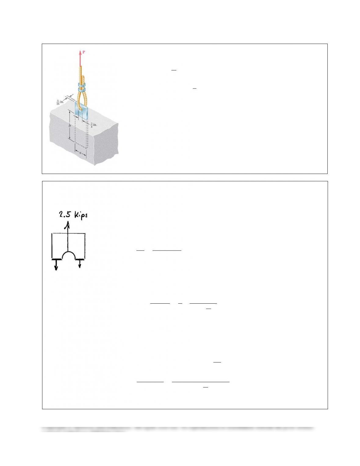
PROBLEM 8.41
A steel plate
5
16
in. thick is embedded in a horizontal concrete slab and is
used to anchor a high–strength vertical cable as shown. The diameter of
the hole in the plate is
3
4
in.,
the ultimate strength of the steel used is 36 ksi,
and the ultimate bonding stress between plate and concrete is 300 psi.
Knowing that a factor of safety of 3.60 is desired when P = 2.5 kips,
determine (a) the required width a of the plate, (b) the minimum depth b
to which a plate of that width should be embedded in the concrete slab.
(Neglect the normal stresses between the concrete and the lower end of
the plate.)
SOLUTION
Based on tension in plate:
()
()
..
σ
σ
= −
=
−
= =
UU
UU
A a dt
PA
P a dt
FS
PP
Solving for a,
( )
5
16
( . .) 3 (3.60)(2.5)
4(36)
U
FS P
ad t
σ
=+=+
(a)
1.550 in.
=a
Based on shear between plate and concrete slab,
perimeter depth 2( ) 0.300 ksi
U
A a tb
t
= ×=+ =
2 ( ) ..
U
UU U
P
P A a tb FS P
tt
==+=
Solving for b,
( )
5
16
( . .) (3.6)(2.5)
2( ) (2) 1.550 (0.300)
U
FS P
bat
t
= =
++
(b)
8.05 in.=b
consent of McGraw–Hill Education.
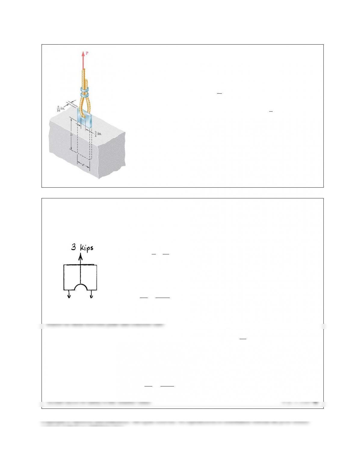
PROBLEM 8.42
Determine the factor of safety for the cable anchor in Prob. 8.41 when
3 kips,P=
knowing that
2 in.a=
and
7.5 in.b=
PROBLEM 8.41 A steel plate
5
16
in, thick is embedded in a horizontal
concrete slab and is used to anchor a high–strength vertical cable as
shown. The diameter of the hole in the plate is
3
4
in.,
the ultimate
strength of the steel used is 36 ksi, and the ultimate bonding stress
between plate and concrete is 300 psi. Knowing that a factor of safety of
3.60 is desired when
2.5 kips,P=
determine (a) the required width a of
the plate, (b) the minimum depth b to which a plate of that width should
be embedded in the concrete slab. (Neglect the normal stresses between
the concrete and the lower end of the plate.)
SOLUTION
Based on tension in plate:
2
()
35
2 0.3906 in
4 16
A a dt= −
=−=
(36)(0.3906) 14.06 kips
UU
PA
s
=
= =
14.06
. . 4.69
3
= = =
U
P
FS P
5
perimeter depth 2( ) 2 2 (7.5)
16
= × = += +
A a tb
2
34.69 in 0.300 ksi
U
A
τ
= =
(0.300)(34.69) 10.41kips
UU
PA
τ
= = =
10.41
. . 3.47
3
U
P
FS P
= = =
consent of McGraw–Hill Education.
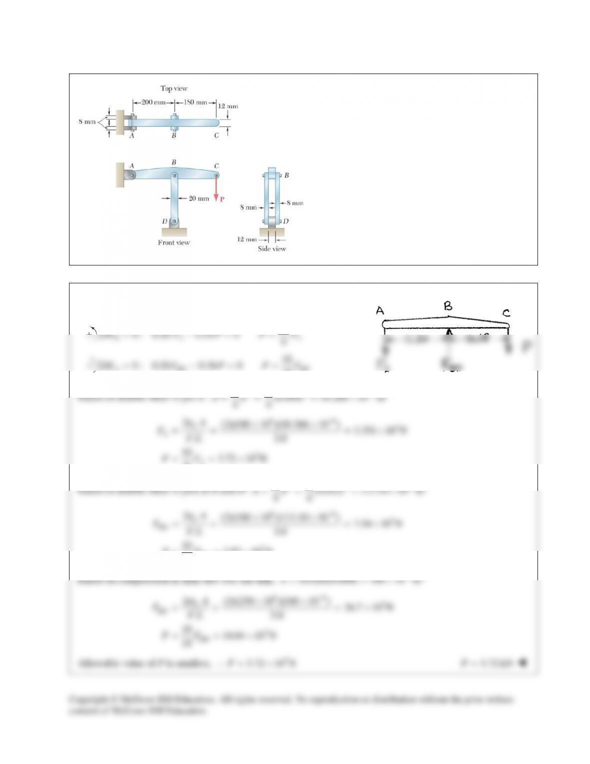
PROBLEM 8.43
In the structure shown, an 8–mm–diameter pin is
used at A, and 12–mm–diameter pins are used at B
and D. Knowing that the ultimate shearing stress is
100 MPa at all connections and that the ultimate
normal stress is 250 MPa in each of the two links
joining B and D, determine the allowable load P if
an overall factor of safety of 3.0 is desired.
SOLUTION
Statics: Use ABC as free body.
10
0 : 0.20 0.18 0 9
BA A
M F P PFΣ= − = =
10
0 : 0.20 0.38 0 19
A BD BD
M F P PFΣ= − = =
Based on double shear in pin A:
2 2 62
(0.008) 50.266 10 m
44
ππ
−
= = = ×Ad
663
3
2(2)(100 10 )(50.266 10 ) 3.351 10 N
. . 3.0
10 3.72 10 N
9
τ
−
××
= = = ×
= = ×
U
A
A
A
FFS
PF
Based on double shear in pins at B and D:
2 2 62
(0.012) 113.10 10 m
44
ππ
−
= = = ×Ad
66
3
3
2(2)(100 10 )(113.10 10 ) 7.54 10 N
. . 3.0
10 3.97 10 N
19
U
BD
BD
A
FFS
PF
τ
−
××
= = = ×
= = ×
Based on compression in links BD: For one link,
62
(0.020)(0.008) 160 10 m
−
= = ×A
66 3
3
2 (2)(250 10 )(160 10 ) 26.7 10 N
. . 3.0
10 14.04 10 N
19
σ
−
××
= = = ×
= = ×
U
BD
BD
A
FFS
PF
Allowable value of P is smallest, ∴
3
3.72 10 N= ×P
3.72 kN=P
Copyright © McGraw–Hill Education. All rights reserved. No reproduction or distribution without the prior written
consent of McGraw–Hill Education.
PROBLEM 8.45
Link AC is made of a steel with a 65–ksi ultimate normal stress and has
a
11
42
×
–in. uniform rectangular cross section. It is connected to a
support at A and to member BCD at C by
3
8
–in.–diameter pins, while
member BCD is connected to its support at B by a
5
16
–in.–diameter pin;
all of the pins are made of a steel with a 25–ksi ultimate shearing stress
and are in single shear. Knowing that a factor of safety of 3.25 is
desired, determine the largest load P that can be applied at D. Note that
link AC is not reinforced around the pin holes.
SOLUTION
Use free body BCD.
8
0 : (6) 10 0
10
B AC
M FP
= −=
0.48
AC
PF=
(1)
6
0: 0
10
x x AC
F BFΣ= − =
61.25
10
= =
x AC
BF P
0: 6 4 0= − −=
Cy
M BP
22
i.e.
33
yy
B P BP
=−=
2
22 2
2
1.25 1.41667 0.70588
3
= += + = =
xy
B BB P P P B
(2)
Shear in pins at A and C.
2
2
pin 25 3 0.84959 kips
. . 4 3.25 4 8
U
AC
FA d
FS
τp p
τ
= = = =
Tension on net section of A and C.
net net 65 1 1 3 0.625 kips
. . 3.25 4 2 8
U
AC
FA A
FS
s
s
= = = −=
Smaller value of FAC is 0.625 kips.
From (1),
(0.48)(0.625) 0.300 kipsP= =
Shear in pin at B.
2
2
pin 25 5 0.58999 kips
. . 4 3.25 4 16
U
BA d
FS
τp p
τ
= = = =
From (2),
(0.70588)(0.58999) 0.416 kipsP= =
Allowable value of P is the smaller value.
0.300 kipsP=
or
300 lbP=
consent of McGraw–Hill Education.