PROBLEM 9.30 (Continued)
C to D:
3
60 10
100 mm 0.100 m
= −×
= =
A
PR
L
PROBLEM 9.31
Solve Prob. 9.30, assuming that rod AC is made of brass and
rod CE is made of steel.
PROBLEM 9.30 Two cylindrical rods, one of steel and the
other of brass, are joined at C and restrained by rigid supports at A
and E. For the loading shown and knowing that
200
s
E=
GPa
and
105 GPa,
b
E=
determine (a) the reactions at A and E, (b) the
deflection of point C.
SOLUTION
A to C:
9
2 3 2 32
6
105 10 Pa
(40) 1.25664 10 mm 1.25664 10 m
4
131.947 10 N
E
A
EA
π
−
= ×
==×=×
= ×
C to E:
9
2 2 62
6
200 10 Pa
(30) 706.86 mm 706.86 10 m
4
141.372 10 N
E
A
EA
π
−
= ×
= = = ×
= ×
A to B:
6
9
180 mm 0.180 m
(0.180)
131.947 10
1.36418 10
δ
−
=
= =
= = ×
= ×
A
A
AB
A
PR
L
R
PL
EA
R
B to C:
3
3
6
12 6
60 10
120 mm 0.120 m
( 60 10 )(0.120)
131.947 10
909.456 10 54.567 10
A
A
BC
A
PR
L
R
PL
EA
R
δ
−−
= −×
= =
−×
= = ×
= × −×
C to D:
3
3
6
12 6
60 10
100 mm 0.100 m
( 60 10 )(0.100)
141.372 10
707.354 10 42.441 10
δ
−−
= −×
= =
−×
= = ×
= × −×
A
A
CD
A
PR
L
R
PL
EA
R
consent of McGraw–Hill Education.
PROBLEM 9.31 (Continued)
D to E:
3
3
6
12 6
100 10
100 mm 0.100 m
( 100 10 )(0.100)
141.372 10
707.354 10 70.735 10
δ
−−
=−×
= =
−×
= = ×
= × −×
A
A
DE
A
PR
L
R
PL
EA
R
A to E:
96
3.68834 10 167.743 10
δδδδδ
−−
=+++
= ×− ×
AE AB BC CD DE
A
R
Since point E cannot move relative to A,
0
AE
δ
=
(a)
96 3
3.68834 10 167.743 10 0 45.479 10 N
−−
× − ×= = ×
AA
RR
45.5 kN
= ←
A
R
3 33 3
100 10 45.479 10 100 10 54.521 10
EA
RR=−×= ×−×=− ×
54.5 kN= ←
E
R
(b)
96
2.27364 10 54.567 10
δδ δ
−−
=+= × − ×
C AB BC A
R
93 6
6
(2.27364 10 )(45.479 10 ) 54.567 10
48.8 10 m
−−
−
= × ×− ×
= ×
48.8 m
C
δm
= →
consent of McGraw–Hill Education.
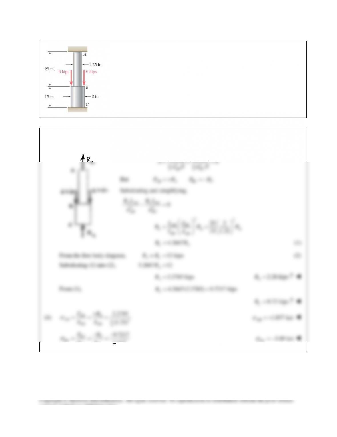
PROBLEM 9.32
A polystyrene rod consisting of two cylindrical portions AB and BC is restrained at
both ends and supports two 6-kip loads as shown. Knowing that
6
0.45 10 psi,= ×E
determine (a) the reactions at A and C, (b) the normal stress in each portion of
the rod.
SOLUTION
(a) We express that the elongation of the rod is zero.
22
44
0
BC BC
AB AB
AB BC
PL
PL
dE dE
ππ
d
=+=
But
AB A BC C
PRPR=+=−
Substituting and simplifying,
22
0
C BC
A AB
AB BC
RL
RL
dd
−=
22
25 2
15 1.25
= =
BC
AB
C AA
BC AB
d
L
R RR
Ld
4.2667
CA
RR
=
(1)
From the free body diagram,
12 kips
AC
RR+=
(2)
Substituting (1) into (2),
5.2667 12=
A
R
2.2785 kips
A
R=
2.28 kips
A
R= ↑
From (1),
4.2667(2.2785) 9.7217 kips
C
R= =
9.72 kips
C
R= ↑
(b)
2
4
2.2785
(1.25)
π
σ
+
= = =
AB A
AB AB AB
PR
AA
1.857 ksi
AB
σ
= +
2
4
9.7217
(2)
BC C
BC BC BC
PR
AA
π
σ
−−
= = =
3.09 ksi
BC
σ
= −
consent of McGraw–Hill Education.
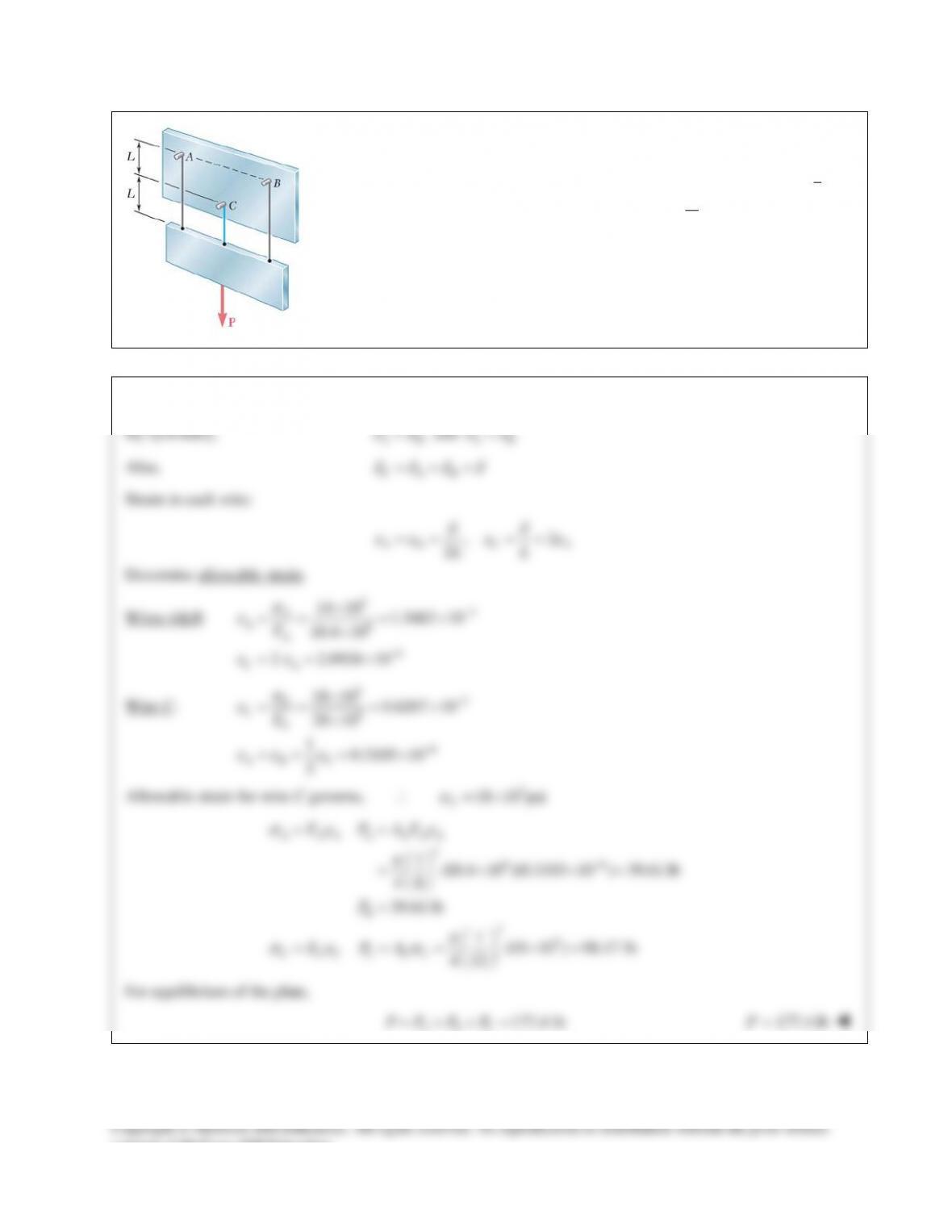
PROBLEM 9.33
Three wires are used to suspend the plate shown. Aluminum wires of
1
8-in.
diameter are used at A and B while a steel wire of
1
12 -in.
diameter is used at
C. Knowing that the allowable stress for aluminum
6
( 10.4 10 psi)
a
E= ×
is
14 ksi and that the allowable stress for steel
6
( 29 10 psi)
s
E= ×
is 18 ksi,
determine the maximum load P that can be applied.
SOLUTION
By symmetry,
,
AB
PP
=
and
AB
δδ
=
Also,
CAB
δδδδ
===
Strain in each wire:
,2
2
AB C A
LL
δδ
εε ε ε
= = = =
Determine allowable strain.
Wires A&B:
33
6
4
14 10 1.3462 10
10.4 10
2 2.6924 10
A
AA
CA
E
σ
ε
εε
−
−
×
= = = ×
×
= = ×
Wire C:
33
6
6
18 10 0.6207 10
29 10
10.3103 10
2
C
CC
AB C
E
σ
ε
εε ε
−
−
×
= = = ×
×
= = = ×
Allowable strain for wire C governs, ∴
3
18 10 psi
C
σ
= ×
266
23
1(10.4 10 )(0.3103 10 ) 39.61 lb
48
39.61 lb
1(18 10 ) 98.17 lb
4 12
σε ε
π
π
σε σ
−
= =
= × ×=
=
= = = ×=
A AA A A AA
B
C CC C C C
E P AE
P
E PA
For equilibrium of the plate,
177.4 lb=++=
ABC
PPPP
177.4 lb=P
consent of McGraw–Hill Education.
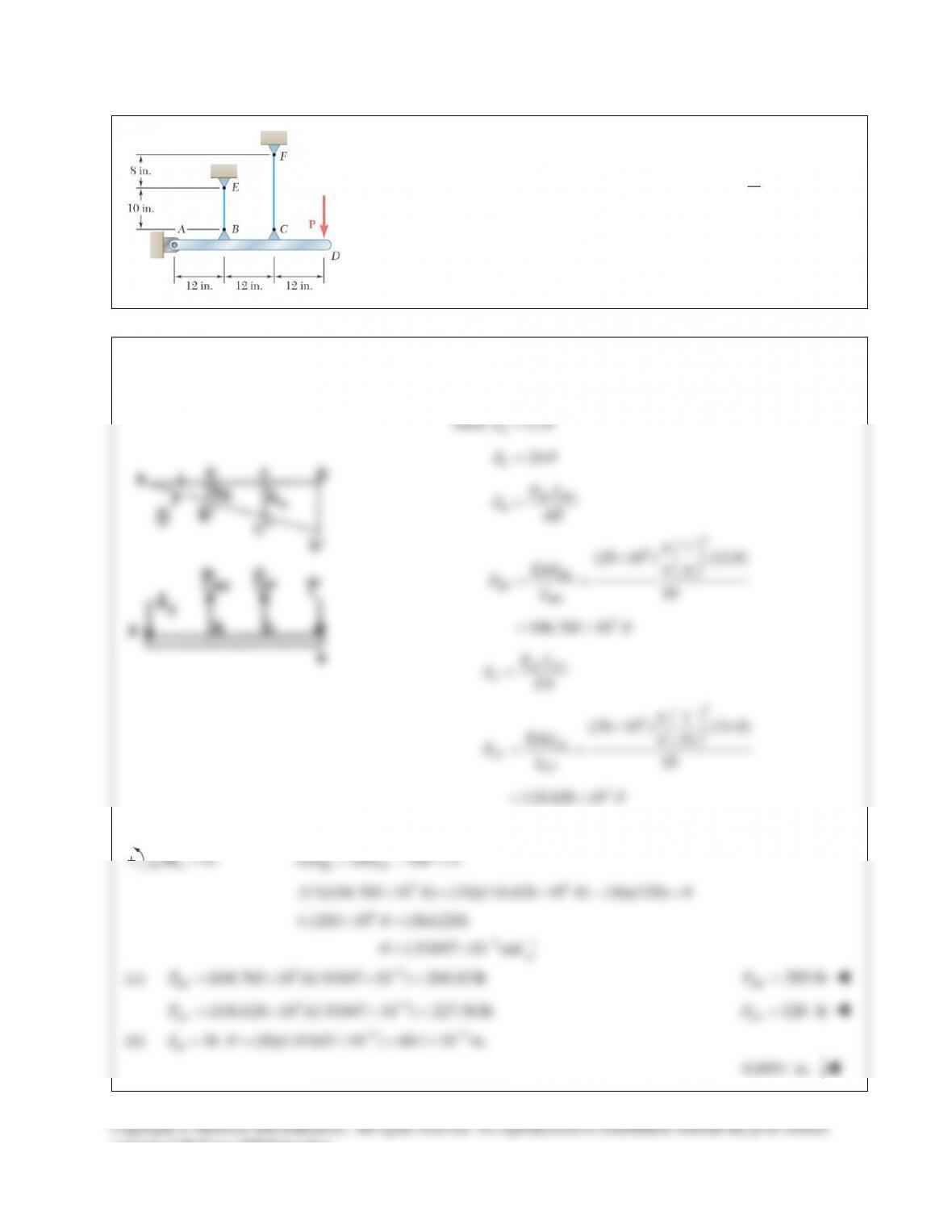
PROBLEM 9.34
The rigid bar AD is supported by two steel wires of
1
16
–in. diameter
(E = 29 × 106 psi) and a pin and bracket at A. Knowing that the
wires were initially taut, determine (a) the additional tension in each
wire when a 220–lb load P is applied at D, (b) the corresponding
deflection of point D.
SOLUTION
Let
θ
be the notation of bar ABCD.
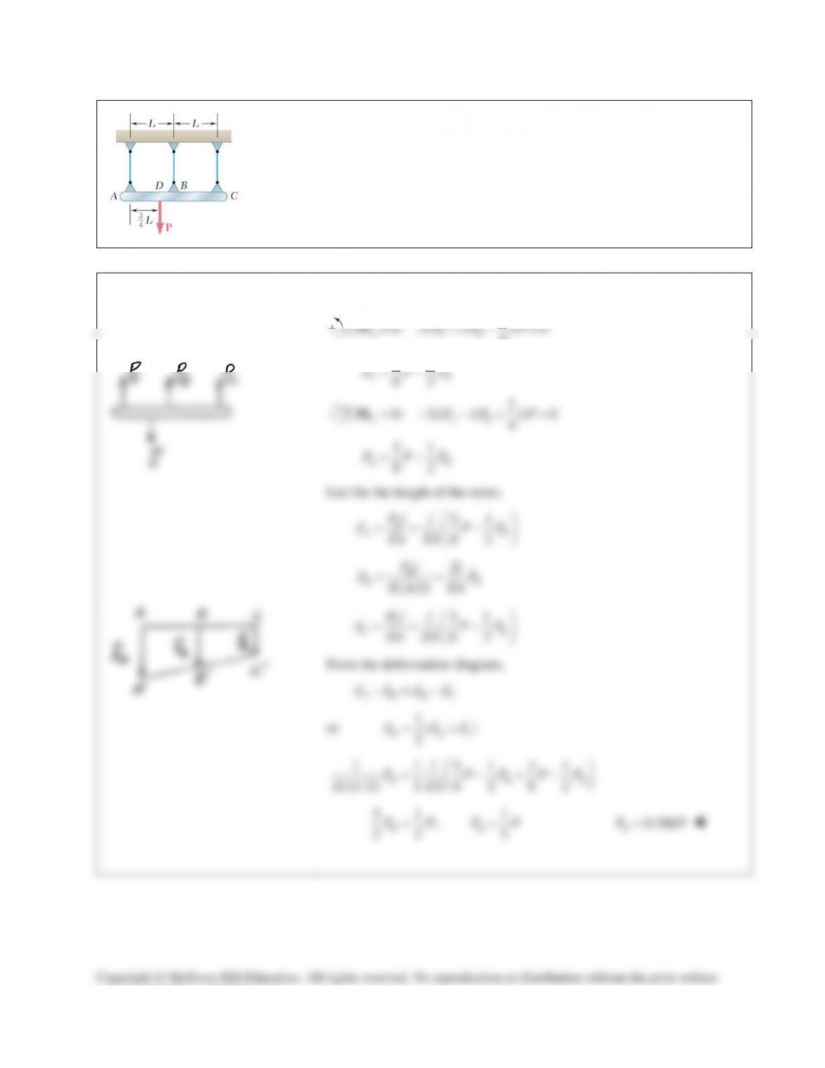
PROBLEM 9.35
The rigid bar ABC is suspended from three wires of the same material. The cross–
sectional area of the wire at B is equal to half of the cross–sectional area of the
wires at A and C. Determine the tension in each wire caused by the load P shown.
SOLUTION
3
0: 2 0
4
∑= +− =
A CB
LP LP LPM
31
82
CB
P PP= −
5
0: 2 0
4
∑=− −+ =
C AB
LP LP LPM
51
82
AB
P PP= −
Let l be the length of the wires.
51
82
= = −
A
AB
Pl lPP
EA EA
δ
2
( /2)
= =
B
BB
Pl lP
E A EA
δ
31
82
= = −
C
CB
Pl lPP
EA EA
δ
From the deformation diagram,
AB BC
δδδδ
−=−
or
1()
2
B Ac
δ δδ
= +
1 51 31
( / 2) 2 8 2 8 2
B BB
ll
P PP PP
E A EA
= − +−
51 1
;
22 5
BB
PP PP= =
0.200
B
PP=
Copyright © McGraw–Hill Education. All rights reserved. No reproduction or distribution without the prior written
consent of McGraw–Hill Education.
PROBLEM 9.35 (Continued)
5 1 21
8 2 5 40
A
P
PP P
=−=
0.525
A
PP
=
3 1 11
8 2 5 40
C
P
PP P
=−=
0.275
=
C
PP
Check:
1.000 Ok++=
ABC
PPP P
consent of McGraw–Hill Education.
PROBLEM 9.36
The rigid bar ABCD is suspended from four identical wires. Determine the
tension in each wire caused by the load P shown.
SOLUTION
Deformations Let
θ
be the rotation of bar ABCD and
,,
ABC
δδδ
and
D
δ
be the deformations of wires A, B,
C, and D.
From geometry,
BA
L
δδ
θ
−
=
BA
L
δδ θ
= +
22
CA BA
L
δδ θδδ
=+=−
(1)
332
DA B A
L
δδ θδ δ
=+=−
(2)
Since all wires are identical, the forces in the wires are proportional to the deformations.
2
C BA
T TT= −
(1′)
32
DBA
TTT= −
(2′)
SOLUTION Continued
Use bar ABCD as a free body.
0: 2 0
C ABD
M LT LT LTΣ= − − + =
(3)
0: 0
y ABCD
F TTTTPΣ = + + + −=
(4)
Substituting (2′) into (3) and dividing by L,
420 2
AB B A
TT TT−+ = =
(3′)
Substituting (1′), (2′), and (3′) into (4),
234 0
AAAA
TTTTP+++−=
10
A
TP=
1
10
A
TP=
1
2 (2) 10
BA
TT P
= =
1
5
B
TP=
11
(2) 5 10
C
T PP
= −
3
10
C
TP=
11
(3) (2)
5 10
D
TP P
= −
2
5
D
TP=
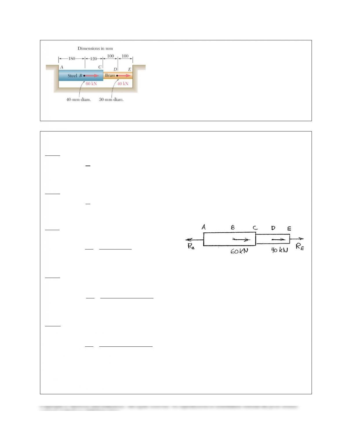
PROBLEM 9.31
Solve Prob. 9.30, assuming that rod AC is made of brass and
rod CE is made of steel.
PROBLEM 9.30 Two cylindrical rods, one of steel and the
other of brass, are joined at C and restrained by rigid supports at A
and E. For the loading shown and knowing that
200
s
E=
GPa
and
105 GPa,
b
E=
determine (a) the reactions at A and E, (b) the
deflection of point C.
SOLUTION
A to C:
9
2 3 2 32
6
105 10 Pa
(40) 1.25664 10 mm 1.25664 10 m
4
131.947 10 N
E
A
EA
π
−
= ×
==×=×
= ×
C to E:
9
2 2 62
6
200 10 Pa
(30) 706.86 mm 706.86 10 m
4
141.372 10 N
E
A
EA
π
−
= ×
= = = ×
= ×
A to B:
6
9
180 mm 0.180 m
(0.180)
131.947 10
1.36418 10
δ
−
=
= =
= = ×
= ×
A
A
AB
A
PR
L
R
PL
EA
R
B to C:
3
3
6
12 6
60 10
120 mm 0.120 m
( 60 10 )(0.120)
131.947 10
909.456 10 54.567 10
A
A
BC
A
PR
L
R
PL
EA
R
δ
−−
= −×
= =
−×
= = ×
= × −×
C to D:
3
3
6
12 6
60 10
100 mm 0.100 m
( 60 10 )(0.100)
141.372 10
707.354 10 42.441 10
δ
−−
= −×
= =
−×
= = ×
= × −×
A
A
CD
A
PR
L
R
PL
EA
R
consent of McGraw–Hill Education.
PROBLEM 9.31 (Continued)
D to E:
3
3
6
12 6
100 10
100 mm 0.100 m
( 100 10 )(0.100)
141.372 10
707.354 10 70.735 10
δ
−−
=−×
= =
−×
= = ×
= × −×
A
A
DE
A
PR
L
R
PL
EA
R
A to E:
96
3.68834 10 167.743 10
δδδδδ
−−
=+++
= ×− ×
AE AB BC CD DE
A
R
Since point E cannot move relative to A,
0
AE
δ
=
(a)
96 3
3.68834 10 167.743 10 0 45.479 10 N
−−
× − ×= = ×
AA
RR
45.5 kN
= ←
A
R
3 33 3
100 10 45.479 10 100 10 54.521 10
EA
RR=−×= ×−×=− ×
54.5 kN= ←
E
R
(b)
96
2.27364 10 54.567 10
δδ δ
−−
=+= × − ×
C AB BC A
R
93 6
6
(2.27364 10 )(45.479 10 ) 54.567 10
48.8 10 m
−−
−
= × ×− ×
= ×
48.8 m
C
δm
= →
consent of McGraw–Hill Education.
PROBLEM 9.32
A polystyrene rod consisting of two cylindrical portions AB and BC is restrained at
both ends and supports two 6-kip loads as shown. Knowing that
6
0.45 10 psi,= ×E
determine (a) the reactions at A and C, (b) the normal stress in each portion of
the rod.
SOLUTION
(a) We express that the elongation of the rod is zero.
22
44
0
BC BC
AB AB
AB BC
PL
PL
dE dE
ππ
d
=+=
But
AB A BC C
PRPR=+=−
Substituting and simplifying,
22
0
C BC
A AB
AB BC
RL
RL
dd
−=
22
25 2
15 1.25
= =
BC
AB
C AA
BC AB
d
L
R RR
Ld
4.2667
CA
RR
=
(1)
From the free body diagram,
12 kips
AC
RR+=
(2)
Substituting (1) into (2),
5.2667 12=
A
R
2.2785 kips
A
R=
2.28 kips
A
R= ↑
From (1),
4.2667(2.2785) 9.7217 kips
C
R= =
9.72 kips
C
R= ↑
(b)
2
4
2.2785
(1.25)
π
σ
+
= = =
AB A
AB AB AB
PR
AA
1.857 ksi
AB
σ
= +
2
4
9.7217
(2)
BC C
BC BC BC
PR
AA
π
σ
−−
= = =
3.09 ksi
BC
σ
= −
consent of McGraw–Hill Education.
PROBLEM 9.33
Three wires are used to suspend the plate shown. Aluminum wires of
1
8-in.
diameter are used at A and B while a steel wire of
1
12 -in.
diameter is used at
C. Knowing that the allowable stress for aluminum
6
( 10.4 10 psi)
a
E= ×
is
14 ksi and that the allowable stress for steel
6
( 29 10 psi)
s
E= ×
is 18 ksi,
determine the maximum load P that can be applied.
SOLUTION
By symmetry,
,
AB
PP
=
and
AB
δδ
=
Also,
CAB
δδδδ
===
Strain in each wire:
,2
2
AB C A
LL
δδ
εε ε ε
= = = =
Determine allowable strain.
Wires A&B:
33
6
4
14 10 1.3462 10
10.4 10
2 2.6924 10
A
AA
CA
E
σ
ε
εε
−
−
×
= = = ×
×
= = ×
Wire C:
33
6
6
18 10 0.6207 10
29 10
10.3103 10
2
C
CC
AB C
E
σ
ε
εε ε
−
−
×
= = = ×
×
= = = ×
Allowable strain for wire C governs, ∴
3
18 10 psi
C
σ
= ×
266
23
1(10.4 10 )(0.3103 10 ) 39.61 lb
48
39.61 lb
1(18 10 ) 98.17 lb
4 12
σε ε
π
π
σε σ
−
= =
= × ×=
=
= = = ×=
A AA A A AA
B
C CC C C C
E P AE
P
E PA
For equilibrium of the plate,
177.4 lb=++=
ABC
PPPP
177.4 lb=P
consent of McGraw–Hill Education.
PROBLEM 9.34
The rigid bar AD is supported by two steel wires of
1
16
–in. diameter
(E = 29 × 106 psi) and a pin and bracket at A. Knowing that the
wires were initially taut, determine (a) the additional tension in each
wire when a 220–lb load P is applied at D, (b) the corresponding
deflection of point D.
SOLUTION
Let
θ
be the notation of bar ABCD.
PROBLEM 9.35
The rigid bar ABC is suspended from three wires of the same material. The cross–
sectional area of the wire at B is equal to half of the cross–sectional area of the
wires at A and C. Determine the tension in each wire caused by the load P shown.
SOLUTION
3
0: 2 0
4
∑= +− =
A CB
LP LP LPM
31
82
CB
P PP= −
5
0: 2 0
4
∑=− −+ =
C AB
LP LP LPM
51
82
AB
P PP= −
Let l be the length of the wires.
51
82
= = −
A
AB
Pl lPP
EA EA
δ
2
( /2)
= =
B
BB
Pl lP
E A EA
δ
31
82
= = −
C
CB
Pl lPP
EA EA
δ
From the deformation diagram,
AB BC
δδδδ
−=−
or
1()
2
B Ac
δ δδ
= +
1 51 31
( / 2) 2 8 2 8 2
B BB
ll
P PP PP
E A EA
= − +−
51 1
;
22 5
BB
PP PP= =
0.200
B
PP=
Copyright © McGraw–Hill Education. All rights reserved. No reproduction or distribution without the prior written
consent of McGraw–Hill Education.
PROBLEM 9.35 (Continued)
5 1 21
8 2 5 40
A
P
PP P
=−=
0.525
A
PP
=
3 1 11
8 2 5 40
C
P
PP P
=−=
0.275
=
C
PP
Check:
1.000 Ok++=
ABC
PPP P
consent of McGraw–Hill Education.
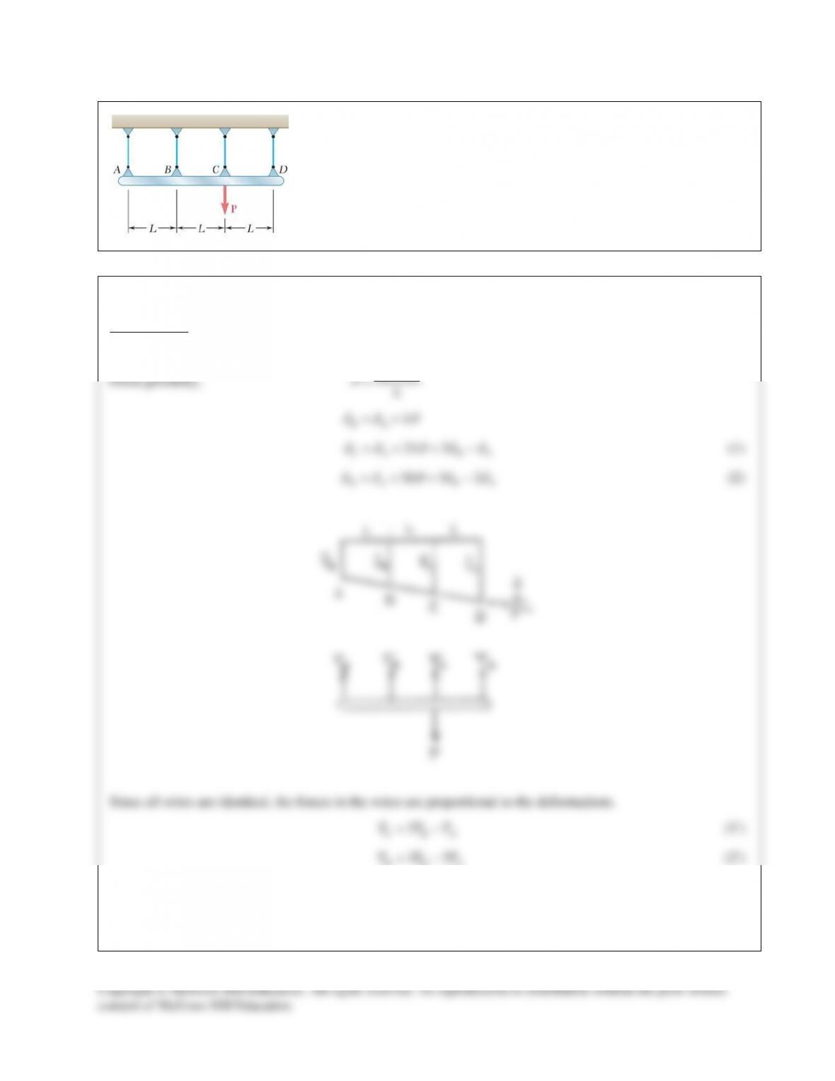
PROBLEM 9.36
The rigid bar ABCD is suspended from four identical wires. Determine the
tension in each wire caused by the load P shown.
SOLUTION
Deformations Let
θ
be the rotation of bar ABCD and
,,
ABC
δδδ
and
D
δ
be the deformations of wires A, B,
C, and D.
From geometry,
BA
L
δδ
θ
−
=
BA
L
δδ θ
= +
22
CA BA
L
δδ θδδ
=+=−
(1)
332
DA B A
L
δδ θδ δ
=+=−
(2)
Since all wires are identical, the forces in the wires are proportional to the deformations.
2
C BA
T TT= −
(1′)
32
DBA
TTT= −
(2′)
SOLUTION Continued
Use bar ABCD as a free body.
0: 2 0
C ABD
M LT LT LTΣ= − − + =
(3)
0: 0
y ABCD
F TTTTPΣ = + + + −=
(4)
Substituting (2′) into (3) and dividing by L,
420 2
AB B A
TT TT−+ = =
(3′)
Substituting (1′), (2′), and (3′) into (4),
234 0
AAAA
TTTTP+++−=
10
A
TP=
1
10
A
TP=
1
2 (2) 10
BA
TT P
= =
1
5
B
TP=
11
(2) 5 10
C
T PP
= −
3
10
C
TP=
11
(3) (2)
5 10
D
TP P
= −
2
5
D
TP=