consent of McGraw–Hill Education.
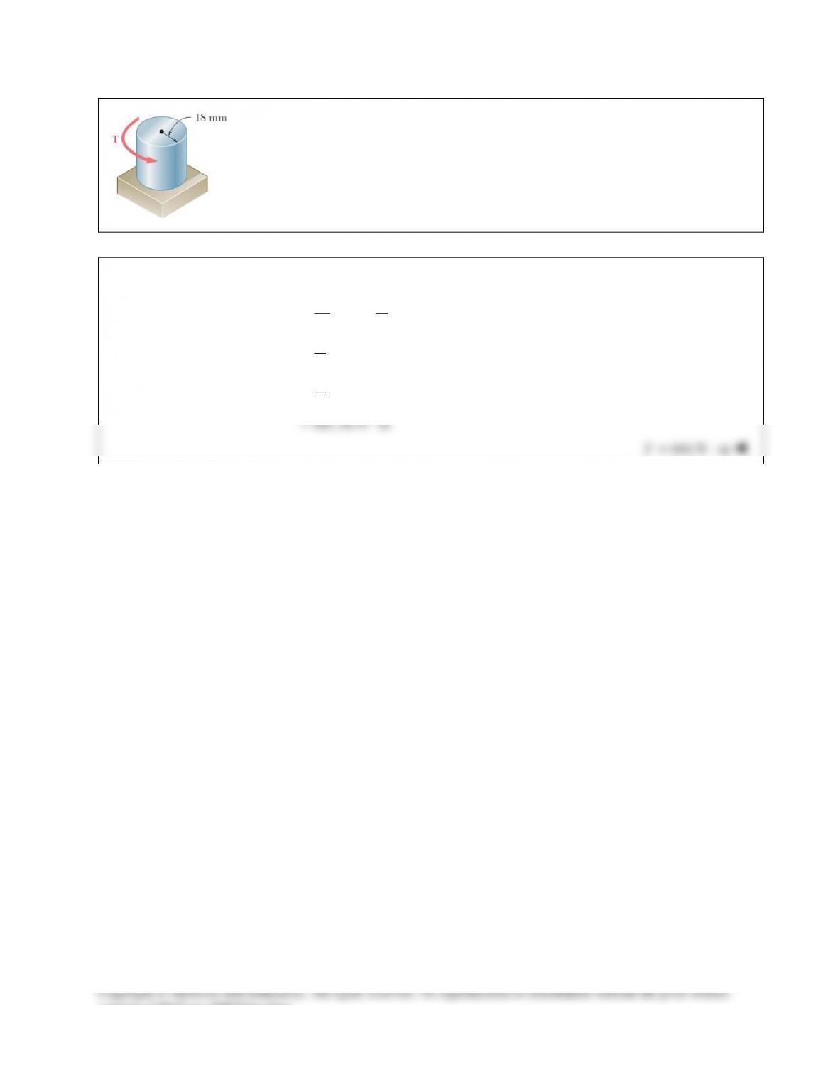
PROBLEM 10.1
Determine the torque T that causes a maximum shearing stress of 70 MPa in the steel
cylindrical shaft shown.
SOLUTION
4
max
3max
36
;2
2
(0.018 m) (70 10 Pa)
2
641.26 N m
π
τ
πτ
π
= =
=
= ×
= ⋅
Tc Jc
J
Tc
641 N m= ⋅
T
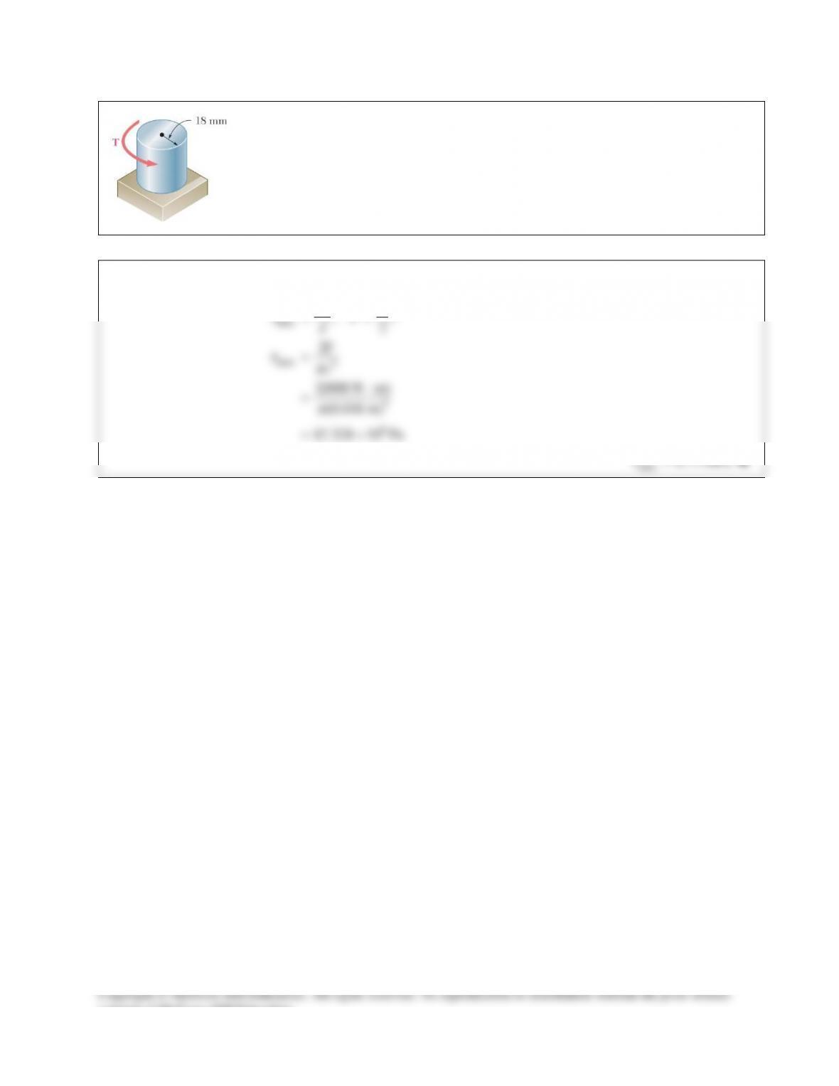
PROBLEM 10.2
For the cylindrical shaft shown, determine the maximum shearing stress caused by
a torque of magnitude T = 800 N ⋅ m.
SOLUTION
4
max
max 3
3
6
;2
2
2(800 N m)
(0.018 m)
87.328 10 Pa
π
τ
τπ
π
= =
=
⋅
=
= ×
Tc Jc
J
T
c
max 87.3 MPa
τ
=
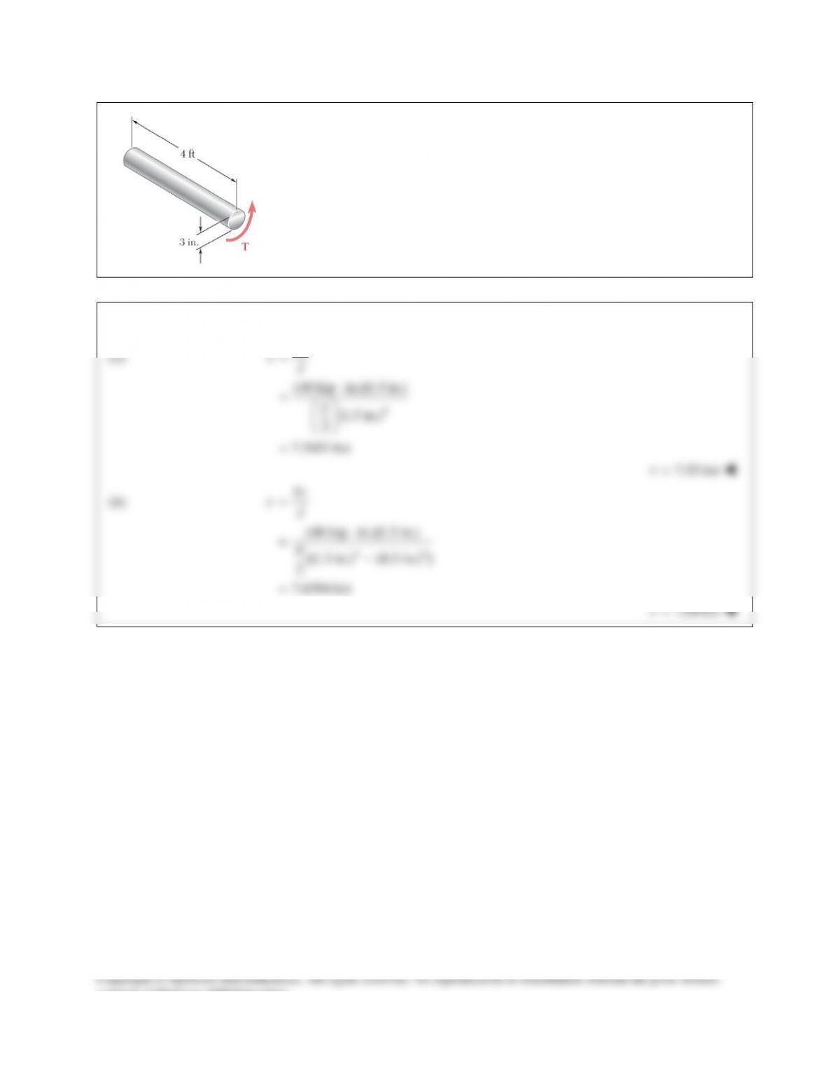
PROBLEM 10.3
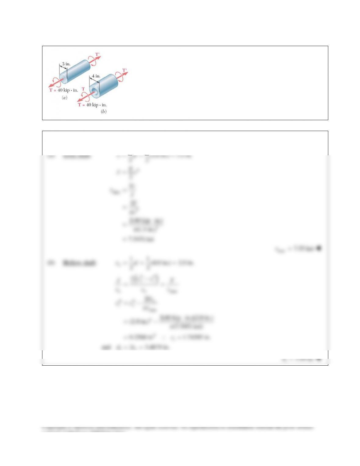
(a) Determine the maximum shearing stress caused by a 40-kip ⋅ in. torque T in
the 3–in.–diameter solid aluminum shaft shown. (b) Solve part a, assuming that
the solid shaft has been replaced by a hollow shaft of the same outer diameter
and of 1-in. inner diameter.
SOLUTION
(a)
4
(40 kip in.)(1.5 in.)
(1.5 in.)
2
7.5451 ksi
τ
p
=
⋅
=
=
Tc
J
consent of McGraw–Hill Education.
PROBLEM 10.4
(a) Determine the torque that can be applied to a solid shaft of 20–mm diameter without exceeding an
allowable shearing stress of 80 MPa. (b) Solve Part a, assuming that the solid shaft has been replaced by a
hollow shaft of the same cross–sectional area and with an inner diameter equal to half of its own outer
diameter.
SOLUTION
(a) Solid shaft:
4 4 94
11
(0.020) 0.010 m
22
(0.10) 15.7080 10 m
22
cd
Jc
ππ
−
= = =
=−=×
96
max
(15.7080 10 )(80 10 ) 125.664
0.010
J
Tc
τ
−
××
= = =
125.7 N mT= ⋅
(b) Hollow shaft: Same area as solid shaft.
()
()
2
22 2 2 2
21 2 2 2
2
12
4 4 4 4 94
21
13
24
22
(0.010) 0.0115470 m
33
10.0057735 m
2
(0.0115470 0.0057735 ) 26.180 10 m
22
A cc c c c c
cc
cc
J cc
π π ππ
ππ
−
= −= − = =
= = =
= =
= −= − = ×
69
max
2
(80 10 )(26.180 10 ) 181.38
0.0115470
J
Tc
τ
−
××
= = =
181.4 N mT= ⋅
consent of McGraw–Hill Education.
PROBLEM 10.5
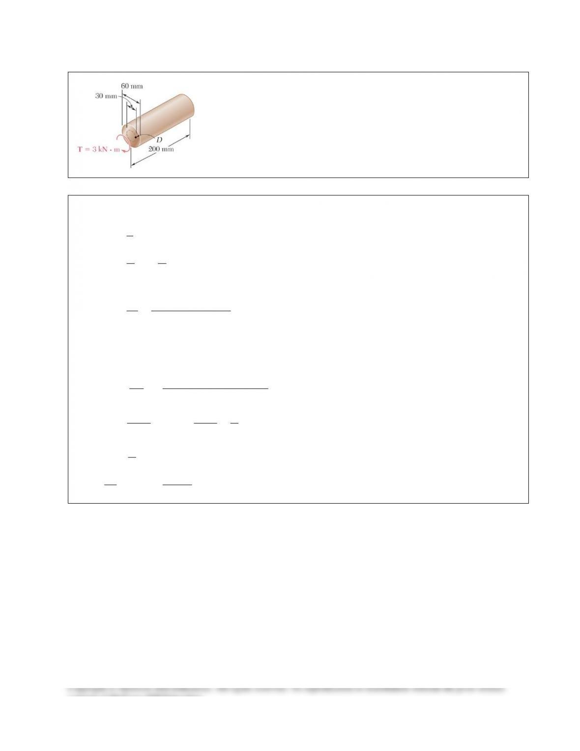
A torque
3 kN m
T= ⋅
is applied to the solid bronze cylinder shown.
Determine (a) the maximum shearing stress, (b) the shearing stress at point D
which lies on a 15–mm–radius circle drawn on the end of the cylinder, (c) the
percent of the torque carried by the portion of the cylinder within the 15–mm
radius.
SOLUTION
(a)
3
4 34 6 4
3
33 6
6
130 mm 30 10 m
2
(30 10 ) 1.27235 10 m
22
3 kN 3 10 N
(3 10 )(30 10 ) 70.736 10 Pa
1.27235 10
m
cd
Jc
T
Tc
J
ππ
τ
−
−−
−
−
= = = ×
==×= ×
= = ×
××
= = = ×
×
70.7 MPa
m
τ
=
(b)
3
15 mm 15 10 m
D
ρ
−
= = ×
36
3
(15 10 )(70.736 10 )
(30 10 )
D
D
c
ρ
ττ
−−
−
××
= = ×
35.4 MPa
D
τ
=
(c)
3
2
D D DD
D D DD
DD
TJ
T
J
ρ τπ
τ ρτ
ρ
= = =
33 6
3
(15 10 ) (35.368 10 ) 187.5 N m
2
187.5
100% (100%) 6.25%
3 10
D
D
T
T
T
π
−
= × ×= ⋅
×= =
×
6.25%
consent of McGraw–Hill Education.
PROBLEM 10.6
(a) For the 3–in.–diameter solid cylinder and loading shown, determine the
maximum shearing stress. (b) Determine the inner diameter of the 4–in.–
diameter hollow cylinder shown, for which the maximum stress is the
same as in part a.
SOLUTION
(a) Solid shaft:
4
11
(3.0 in.) 1.5 in.
22
2
π
= = =
=
cd
Jc
max
3
3
2
2(40 kip in.)
(1.5 in.)
7.5451 ksi
τ
π
π
=
=
⋅
=
=
Tc
J
T
c
max
7.55 ksi
τ
=
(b) Hollow shaft:
11
(4.0 in.) 2.0 in.
22
= = =
o
cd
( )
44
2
max
44
max
4
4
2
2(40 kip in.)(2.0 in.)
(2.0 in.) (7.5451 ksi)
9.2500 in 1.74395 in.
and 2 3.4879 in.
π
τ
πτ
π
−
= =
= −
⋅
= −
= ∴=
= =
oi
oo
o
io
i
ii
cc
JT
cc
Tc
cc
c
dc
3.49 in.
i
d=
consent of McGraw–Hill Education.
PROBLEM 10.7
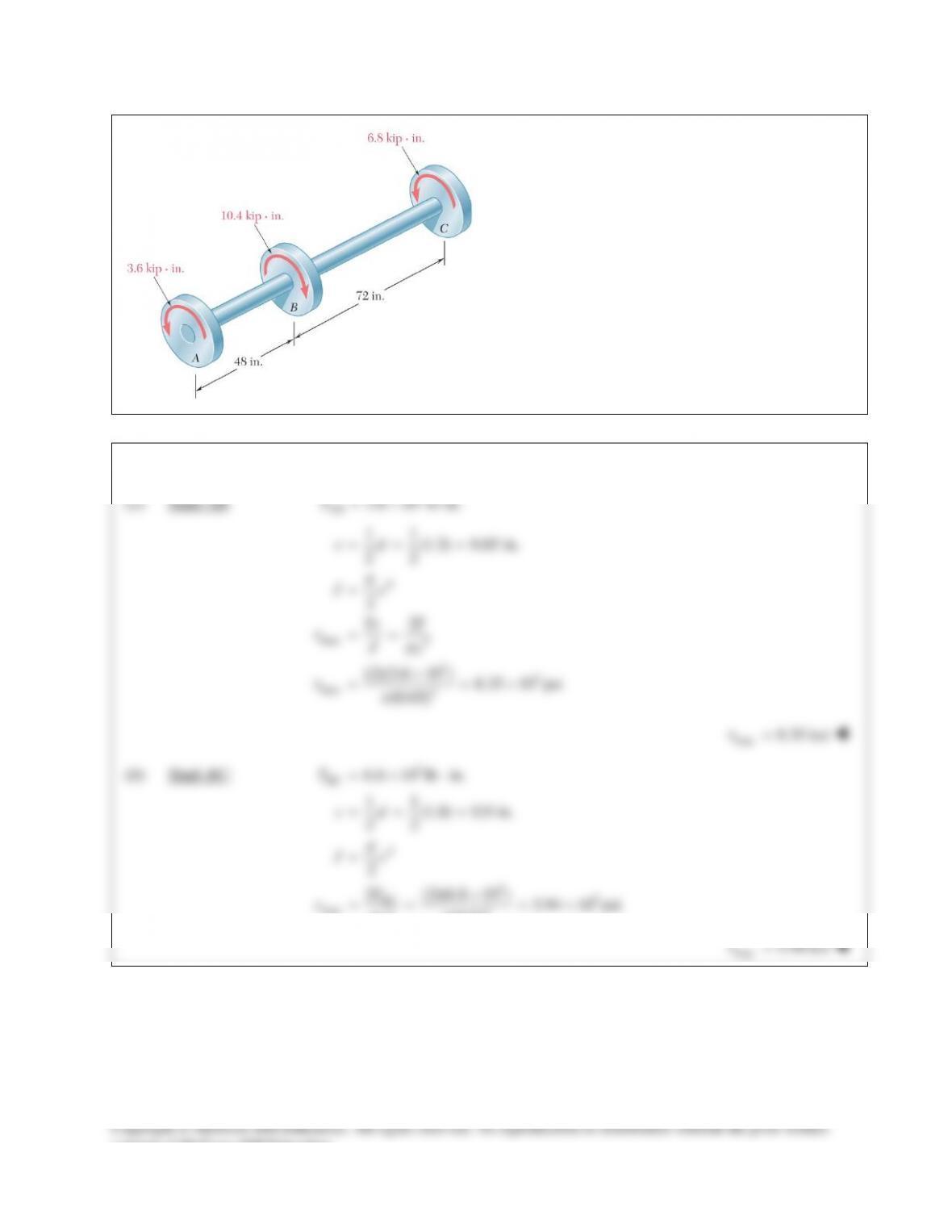
The torques shown are exerted on pulleys A, B, and C.
Knowing that both shafts are solid, determine the
maximum shearing stress in (a) shaft AB, (b) shaft BC.
SOLUTION
(a) Shaft AB:
3
3.6 10 lb in.
AB
T=×⋅
4
max 3
33
max 3
11
(1.3) 0.65 in.
22
2
2
(2)(3.6 10 ) 8.35 10 psi
(0.65)
p
τp
τp
= = =
=
= =
×
= = ×
cd
Jc
Tc T
Jc
max
8.35 ksi
τ
=
(b) Shaft BC:
3
4
33
max 33
6.8 10 lb in.
11
(1.8) 0.9 in.
22
2
2 (2)(6.8 10 ) 5.94 10 psi
(0.9)
p
τpp
=×⋅
= = =
=
×
= = = ×
BC
BC
T
cd
Jc
T
c
max
5.94 ksi
τ
=
consent of McGraw–Hill Education.
PROBLEM 10.8
The shafts of the pulley assembly shown are to be
redesigned. Knowing that the allowable shearing
stress in each shaft is 8.5 ksi, determine the smallest
allowable diameter of (a) shaft AB, (b) shaft BC.
SOLUTION
(a) Shaft AB:
3
3.6 10 lb in.
AB
T=×⋅
3
max
4max 3
3
3
33
max
8.5 ksi 8.5 10 psi
2
2
2 (2)(3.6 10 ) 0.646 in.
(8.5 10 )
AB
Tc T
Jc Jc
T
c
τ
pτp
pτ p
= = ×
= = =
×
= = =
×
2 1.292 in.
AB
dc= =
(b) Shaft BC:
3
3
max
3
3
33
max
6.8 10 lb in.
8.5 10 psi
2 (2)(6.8 10 ) 0.7985 in.
(8.5 10 )
BC
BC
T
T
c
τ
pτ p
=×⋅
= ×
×
= = =
×
2 1.597 in.
BC
dc= =
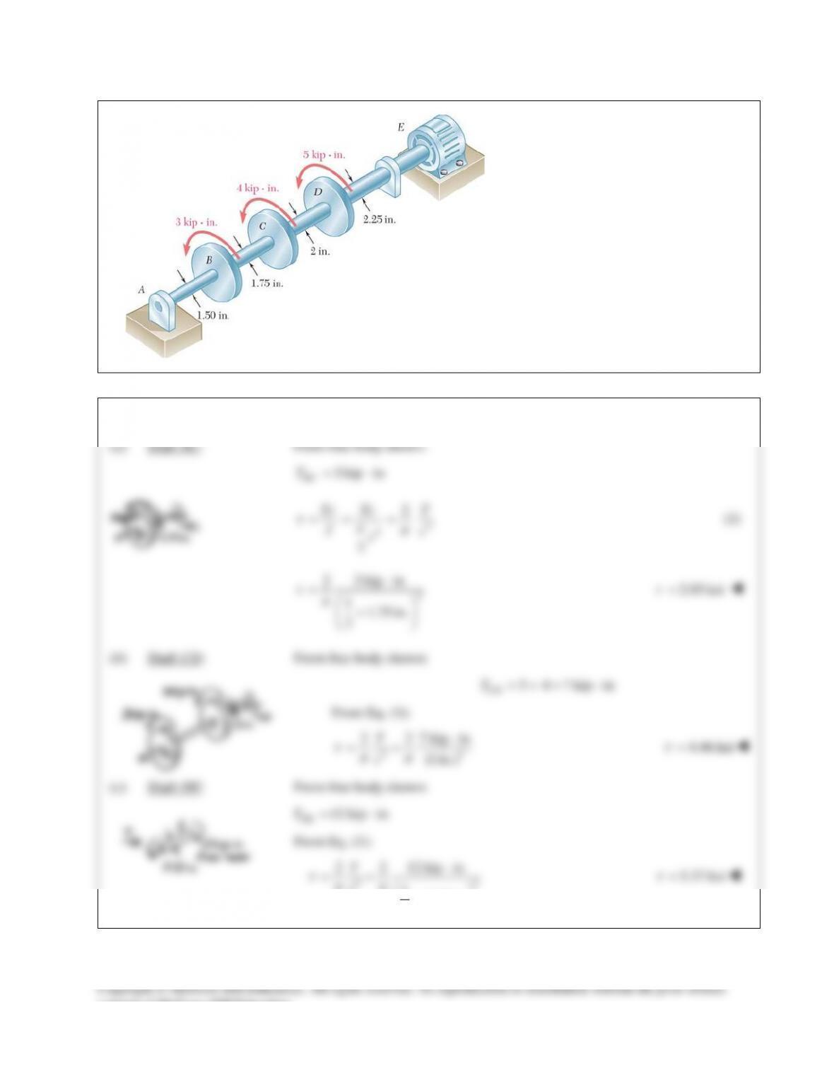
PROBLEM 10.9
Under normal operating conditions, the
electric motor exerts a 12-kip ⋅ in.
torque at E. Knowing that each shaft is
solid, determine the maximum shearing
in (a) shaft BC, (b) shaft CD, (c) shaft
DE.
SOLUTION
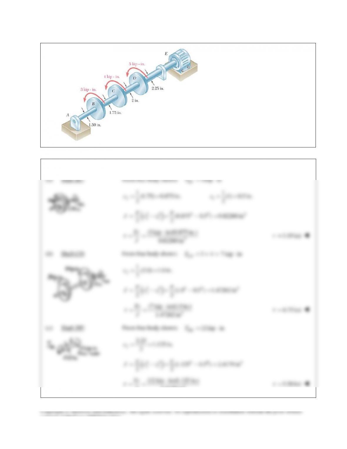
PROBLEM 10.10
Solve Prob.10.9, assuming that a 1-
in.–diameter hole has been drilled
into each shaft.
PROBLEM 10.9. Under normal
operating conditions, the electric
motor exerts a 12–kip ⋅ in. torque at
E. Knowing that each shaft is solid,
determine the maximum shearing in
(a) shaft BC, (b) shaft CD, (c) shaft
DE.
SOLUTION
PROBLEM 10.2
For the cylindrical shaft shown, determine the maximum shearing stress caused by
a torque of magnitude T = 800 N ⋅ m.
SOLUTION
4
max
max 3
3
6
;2
2
2(800 N m)
(0.018 m)
87.328 10 Pa
π
τ
τπ
π
= =
=
⋅
=
= ×
Tc Jc
J
T
c
max 87.3 MPa
τ
=
PROBLEM 10.3
(a) Determine the maximum shearing stress caused by a 40-kip ⋅ in. torque T in
the 3–in.–diameter solid aluminum shaft shown. (b) Solve part a, assuming that
the solid shaft has been replaced by a hollow shaft of the same outer diameter
and of 1-in. inner diameter.
SOLUTION
(a)
4
(40 kip in.)(1.5 in.)
(1.5 in.)
2
7.5451 ksi
τ
p
=
⋅
=
=
Tc
J
consent of McGraw–Hill Education.
PROBLEM 10.4
(a) Determine the torque that can be applied to a solid shaft of 20–mm diameter without exceeding an
allowable shearing stress of 80 MPa. (b) Solve Part a, assuming that the solid shaft has been replaced by a
hollow shaft of the same cross–sectional area and with an inner diameter equal to half of its own outer
diameter.
SOLUTION
(a) Solid shaft:
4 4 94
11
(0.020) 0.010 m
22
(0.10) 15.7080 10 m
22
cd
Jc
ππ
−
= = =
=−=×
96
max
(15.7080 10 )(80 10 ) 125.664
0.010
J
Tc
τ
−
××
= = =
125.7 N mT= ⋅
(b) Hollow shaft: Same area as solid shaft.
()
()
2
22 2 2 2
21 2 2 2
2
12
4 4 4 4 94
21
13
24
22
(0.010) 0.0115470 m
33
10.0057735 m
2
(0.0115470 0.0057735 ) 26.180 10 m
22
A cc c c c c
cc
cc
J cc
π π ππ
ππ
−
= −= − = =
= = =
= =
= −= − = ×
69
max
2
(80 10 )(26.180 10 ) 181.38
0.0115470
J
Tc
τ
−
××
= = =
181.4 N mT= ⋅
consent of McGraw–Hill Education.
PROBLEM 10.5
A torque
3 kN m
T= ⋅
is applied to the solid bronze cylinder shown.
Determine (a) the maximum shearing stress, (b) the shearing stress at point D
which lies on a 15–mm–radius circle drawn on the end of the cylinder, (c) the
percent of the torque carried by the portion of the cylinder within the 15–mm
radius.
SOLUTION
(a)
3
4 34 6 4
3
33 6
6
130 mm 30 10 m
2
(30 10 ) 1.27235 10 m
22
3 kN 3 10 N
(3 10 )(30 10 ) 70.736 10 Pa
1.27235 10
m
cd
Jc
T
Tc
J
ππ
τ
−
−−
−
−
= = = ×
==×= ×
= = ×
××
= = = ×
×
70.7 MPa
m
τ
=
(b)
3
15 mm 15 10 m
D
ρ
−
= = ×
36
3
(15 10 )(70.736 10 )
(30 10 )
D
D
c
ρ
ττ
−−
−
××
= = ×
35.4 MPa
D
τ
=
(c)
3
2
D D DD
D D DD
DD
TJ
T
J
ρ τπ
τ ρτ
ρ
= = =
33 6
3
(15 10 ) (35.368 10 ) 187.5 N m
2
187.5
100% (100%) 6.25%
3 10
D
D
T
T
T
π
−
= × ×= ⋅
×= =
×
6.25%
consent of McGraw–Hill Education.
PROBLEM 10.6
(a) For the 3–in.–diameter solid cylinder and loading shown, determine the
maximum shearing stress. (b) Determine the inner diameter of the 4–in.–
diameter hollow cylinder shown, for which the maximum stress is the
same as in part a.
SOLUTION
(a) Solid shaft:
4
11
(3.0 in.) 1.5 in.
22
2
π
= = =
=
cd
Jc
max
3
3
2
2(40 kip in.)
(1.5 in.)
7.5451 ksi
τ
π
π
=
=
⋅
=
=
Tc
J
T
c
max
7.55 ksi
τ
=
(b) Hollow shaft:
11
(4.0 in.) 2.0 in.
22
= = =
o
cd
( )
44
2
max
44
max
4
4
2
2(40 kip in.)(2.0 in.)
(2.0 in.) (7.5451 ksi)
9.2500 in 1.74395 in.
and 2 3.4879 in.
π
τ
πτ
π
−
= =
= −
⋅
= −
= ∴=
= =
oi
oo
o
io
i
ii
cc
JT
cc
Tc
cc
c
dc
3.49 in.
i
d=
consent of McGraw–Hill Education.
PROBLEM 10.7
The torques shown are exerted on pulleys A, B, and C.
Knowing that both shafts are solid, determine the
maximum shearing stress in (a) shaft AB, (b) shaft BC.
SOLUTION
(a) Shaft AB:
3
3.6 10 lb in.
AB
T=×⋅
4
max 3
33
max 3
11
(1.3) 0.65 in.
22
2
2
(2)(3.6 10 ) 8.35 10 psi
(0.65)
p
τp
τp
= = =
=
= =
×
= = ×
cd
Jc
Tc T
Jc
max
8.35 ksi
τ
=
(b) Shaft BC:
3
4
33
max 33
6.8 10 lb in.
11
(1.8) 0.9 in.
22
2
2 (2)(6.8 10 ) 5.94 10 psi
(0.9)
p
τpp
=×⋅
= = =
=
×
= = = ×
BC
BC
T
cd
Jc
T
c
max
5.94 ksi
τ
=
consent of McGraw–Hill Education.
PROBLEM 10.8
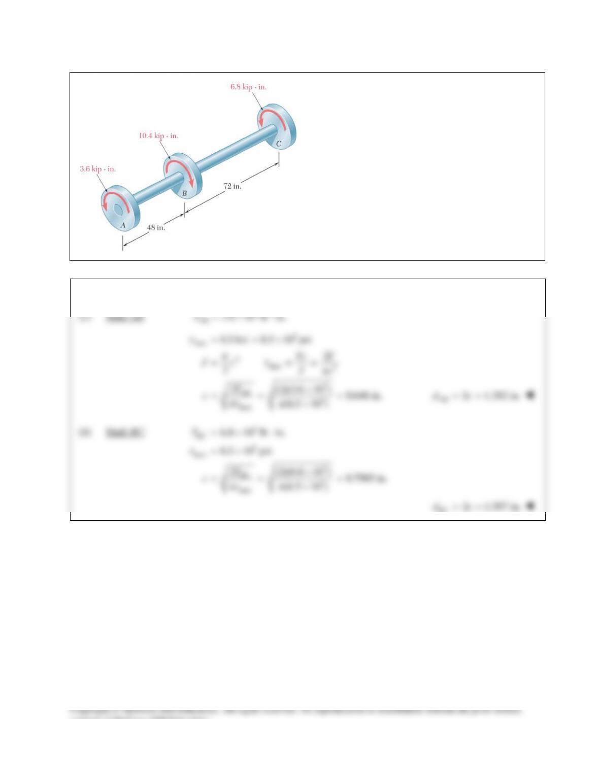
The shafts of the pulley assembly shown are to be
redesigned. Knowing that the allowable shearing
stress in each shaft is 8.5 ksi, determine the smallest
allowable diameter of (a) shaft AB, (b) shaft BC.
SOLUTION
(a) Shaft AB:
3
3.6 10 lb in.
AB
T=×⋅
3
max
4max 3
3
3
33
max
8.5 ksi 8.5 10 psi
2
2
2 (2)(3.6 10 ) 0.646 in.
(8.5 10 )
AB
Tc T
Jc Jc
T
c
τ
pτp
pτ p
= = ×
= = =
×
= = =
×
2 1.292 in.
AB
dc= =
(b) Shaft BC:
3
3
max
3
3
33
max
6.8 10 lb in.
8.5 10 psi
2 (2)(6.8 10 ) 0.7985 in.
(8.5 10 )
BC
BC
T
T
c
τ
pτ p
=×⋅
= ×
×
= = =
×
2 1.597 in.
BC
dc= =
PROBLEM 10.9
Under normal operating conditions, the
electric motor exerts a 12-kip ⋅ in.
torque at E. Knowing that each shaft is
solid, determine the maximum shearing
in (a) shaft BC, (b) shaft CD, (c) shaft
DE.
SOLUTION
PROBLEM 10.10
Solve Prob.10.9, assuming that a 1-
in.–diameter hole has been drilled
into each shaft.
PROBLEM 10.9. Under normal
operating conditions, the electric
motor exerts a 12–kip ⋅ in. torque at
E. Knowing that each shaft is solid,
determine the maximum shearing in
(a) shaft BC, (b) shaft CD, (c) shaft
DE.
SOLUTION