PROBLEM 8.57
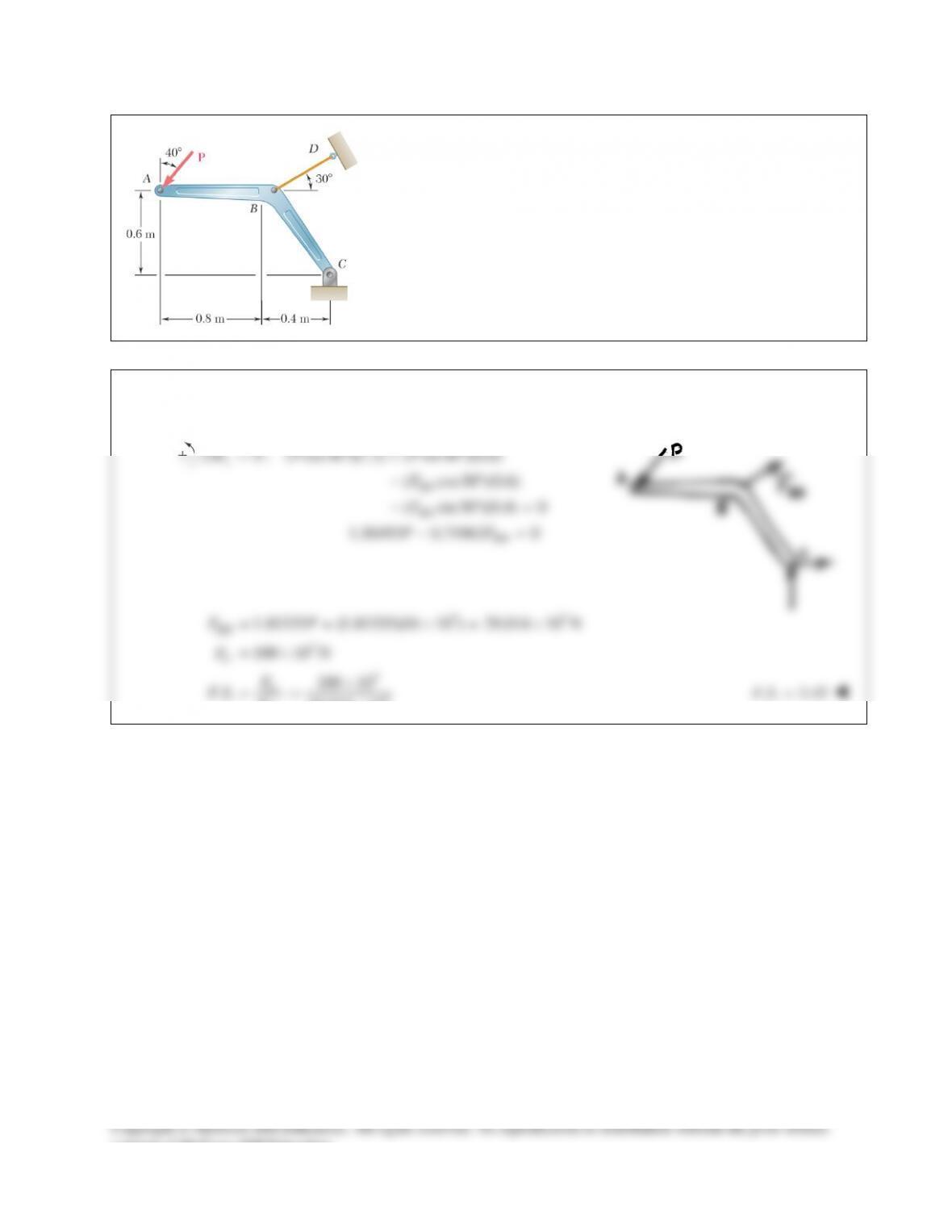
Member ABC, which is supported by a pin and bracket at C and a cable
BD, was designed to support the 16–kN load P as shown. Knowing that
the ultimate load for cable BD is 100 kN, determine the factor of safety
with respect to cable failure.
SOLUTION
Use member ABC as a free body, and note that member BD is a two–force member.
0 : ( cos40 )(1.2) ( sin40 )(0.6)
( cos30 )(0.6)
( sin30 )(0.4) 0
1.30493 0.71962 0
c
BD
BD
BD
MP P
F
F
PF
Σ= ° + °
−°
− °=
−=
33
3
3
3
1.81335 (1.81335)(16 10 ) 29.014 10 N
100 10 N
100 10
.. 29.014 10
= = ×= ×
= ×
×
= = ×
BD
U
U
BD
FP
F
F
FS F
. . 3.45=
FS
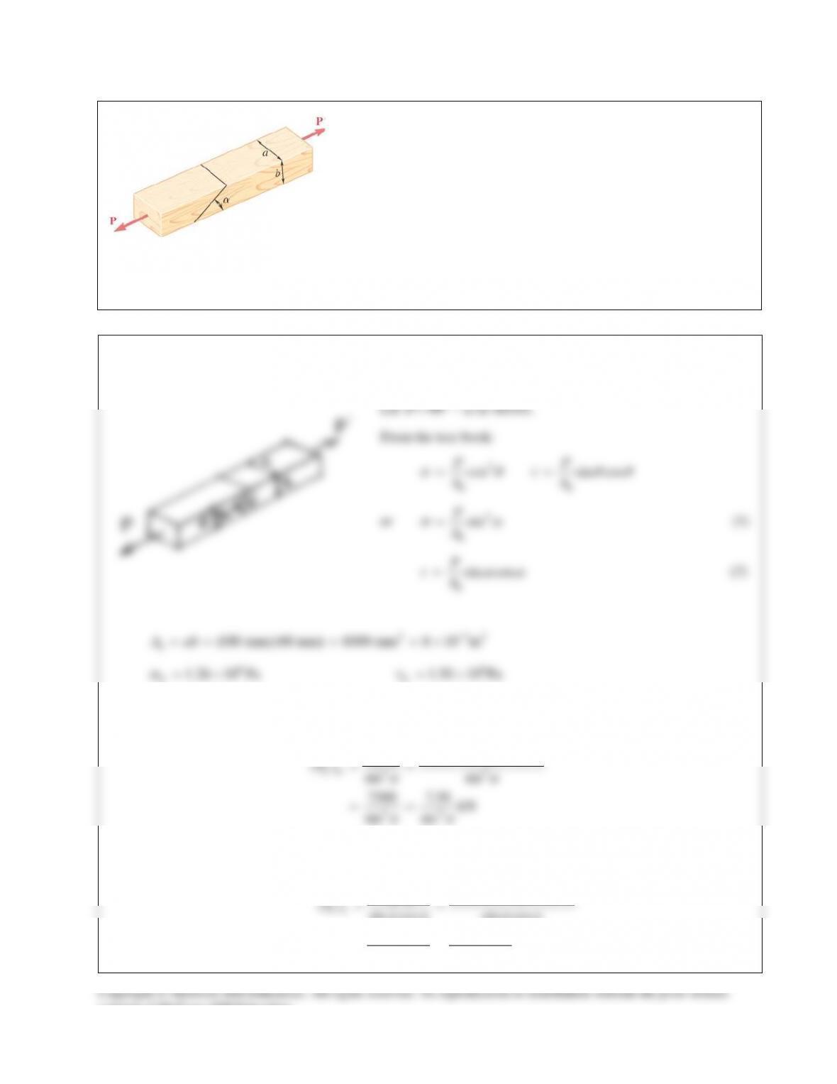
PROBLEM 8.58
Two wooden members of uniform rectangular cross section of sides
a = 100 mm and b = 60 mm are joined by a simple glued joint as shown.
Knowing that the ultimate stresses for the joint are
1.26 MPa
U
σ
=
in
tension and
1.50 MPa
τ
=
U
in shear, and that P = 6 kN, determine the
factor of safety for the joint when (a)
α
= 20°, (b)
α
= 35°,
(c)
α
= 45°. For each of these values of
α
, also determine whether the
joint will fail in tension or in shear if P is increased until rupture
occurs.
SOLUTION
SOLUTION Continued
(a)
2
7.56
20 : ( ) 64.63 kN
sin 20
9.00
( ) 28.00 kN
sin 20 cos20
U
U
P
P
σ
τ
α
=°= =
°
= = =
°°
The smaller value governs. The joint will fail in shear and
28.00 kN.
U
P=
28.00
.. 6
U
P
FS P
= =
. . 4.67FS =
(b)
2
7.56
35 : ( ) 22.98 kN
sin 35
9.00
( ) 19.155 kN
sin35 cos35
U
U
P
P
σ
τ
α
=°==
°
= =
°°
The joint will fail in shear and
19.155 kN.
U
P=
19.155
.. 6
U
P
FS P
= =
. . 3.19FS =
(c)
2
7.56
45 : ( ) 15.12 kN
sin 45
9.00
( ) 18.00 kN
sin 45 cos45
U
U
P
P
σ
τ
α
=°= =
°
= =
°°
The joint will fail in tension and
15.12 kN.
U
P=
15.12
.. 6
U
P
FS P
= =
. . 2.52FS =
consent of McGraw–Hill Education.
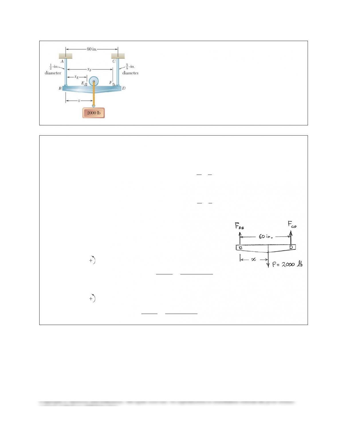
PROBLEM 8.59
The 2000–lb load can be moved along the beam BD to any position
between stops at E and F. Knowing that
all 6
σ
=
ksi for the steel
used in rods AB and CD, determine where the stops should be
placed if the permitted motion of the load is to be as large as
possible.
SOLUTION
Permitted member forces:
2
max all
2
max all
1
: ( ) (6) 42
1.17810 kips
5
: ( ) (6) 48
1.84078 kips
AB AB
CD CD
AB F A
CD F A
p
σ
p
σ
= =
=
= =
=
Use member BEFD as a free body.
2000 lb 2.000 kips= =P
0 : (60) (60 x ) 0
60 (60)(1.17810)
60 x 2.000
D AB E
AB
E
MFP
F
P
Σ= − + − =
−= =
35.343=
x 24.7 in.=
E
0 : 60 x 0Σ= − =
B CD F
M FP
60 (60)(1.84078)
x2.000
= =
CD
F
F
P
x 55.2 in.
F
=
consent of McGraw–Hill Education.
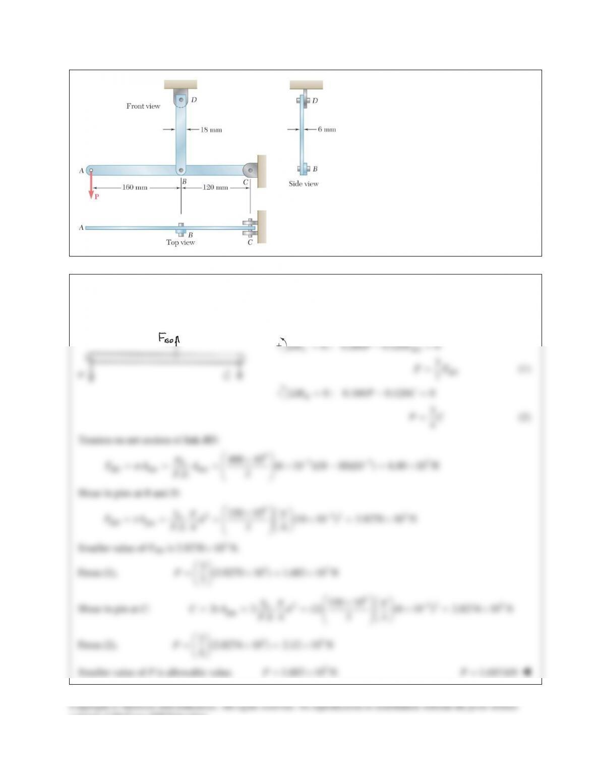
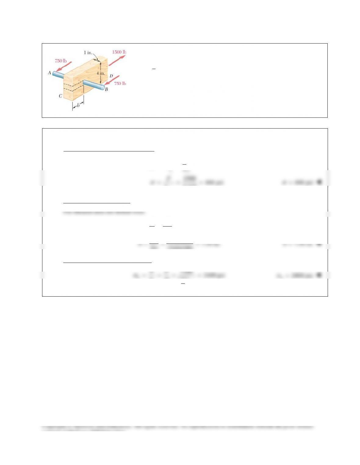
PROBLEM 8.60
In the steel structure shown, a 6–mm–
diameter pin is used at C and 10–mm–
diameter pins are used at B and D. The
ultimate shearing stress is 150 MPa at all
connections, and the ultimate normal
stress is 400 MPa in link BD. Knowing
that a factor of safety of 3.0 is desired,
determine the largest load P that can be
applied at A. Note that link BD is not
reinforced around the pin holes.
SOLUTION
Use free body ABC.
0 : 0.280 0.120 0Σ= − =
C BD
M PF
3
7
BD
PF=
(1)
0 : 0.160 0.120 0
B
M PCΣ= − =
3
4
PC=
(2)
Tension on net section of link BD:
63 33
net net 400 10 (6 10 )(18 10)(10 ) 6.40 10 N
.. 3
σ
σ
−−
×
== = ×− =×
U
BD
FA A
FS
Shear in pins at B and D:
6
2 32 3
pin
150 10 (10 10 ) 3.9270 10 N
. .4 3 4
τp p
τ
−
×
== = ×= ×
U
BD
FA d
FS
Smaller value of FBD is
3
3.9270 10 N.×
From (1),
33
3(3.9270 10 ) 1.683 10 N
7
= ×= ×
P
Shear in pin at C:
6
2 32 3
pin 150 10
2 2 (2) (6 10 ) 2.8274 10 N
. .4 3 4
U
CA d
FS
τp p
τ
−
×
= = = ×= ×
From (2),
33
3(2.8274 10 ) 2.12 10 N
4
= ×=×
P
Smaller value of P is allowable value.
3
1.683 10 N= ×P
1.683 kN
=P
consent of McGraw–Hill Education.
PROBLEM 8.57
Member ABC, which is supported by a pin and bracket at C and a cable
BD, was designed to support the 16–kN load P as shown. Knowing that
the ultimate load for cable BD is 100 kN, determine the factor of safety
with respect to cable failure.
SOLUTION
Use member ABC as a free body, and note that member BD is a two–force member.
0 : ( cos40 )(1.2) ( sin40 )(0.6)
( cos30 )(0.6)
( sin30 )(0.4) 0
1.30493 0.71962 0
c
BD
BD
BD
MP P
F
F
PF
Σ= ° + °
−°
− °=
−=
33
3
3
3
1.81335 (1.81335)(16 10 ) 29.014 10 N
100 10 N
100 10
.. 29.014 10
= = ×= ×
= ×
×
= = ×
BD
U
U
BD
FP
F
F
FS F
. . 3.45=
FS
PROBLEM 8.58
Two wooden members of uniform rectangular cross section of sides
a = 100 mm and b = 60 mm are joined by a simple glued joint as shown.
Knowing that the ultimate stresses for the joint are
1.26 MPa
U
σ
=
in
tension and
1.50 MPa
τ
=
U
in shear, and that P = 6 kN, determine the
factor of safety for the joint when (a)
α
= 20°, (b)
α
= 35°,
(c)
α
= 45°. For each of these values of
α
, also determine whether the
joint will fail in tension or in shear if P is increased until rupture
occurs.
SOLUTION
SOLUTION Continued
(a)
2
7.56
20 : ( ) 64.63 kN
sin 20
9.00
( ) 28.00 kN
sin 20 cos20
U
U
P
P
σ
τ
α
=°= =
°
= = =
°°
The smaller value governs. The joint will fail in shear and
28.00 kN.
U
P=
28.00
.. 6
U
P
FS P
= =
. . 4.67FS =
(b)
2
7.56
35 : ( ) 22.98 kN
sin 35
9.00
( ) 19.155 kN
sin35 cos35
U
U
P
P
σ
τ
α
=°==
°
= =
°°
The joint will fail in shear and
19.155 kN.
U
P=
19.155
.. 6
U
P
FS P
= =
. . 3.19FS =
(c)
2
7.56
45 : ( ) 15.12 kN
sin 45
9.00
( ) 18.00 kN
sin 45 cos45
U
U
P
P
σ
τ
α
=°= =
°
= =
°°
The joint will fail in tension and
15.12 kN.
U
P=
15.12
.. 6
U
P
FS P
= =
. . 2.52FS =
consent of McGraw–Hill Education.
PROBLEM 8.59
The 2000–lb load can be moved along the beam BD to any position
between stops at E and F. Knowing that
all 6
σ
=
ksi for the steel
used in rods AB and CD, determine where the stops should be
placed if the permitted motion of the load is to be as large as
possible.
SOLUTION
Permitted member forces:
2
max all
2
max all
1
: ( ) (6) 42
1.17810 kips
5
: ( ) (6) 48
1.84078 kips
AB AB
CD CD
AB F A
CD F A
p
σ
p
σ
= =
=
= =
=
Use member BEFD as a free body.
2000 lb 2.000 kips= =P
0 : (60) (60 x ) 0
60 (60)(1.17810)
60 x 2.000
D AB E
AB
E
MFP
F
P
Σ= − + − =
−= =
35.343=
x 24.7 in.=
E
0 : 60 x 0Σ= − =
B CD F
M FP
60 (60)(1.84078)
x2.000
= =
CD
F
F
P
x 55.2 in.
F
=
consent of McGraw–Hill Education.
PROBLEM 8.60
In the steel structure shown, a 6–mm–
diameter pin is used at C and 10–mm–
diameter pins are used at B and D. The
ultimate shearing stress is 150 MPa at all
connections, and the ultimate normal
stress is 400 MPa in link BD. Knowing
that a factor of safety of 3.0 is desired,
determine the largest load P that can be
applied at A. Note that link BD is not
reinforced around the pin holes.
SOLUTION
Use free body ABC.
0 : 0.280 0.120 0Σ= − =
C BD
M PF
3
7
BD
PF=
(1)
0 : 0.160 0.120 0
B
M PCΣ= − =
3
4
PC=
(2)
Tension on net section of link BD:
63 33
net net 400 10 (6 10 )(18 10)(10 ) 6.40 10 N
.. 3
σ
σ
−−
×
== = ×− =×
U
BD
FA A
FS
Shear in pins at B and D:
6
2 32 3
pin
150 10 (10 10 ) 3.9270 10 N
. .4 3 4
τp p
τ
−
×
== = ×= ×
U
BD
FA d
FS
Smaller value of FBD is
3
3.9270 10 N.×
From (1),
33
3(3.9270 10 ) 1.683 10 N
7
= ×= ×
P
Shear in pin at C:
6
2 32 3
pin 150 10
2 2 (2) (6 10 ) 2.8274 10 N
. .4 3 4
U
CA d
FS
τp p
τ
−
×
= = = ×= ×
From (2),
33
3(2.8274 10 ) 2.12 10 N
4
= ×=×
P
Smaller value of P is allowable value.
3
1.683 10 N= ×P
1.683 kN
=P
consent of McGraw–Hill Education.