members AD and EG has a 10 40-mm uniform rectangular cross
section and is made of a steel with an ultimate strength in tension of
400 MPa, while each of the pins at C and F has a 20–mm diameter and
are made of a steel with an ultimate strength in shear of 150 MPa.
Determine the overall factor of safety for the links CF and the pins
connecting them to the horizontal members.
SOLUTION
3
3
0 : 0.40 (0.65)(24 10 ) 0
39 10 N
E CF
CF
MF
F
Σ= − × =
= ×
Based on tension in links CF,
62
66 3
( ) (0.040 0.02)(0.010) 200 10 m (one link)
2 (2)(400 10 )(200 10 ) 160.0 10 N
UU
A b dt
FA
σ
−
−
=−= − =×
= = × ×=×
Based on double shear in pins,
2 2 62
66 3
(0.020) 314.16 10 m
44
2 (2)(150 10 )(314.16 10 ) 94.248 10 N
UU
Ad
FA
ππ
τ
−
−
= = = ×
= = × ×= ×
Actual FU is smaller value, i.e.
3
94.248 10 N
U
F= ×
Factor of safety:
3
3
94.248 10
.. 39 10
U
CF
F
FS F
×
= = ×
. . 2.42FS =
consent of McGraw–Hill Education.
PROBLEM 8.48
Solve Prob. 8.47, assuming that the pins at C and F have been replaced by
pins with a 30-mm diameter.
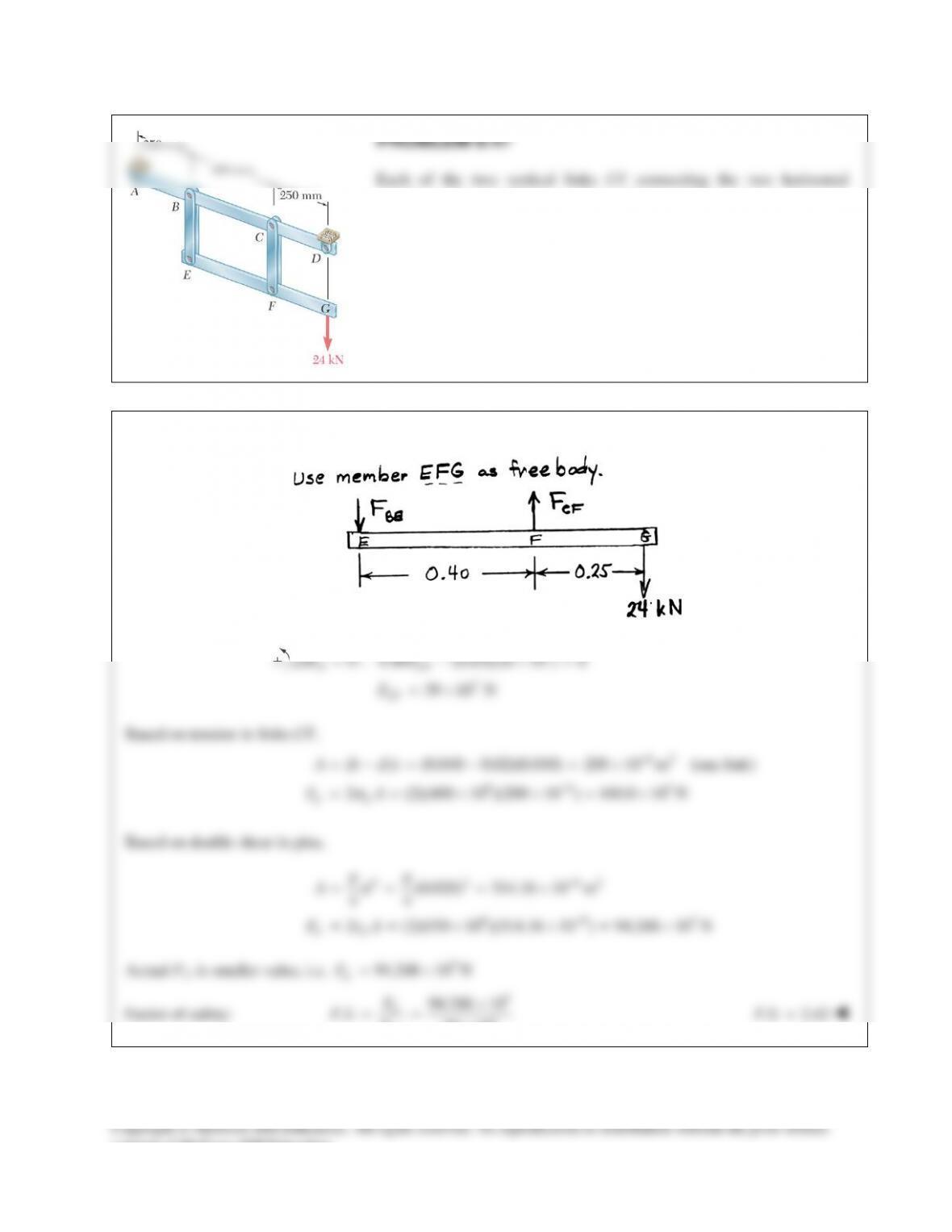
PROBLEM 8.47 Each of the two vertical links CF connecting the two
horizontal members AD and EG has a 10 40-mm uniform rectangular
cross section and is made of a steel with an ultimate strength in tension of
400 MPa, while each of the pins at C and F has a 20–mm diameter and are
made of a steel with an ultimate strength in shear of 150 MPa. Determine
the overall factor of safety for the links CF and the pins connecting them
to the horizontal members.
SOLUTION
Use member EFG as free body.
3
3
0 : 0.40 (0.65)(24 10 ) 0
39 10 N
E CF
CF
MF
F
Σ= − × =
= ×
Based on tension in links CF,
62
66 3
( ) (0.040 0.030)(0.010) 100 10 m (one link)
2 (2)(400 10 )(100 10 ) 80.0 10 N
UU
A b dt
FA
σ
−
−
=−= − =×
= = × ×=×
Based on double shear in pins,
2 2 62
66 3
(0.030) 706.86 10 m
44
2 (2)(150 10 )(706.86 10 ) 212.06 10 N
UU
Ad
FA
ππ
τ
−
−
= = = ×
= = × ×= ×
Actual FU is smaller value, i.e.
3
80.0 10 N
U
F= ×
Factor of safety:
3
3
80.0 10
.. 39 10
U
CF
F
FS F
×
= = ×
. . 2.05FS =
consent of McGraw–Hill Education.
PROBLEM 8.49
A 40–kN axial load is applied to a short wooden post that is
supported by a concrete footing resting on undisturbed soil.
Determine (a) the maximum bearing stress on the concrete
footing, (b) the size of the footing for which the average bearing
stress in the soil is 145 kPa.
SOLUTION
PROBLEM 8.50
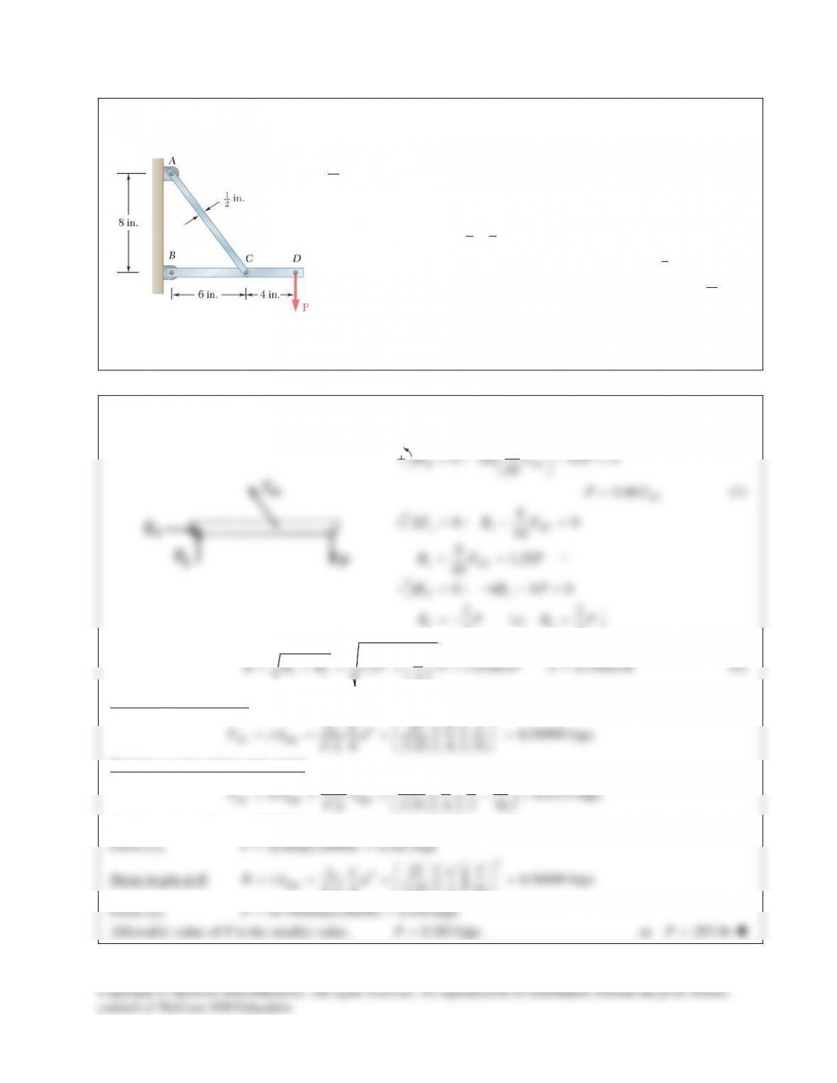
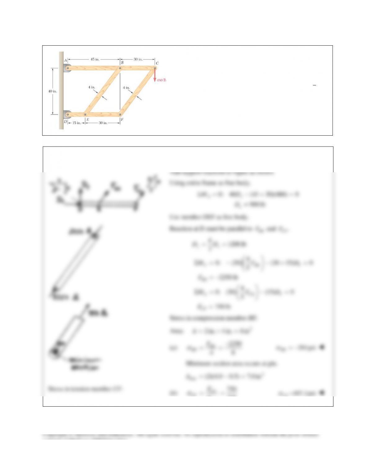
The frame shown consists of four wooden members, ABC,
DEF, BE, and CF. Knowing that each member has a 2 × 4-in.
rectangular cross section and that each pin has a
1
2
-in.
diameter, determine the maximum value of the average
normal stress (a) in member BE, (b) in member CF.
SOLUTION
PROBLEM 8.51
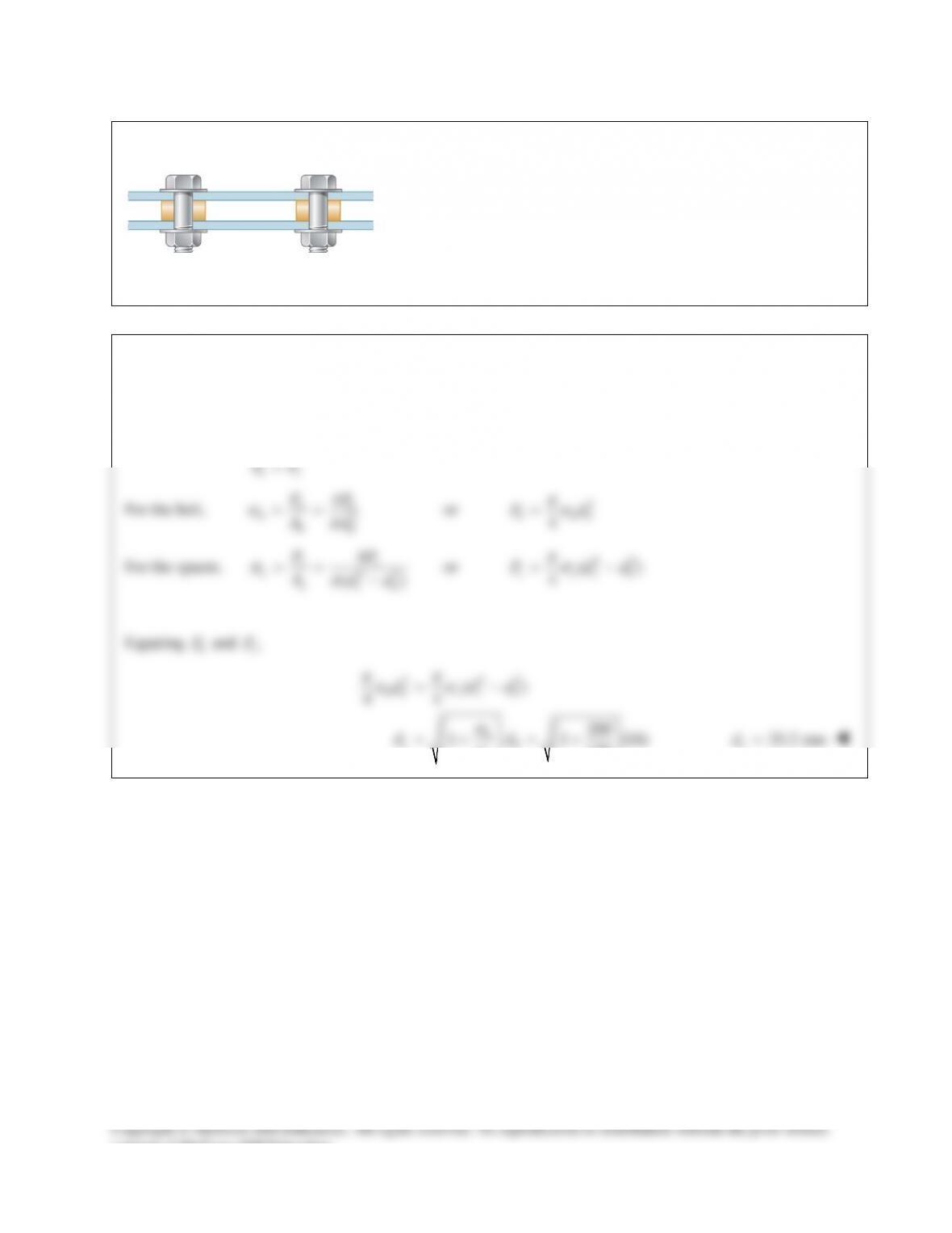
Two steel plates are to be held together by means of 16–mm–
diameter high–strength steel bolts fitting snugly inside cylindrical
brass spacers. Knowing that the average normal stress must not
exceed 200 MPa in the bolts and 130 MPa in the spacers,
determine the outer diameter of the spacers that yields the most
economical and safe design.
SOLUTION
At each bolt location the upper plate is pulled down by the tensile force Pb of the bolt. At the same time, the
spacer pushes that plate upward with a compressive force Ps in order to maintain equilibrium.
=
bs
PP
For the bolt,
2
4
σπ
= =
bb
bbb
FP
Ad
or
2
4
πσ
=
b bb
Pd
For the spacer,
22
4
()
σπ
= = −
ss
sssb
PP
Add
or
22
()
4
s ss b
P dd
πσ
= −
Equating
b
P
and
,
s
P
2 22
()
44
200
1 1 (16)
130
bb s s b
b
sb
s
d dd
dd
ππ
σσ
σ
σ
= −
=+=+
25.2 mm
=
s
d
consent of McGraw–Hill Education.
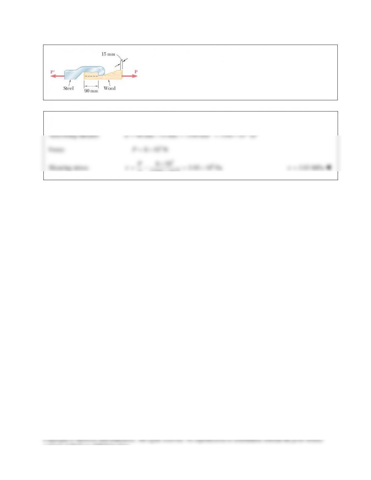
PROBLEM 8.52
When the force P reached 8 kN, the wooden specimen shown failed in
shear along the surface indicated by the dashed line. Determine the
average shearing stress along that surface at the time of failure.
SOLUTION
Area being sheared:
2 62
90 mm 15 mm 1350 mm 1350 10 m
−
=×= =×A
Force:
3
8 10 N= ×P
Shearing stress:
36
6
8 10 5.93 10 Pa
1350 10
τ
−
×
=−=×
×
P
A
5.93 MPa
τ
=
consent of McGraw–Hill Education.
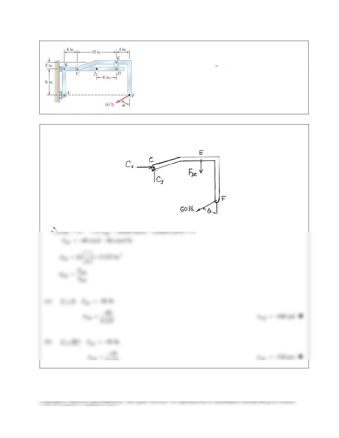
PROBLEM 8.53
Knowing that the link DE is
1
8
in. thick and 1 in. wide, determine
the normal stress in the central portion of that link when
(a)
0,
θ
= °
(b)
90 .
θ
= °
SOLUTION
Use member CEF as a free body.
0 : 12 (8)(60 sin ) (16)(60 cos ) 0
40 sin 80 cos lb.
C DE
DE
MF
F
θθ
θθ
Σ= − − − =
=−−
2
1
(1) 0.125 in.
8
DE
DE
DE DE
A
F
A
σ
= =
=
(a)
0: 80 lb.
DE
F
θ
= = −
80
0.125
σ
−
=
DE
640 psi
σ
= −
DE
(b)
90 : 40 lb.
DE
F
θ
=°=−
40
0.125
DE
σ
−
=
320 psi
σ
= −
DE
consent of McGraw–Hill Education.
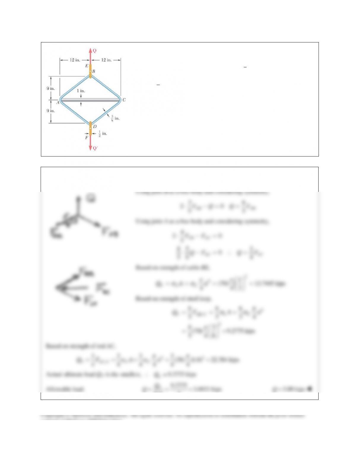
PROBLEM 8.54
A steel loop ABCD of length 5 ft and of
3
8
–in. diameter is placed as
shown around a 1–in.–diameter aluminum rod AC. Cables BE and DF,
each of
1
2
–in. diameter, are used to apply the load Q. Knowing that the
ultimate strength of the steel used for the loop and the cables is 70 ksi,
and that the ultimate strength of the aluminum used for the rod is 38 ksi,
determine the largest load Q that can be applied if an overall factor of
safety of 3 is desired.
SOLUTION
PROBLEM 8.55
The hydraulic cylinder CF, which partially controls the position of rod
DE, has been locked in the position shown. Member BD is 15 mm
thick and is connected at C to the vertical rod by a 9–mm–diameter
bolt. Knowing that P = 2 kN and
75 ,
θ
= °
determine (a) the average
shearing stress in the bolt, (b) the bearing stress at C in member BD.
SOLUTION
Free Body: Member BD.
40 9
0: (100 cos20 ) (100 sin 20 )
41 4
c AB AB
MF F
Σ = °− °
(2 kN)cos75 (175sin 20 ) (2 kN)sin75 (175cos20) 0− ° °− ° °=
100 (40cos20 9sin 20 ) (2 kN)(175)sin(75 20 )
41
4.1424 kN
AB
AB
F
F
°− ° = °+ °
=
9
0: (4.1424 kN) (2 kN)cos75 0
41
0.39167 kN
Σ = − + °=
=
xx
x
FC
C
40
0: (4.1424 kN) (2 kN)sin 75 0
41
5.9732 kN
Σ = − − °=
=
yy
y
FC
C
5.9860 kN=C
86.2°
(a)
36
ave 2
5.9860 10 N 94.1 10 Pa 94.1 MPa
(0.0045 m)
τπ
×
== =×=
C
A
(b)
36
5.9860 10 N 44.3 10 Pa 44.3 MPa
(0.015 m)(0.009 m)
bC
td
τ
×
== =×=
consent of McGraw–Hill Education.
members AD and EG has a 10 40-mm uniform rectangular cross
section and is made of a steel with an ultimate strength in tension of
400 MPa, while each of the pins at C and F has a 20–mm diameter and
are made of a steel with an ultimate strength in shear of 150 MPa.
Determine the overall factor of safety for the links CF and the pins
connecting them to the horizontal members.
SOLUTION
3
3
0 : 0.40 (0.65)(24 10 ) 0
39 10 N
E CF
CF
MF
F
Σ= − × =
= ×
Based on tension in links CF,
62
66 3
( ) (0.040 0.02)(0.010) 200 10 m (one link)
2 (2)(400 10 )(200 10 ) 160.0 10 N
UU
A b dt
FA
σ
−
−
=−= − =×
= = × ×=×
Based on double shear in pins,
2 2 62
66 3
(0.020) 314.16 10 m
44
2 (2)(150 10 )(314.16 10 ) 94.248 10 N
UU
Ad
FA
ππ
τ
−
−
= = = ×
= = × ×= ×
Actual FU is smaller value, i.e.
3
94.248 10 N
U
F= ×
Factor of safety:
3
3
94.248 10
.. 39 10
U
CF
F
FS F
×
= = ×
. . 2.42FS =
consent of McGraw–Hill Education.
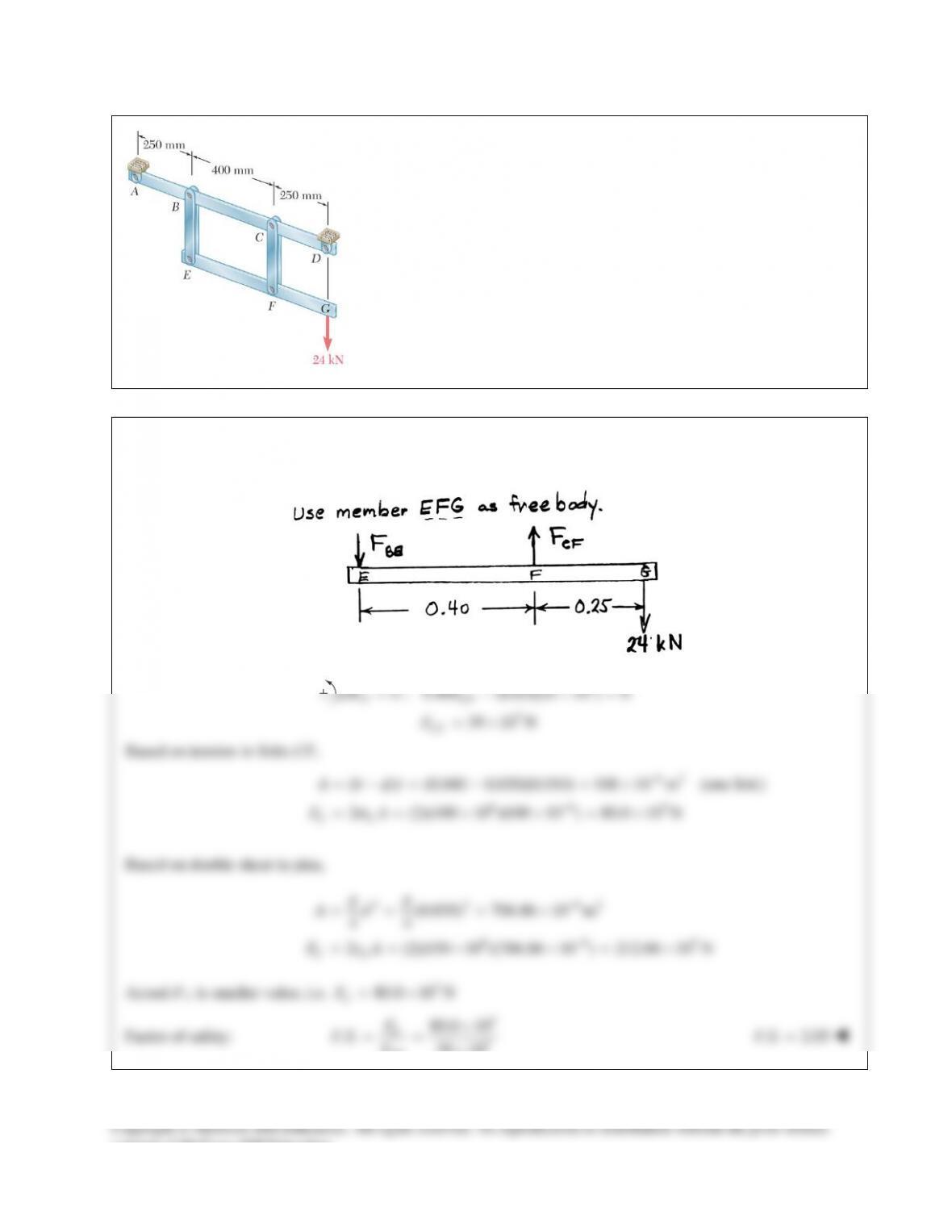
PROBLEM 8.48
Solve Prob. 8.47, assuming that the pins at C and F have been replaced by
pins with a 30-mm diameter.
PROBLEM 8.47 Each of the two vertical links CF connecting the two
horizontal members AD and EG has a 10 40-mm uniform rectangular
cross section and is made of a steel with an ultimate strength in tension of
400 MPa, while each of the pins at C and F has a 20–mm diameter and are
made of a steel with an ultimate strength in shear of 150 MPa. Determine
the overall factor of safety for the links CF and the pins connecting them
to the horizontal members.
SOLUTION
Use member EFG as free body.
3
3
0 : 0.40 (0.65)(24 10 ) 0
39 10 N
E CF
CF
MF
F
Σ= − × =
= ×
Based on tension in links CF,
62
66 3
( ) (0.040 0.030)(0.010) 100 10 m (one link)
2 (2)(400 10 )(100 10 ) 80.0 10 N
UU
A b dt
FA
σ
−
−
=−= − =×
= = × ×=×
Based on double shear in pins,
2 2 62
66 3
(0.030) 706.86 10 m
44
2 (2)(150 10 )(706.86 10 ) 212.06 10 N
UU
Ad
FA
ππ
τ
−
−
= = = ×
= = × ×= ×
Actual FU is smaller value, i.e.
3
80.0 10 N
U
F= ×
Factor of safety:
3
3
80.0 10
.. 39 10
U
CF
F
FS F
×
= = ×
. . 2.05FS =
consent of McGraw–Hill Education.
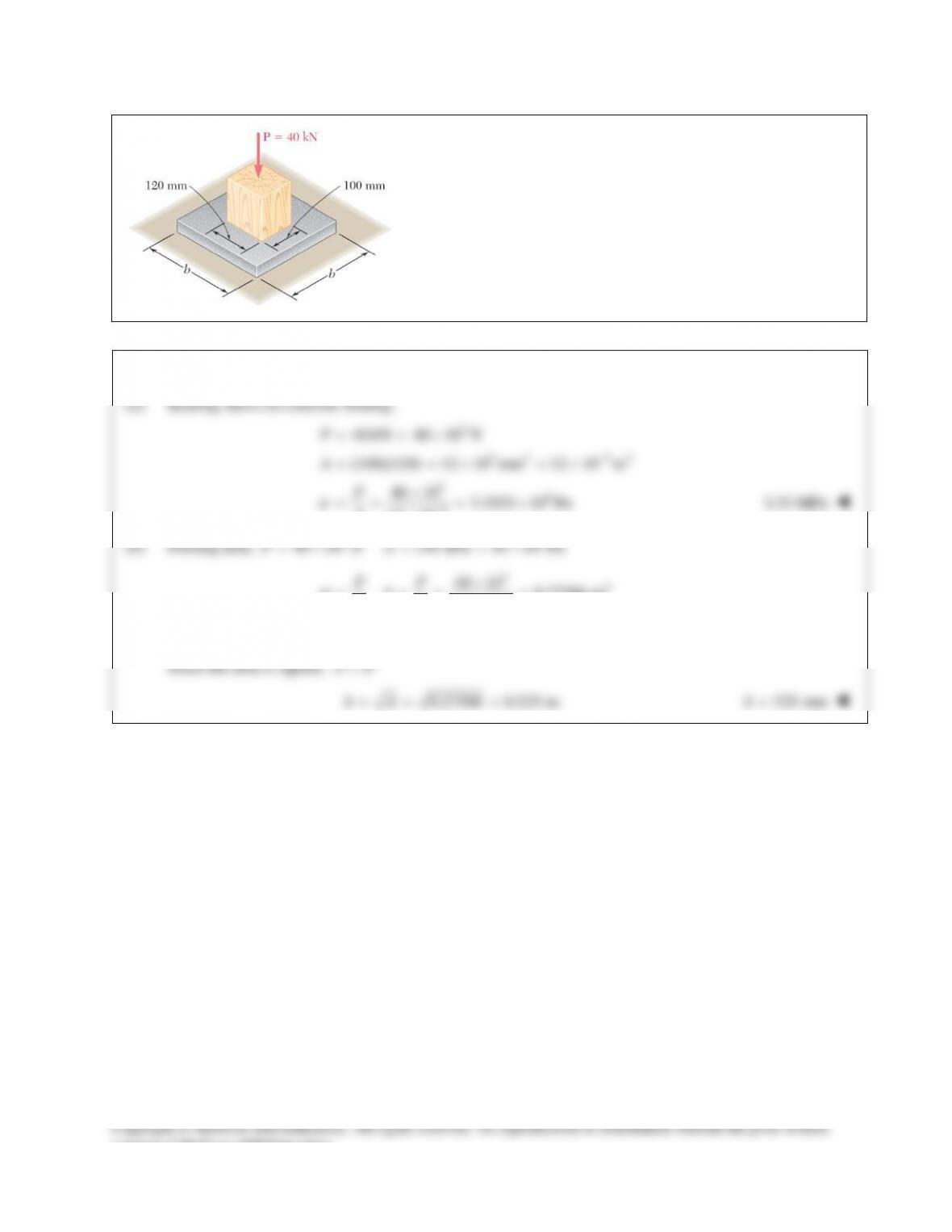
PROBLEM 8.49
A 40–kN axial load is applied to a short wooden post that is
supported by a concrete footing resting on undisturbed soil.
Determine (a) the maximum bearing stress on the concrete
footing, (b) the size of the footing for which the average bearing
stress in the soil is 145 kPa.
SOLUTION
PROBLEM 8.50
The frame shown consists of four wooden members, ABC,
DEF, BE, and CF. Knowing that each member has a 2 × 4-in.
rectangular cross section and that each pin has a
1
2
-in.
diameter, determine the maximum value of the average
normal stress (a) in member BE, (b) in member CF.
SOLUTION
PROBLEM 8.51
Two steel plates are to be held together by means of 16–mm–
diameter high–strength steel bolts fitting snugly inside cylindrical
brass spacers. Knowing that the average normal stress must not
exceed 200 MPa in the bolts and 130 MPa in the spacers,
determine the outer diameter of the spacers that yields the most
economical and safe design.
SOLUTION
At each bolt location the upper plate is pulled down by the tensile force Pb of the bolt. At the same time, the
spacer pushes that plate upward with a compressive force Ps in order to maintain equilibrium.
=
bs
PP
For the bolt,
2
4
σπ
= =
bb
bbb
FP
Ad
or
2
4
πσ
=
b bb
Pd
For the spacer,
22
4
()
σπ
= = −
ss
sssb
PP
Add
or
22
()
4
s ss b
P dd
πσ
= −
Equating
b
P
and
,
s
P
2 22
()
44
200
1 1 (16)
130
bb s s b
b
sb
s
d dd
dd
ππ
σσ
σ
σ
= −
=+=+
25.2 mm
=
s
d
consent of McGraw–Hill Education.
PROBLEM 8.52
When the force P reached 8 kN, the wooden specimen shown failed in
shear along the surface indicated by the dashed line. Determine the
average shearing stress along that surface at the time of failure.
SOLUTION
Area being sheared:
2 62
90 mm 15 mm 1350 mm 1350 10 m
−
=×= =×A
Force:
3
8 10 N= ×P
Shearing stress:
36
6
8 10 5.93 10 Pa
1350 10
τ
−
×
=−=×
×
P
A
5.93 MPa
τ
=
consent of McGraw–Hill Education.
PROBLEM 8.53
Knowing that the link DE is
1
8
in. thick and 1 in. wide, determine
the normal stress in the central portion of that link when
(a)
0,
θ
= °
(b)
90 .
θ
= °
SOLUTION
Use member CEF as a free body.
0 : 12 (8)(60 sin ) (16)(60 cos ) 0
40 sin 80 cos lb.
C DE
DE
MF
F
θθ
θθ
Σ= − − − =
=−−
2
1
(1) 0.125 in.
8
DE
DE
DE DE
A
F
A
σ
= =
=
(a)
0: 80 lb.
DE
F
θ
= = −
80
0.125
σ
−
=
DE
640 psi
σ
= −
DE
(b)
90 : 40 lb.
DE
F
θ
=°=−
40
0.125
DE
σ
−
=
320 psi
σ
= −
DE
consent of McGraw–Hill Education.
PROBLEM 8.54
A steel loop ABCD of length 5 ft and of
3
8
–in. diameter is placed as
shown around a 1–in.–diameter aluminum rod AC. Cables BE and DF,
each of
1
2
–in. diameter, are used to apply the load Q. Knowing that the
ultimate strength of the steel used for the loop and the cables is 70 ksi,
and that the ultimate strength of the aluminum used for the rod is 38 ksi,
determine the largest load Q that can be applied if an overall factor of
safety of 3 is desired.
SOLUTION
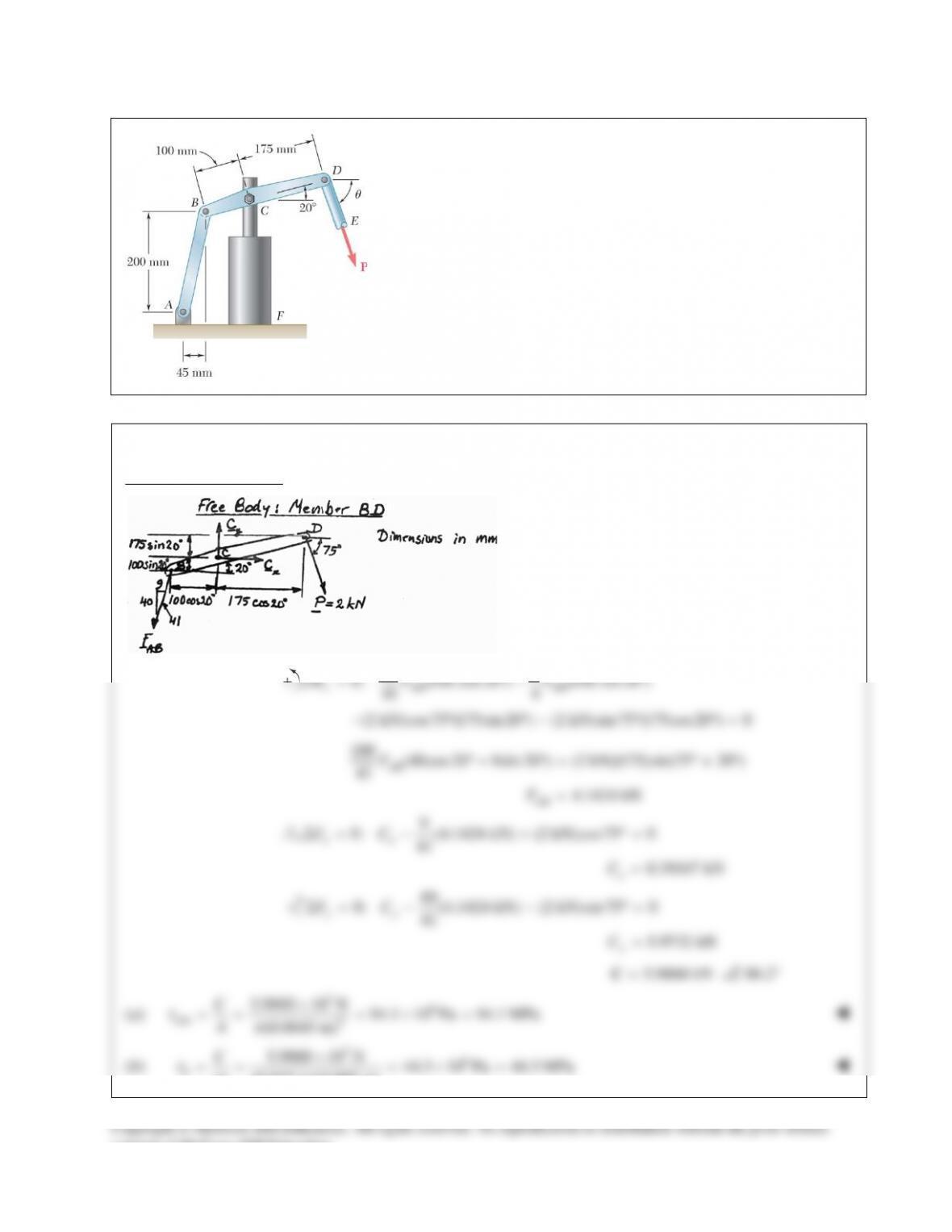
PROBLEM 8.55
The hydraulic cylinder CF, which partially controls the position of rod
DE, has been locked in the position shown. Member BD is 15 mm
thick and is connected at C to the vertical rod by a 9–mm–diameter
bolt. Knowing that P = 2 kN and
75 ,
θ
= °
determine (a) the average
shearing stress in the bolt, (b) the bearing stress at C in member BD.
SOLUTION
Free Body: Member BD.
40 9
0: (100 cos20 ) (100 sin 20 )
41 4
c AB AB
MF F
Σ = °− °
(2 kN)cos75 (175sin 20 ) (2 kN)sin75 (175cos20) 0− ° °− ° °=
100 (40cos20 9sin 20 ) (2 kN)(175)sin(75 20 )
41
4.1424 kN
AB
AB
F
F
°− ° = °+ °
=
9
0: (4.1424 kN) (2 kN)cos75 0
41
0.39167 kN
Σ = − + °=
=
xx
x
FC
C
40
0: (4.1424 kN) (2 kN)sin 75 0
41
5.9732 kN
Σ = − − °=
=
yy
y
FC
C
5.9860 kN=C
86.2°
(a)
36
ave 2
5.9860 10 N 94.1 10 Pa 94.1 MPa
(0.0045 m)
τπ
×
== =×=
C
A
(b)
36
5.9860 10 N 44.3 10 Pa 44.3 MPa
(0.015 m)(0.009 m)
bC
td
τ
×
== =×=
consent of McGraw–Hill Education.