consent of McGraw–Hill Education.
PROBLEM 12.53 (Continued)
For pipe:
11 11
(160) 80 mm, (140) 70 mm
22 22
oo ii
cd cd= = = = = =
( )
44 4 4 64
(80) (70) 13.3125 10 mm
44
oi
I cc
ππ
= −= − = ×
63 3 63
13.3125 10 166.406 10 mm 166.406 10 m
80
o
I
Sc
−
×
== =×=×
Normal stress:
36
6
5.0417 10 30.3 10 Pa
166.406 10
M
S
σ
−
×
= = = ×
×
30.3 MPa
σ
=
consent of McGraw–Hill Education.
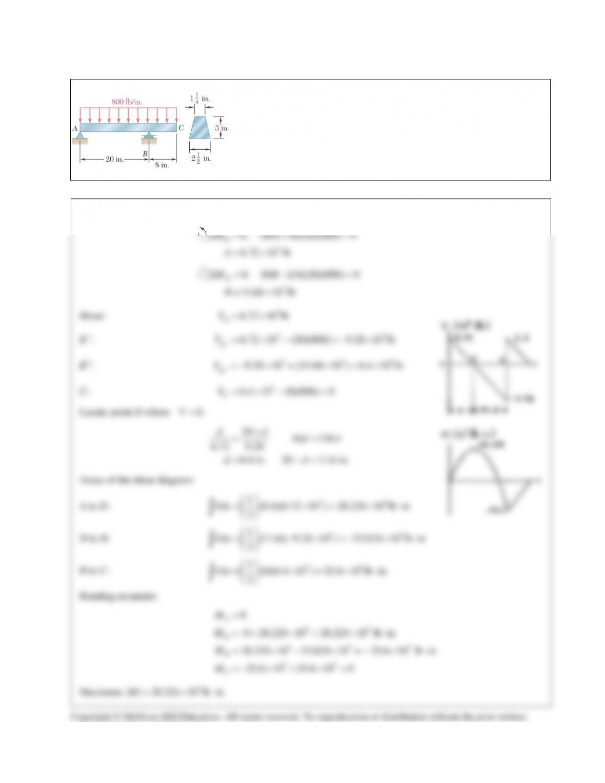
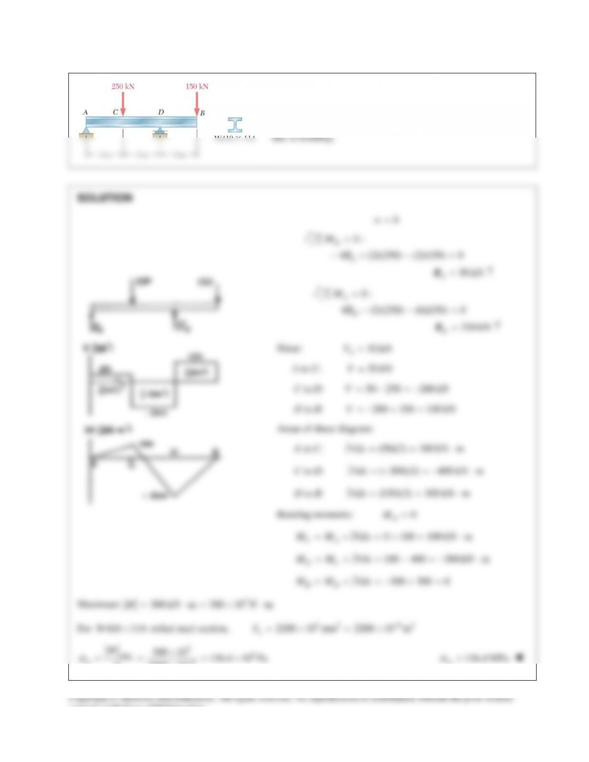
PROBLEM 12.54
Draw the shear and bending–moment diagrams for the beam and
loading shown, and determine the maximum normal stress due to
bending.
SOLUTION
3
0: 20 (6)(28)(800) 0
6.72 10 lb
B
MA
A
Σ=−+ =
= ×
3
0: 20 (14)(28)(800) 0
15.68 10 lb
A
MB
B
Σ= − =
= ×
Shear:
3
6.72 10 lb
A
V= ×
B−:
33
6.72 10 (20)(800) 9.28 10 lb
B
V
−
= ×− =− ×
B+:
3 33
9.28 10 + (15.68 10 ) 6.4 10 lb
B
V
+
=−× × =×
C:
3
6.4 10 (8)(800) 0
C
V=×− =
Locate point D where
0.V=
20 16 134.4
6.72 9.28
8.4 in. 20 11.6 in.
dd
d
dd
−
= =
= −=
Areas of the shear diagram:
A to D:
33
1(8.4)(6.72 10 ) 28.224 10 lb in
2
Vdx
= ×= × ⋅
∫
D to B:
33
1(11.6)( 9.28 10 ) 53.824 10 lb in
2
Vdx
= −× =− × ⋅
∫
B to C:
33
1(8)(6.4 10 ) 25.6 10 lb in
2
Vdx
= ×=× ⋅
∫
Bending moments:
33
3 33
33
0
0 28.224 10 28.224 10 lb in
28.224 10 53.824 10 = 25.6 10 lb in
25.6 10 25.6 10 0
A
D
B
C
M
M
M
M
=
=+ ×= × ⋅
= ×− × − × ⋅
=− ×+ ×=
Maximum
3
| | 28.224 10 lb inM= ×⋅
Copyright © McGraw–Hill Education. All rights reserved. No reproduction or distribution without the prior written
consent of McGraw–Hill Education.
PROBLEM 12.54 (Continued)
Locate centroid of cross section. See table below.
7.5 1.3333 in.
5.625
Y= =
from bottom.
For each triangle,
3
1
36
I bh=
Moment of inertia:
2
4
1.25 2.8125 4.0625 in
I I Ad
=Σ +Σ
=+=
Normal stress:
33
(28.224 10 )(1.6667) 11.58 10 psi
4.0625
Mc
I
s
×
= = = ×
11.58 ksi
s
=
Part
2
, in
A
, in.y
3
, inAy
d, in.
24
inAd
4
inI
1.875 2 3.75 0.6667 0.8333 0.9375
3.75 1 3.75 0.3333 0.4167 1.875
Σ 5.625 7.5 1.25 2.8125
consent of McGraw–Hill Education.
PROBLEM 12.55
Draw the shear and bending–moment diagrams for the beam
and loading shown and determine the maximum normal stress
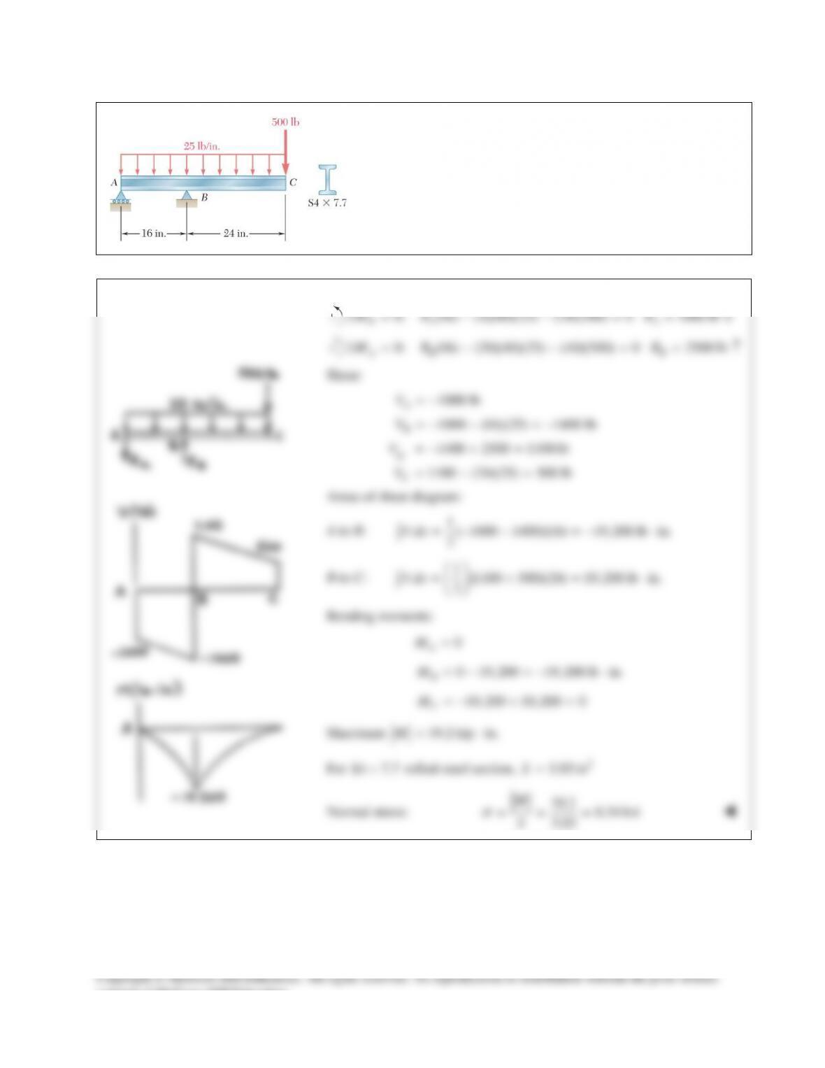
PROBLEM 12.56
Draw the shear and bending–moment diagrams for the beam and
loading shown and determine the maximum normal stress due to
bending.
SOLUTION
0: (16) (4)(40)(25) (24)(500) 0 1000 lb
BA A
MR RΣ= − − = = ↓
0: (16) (20)(40)(25) (40)(500) 0 2500 lb
AB B
MR R
Σ= − − = = ↑
Shear:
1000 lb
A
V= −
1000 (16)(25) 1400 lb
B
V=−− =−
1400 2500 1100 lb
B
V
+
=−+ =
1100 (24)(25) 500 lb
C
V=−=
Areas of shear diagram:
A to B:
1( 1000 1400)(16) 19,200 lb in.
2
V dx =−− =− ⋅
∫
B to C:
1(1100 500)(24) 19,200 lb in.
2
V dx
= += ⋅
∫
Bending moments:
0
A
M=
0 19,200 19,200 lb in.
B
M=−=− ⋅
19,200 19,200 0
C
M=−+ =
Maximum
19.2 kip in.M= ⋅
For
S4 7.7×
rolled–steel section,
3
3.03 inS=
Normal stress:
19.2 6.34 ksi
3.03
M
S
s
= = =
consent of McGraw–Hill Education.
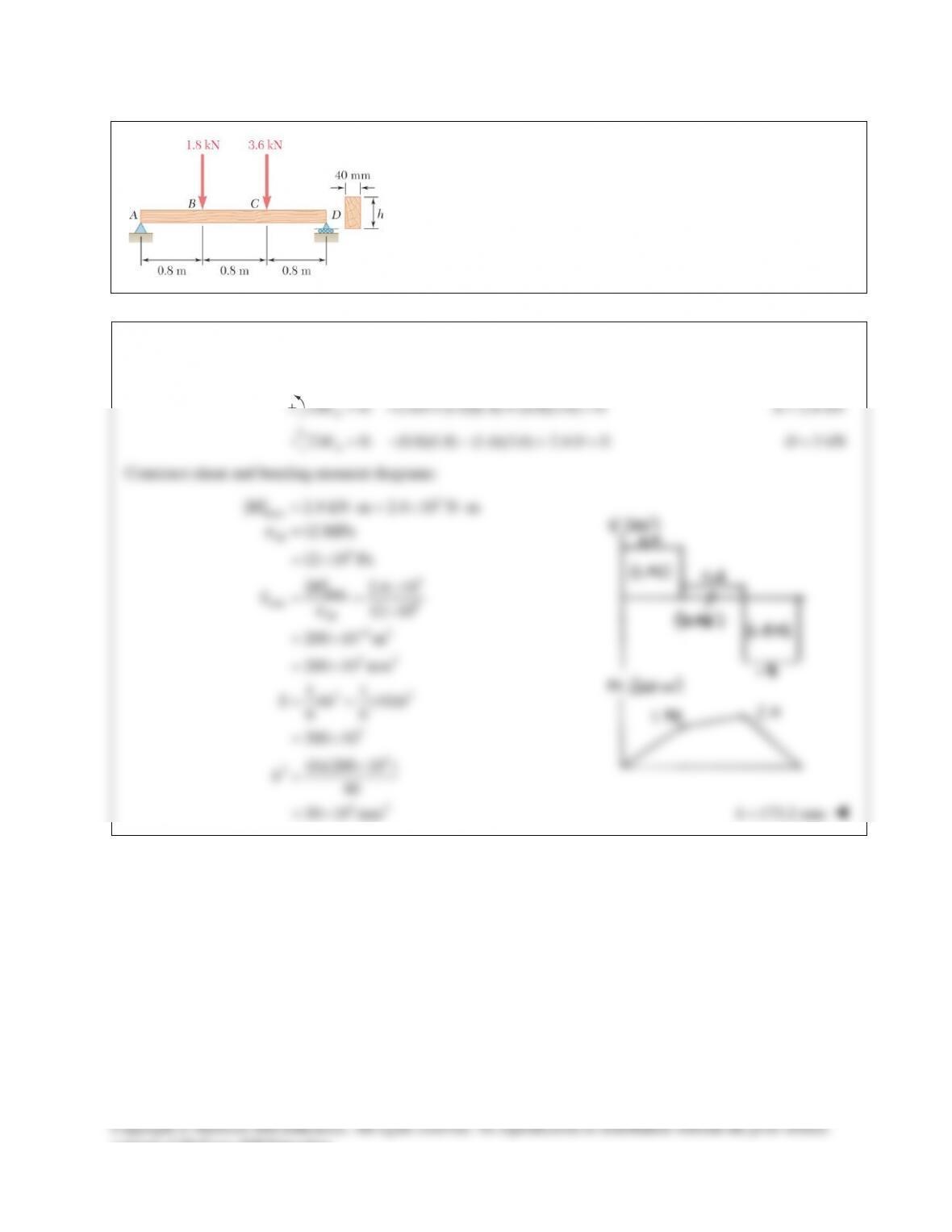
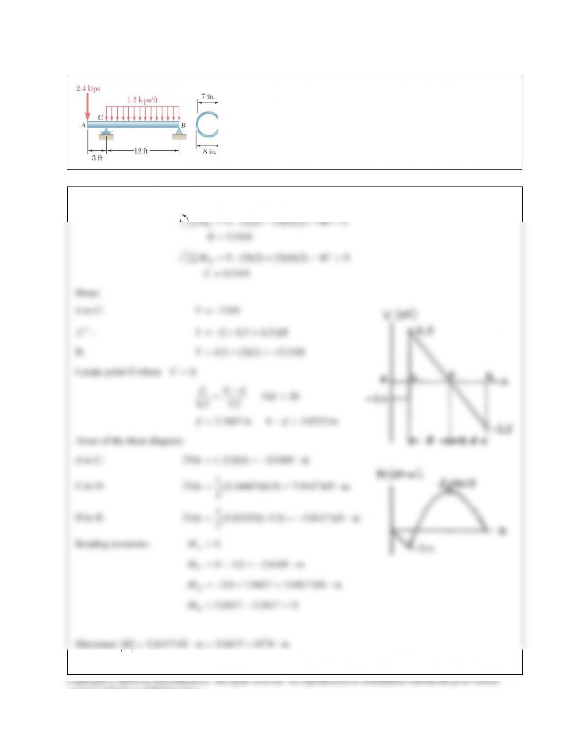
PROBLEM 12.57
For the beam and loading shown, design the cross section of the
beam, knowing that the grade of timber used has an allowable
normal stress of 12 MPa.
SOLUTION
Reactions:
0: 2.4 (1.6)(1.8) (0.8)(3.6) 0
D
MAΣ=− + + =
2.4 kNA=
0: (0.8)(1.8) (1.6)(3.6) 2.4 0
A
MDΣ= − − + =
3 kND=
Construct shear and bending moment diagrams:
3
max
| | 2.4 kN m 2.4 10 N mM= ⋅= × ⋅
all
6
3
max
min 6
all
63
33
22
3
3
2
12 MPa
12 10 Pa
|| 2.4 10
12 10
200 10 m
200 10 mm
11
(40)
66
200 10
(6)(200 10 )
40
M
S
S bh h
h
σ
σ
−
=
= ×
×
= = ×
= ×
= ×
= =
= ×
×
=
32
30 10 mm= ×
173.2 mmh=
consent of McGraw–Hill Education.
PROBLEM 12.58
For the beam and loading shown, design the cross section of the
beam, knowing that the grade of timber used has an allowable normal
stress of 12 MPa.
SOLUTION
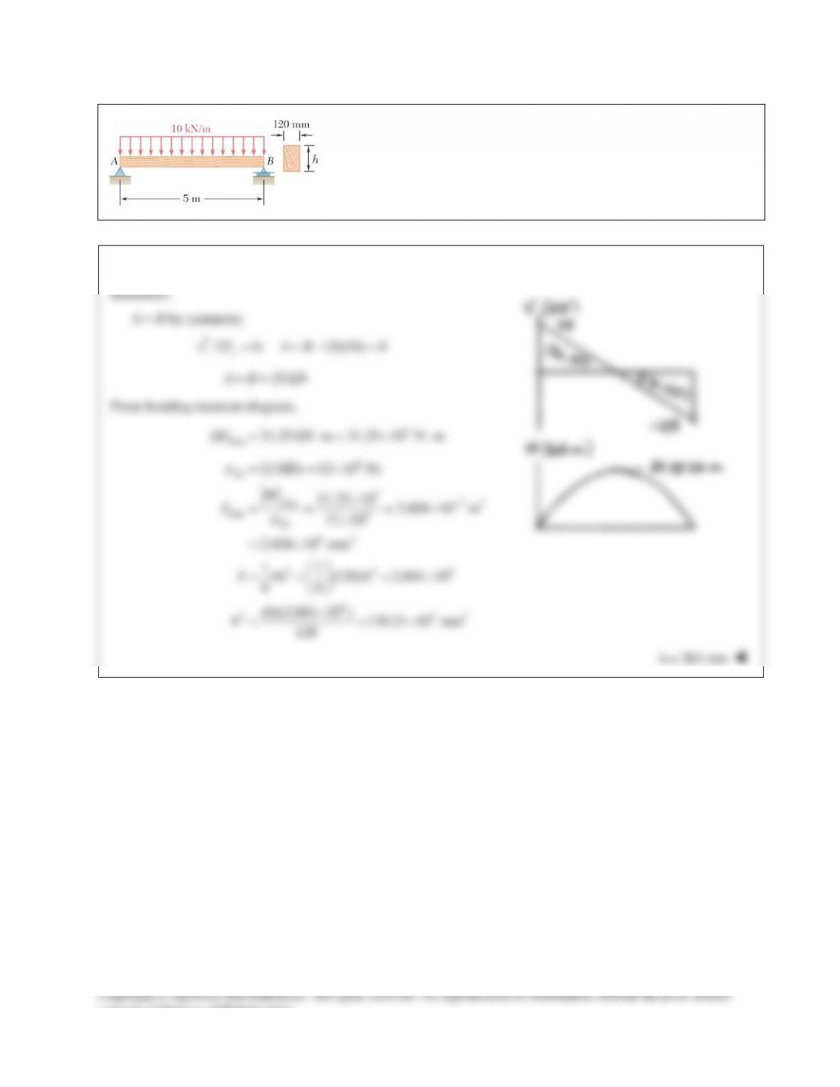
PROBLEM 12.59
For the beam and loading shown, design the cross section of the
beam, knowing that the grade of timber used has an allowable
consent of McGraw–Hill Education.

PROBLEM 12.53 (Continued)
For pipe:
11 11
(160) 80 mm, (140) 70 mm
22 22
oo ii
cd cd= = = = = =
( )
44 4 4 64
(80) (70) 13.3125 10 mm
44
oi
I cc
ππ
= −= − = ×
63 3 63
13.3125 10 166.406 10 mm 166.406 10 m
80
o
I
Sc
−
×
== =×=×
Normal stress:
36
6
5.0417 10 30.3 10 Pa
166.406 10
M
S
σ
−
×
= = = ×
×
30.3 MPa
σ
=
consent of McGraw–Hill Education.
PROBLEM 12.54
Draw the shear and bending–moment diagrams for the beam and
loading shown, and determine the maximum normal stress due to
bending.
SOLUTION
3
0: 20 (6)(28)(800) 0
6.72 10 lb
B
MA
A
Σ=−+ =
= ×
3
0: 20 (14)(28)(800) 0
15.68 10 lb
A
MB
B
Σ= − =
= ×
Shear:
3
6.72 10 lb
A
V= ×
B−:
33
6.72 10 (20)(800) 9.28 10 lb
B
V
−
= ×− =− ×
B+:
3 33
9.28 10 + (15.68 10 ) 6.4 10 lb
B
V
+
=−× × =×
C:
3
6.4 10 (8)(800) 0
C
V=×− =
Locate point D where
0.V=
20 16 134.4
6.72 9.28
8.4 in. 20 11.6 in.
dd
d
dd
−
= =
= −=
Areas of the shear diagram:
A to D:
33
1(8.4)(6.72 10 ) 28.224 10 lb in
2
Vdx
= ×= × ⋅
∫
D to B:
33
1(11.6)( 9.28 10 ) 53.824 10 lb in
2
Vdx
= −× =− × ⋅
∫
B to C:
33
1(8)(6.4 10 ) 25.6 10 lb in
2
Vdx
= ×=× ⋅
∫
Bending moments:
33
3 33
33
0
0 28.224 10 28.224 10 lb in
28.224 10 53.824 10 = 25.6 10 lb in
25.6 10 25.6 10 0
A
D
B
C
M
M
M
M
=
=+ ×= × ⋅
= ×− × − × ⋅
=− ×+ ×=
Maximum
3
| | 28.224 10 lb inM= ×⋅
Copyright © McGraw–Hill Education. All rights reserved. No reproduction or distribution without the prior written
consent of McGraw–Hill Education.
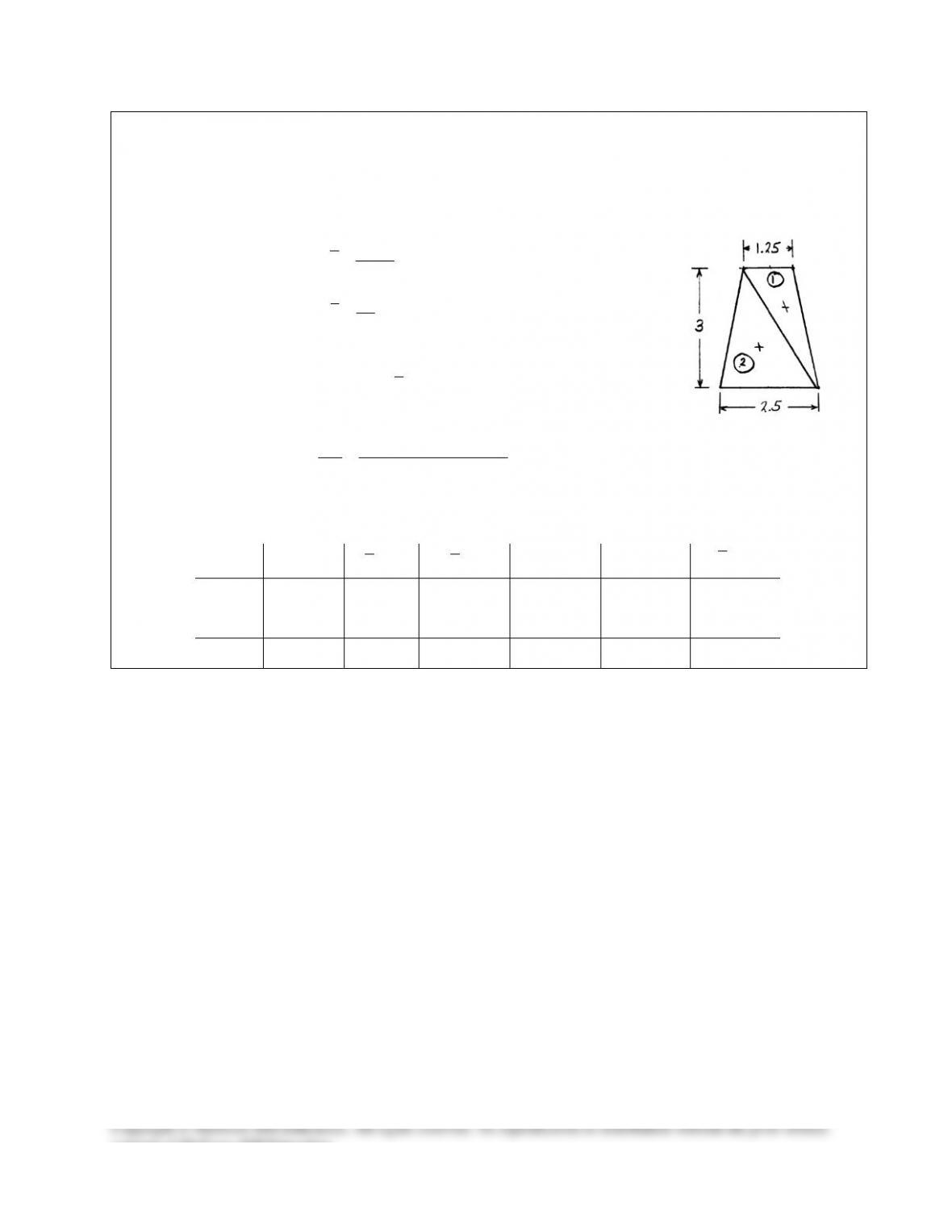
PROBLEM 12.54 (Continued)
Locate centroid of cross section. See table below.
7.5 1.3333 in.
5.625
Y= =
from bottom.
For each triangle,
3
1
36
I bh=
Moment of inertia:
2
4
1.25 2.8125 4.0625 in
I I Ad
=Σ +Σ
=+=
Normal stress:
33
(28.224 10 )(1.6667) 11.58 10 psi
4.0625
Mc
I
s
×
= = = ×
11.58 ksi
s
=
Part
2
, in
A
, in.y
3
, inAy
d, in.
24
inAd
4
inI
1.875 2 3.75 0.6667 0.8333 0.9375
3.75 1 3.75 0.3333 0.4167 1.875
Σ 5.625 7.5 1.25 2.8125
consent of McGraw–Hill Education.
PROBLEM 12.55
Draw the shear and bending–moment diagrams for the beam
and loading shown and determine the maximum normal stress
PROBLEM 12.56
Draw the shear and bending–moment diagrams for the beam and
loading shown and determine the maximum normal stress due to
bending.
SOLUTION
0: (16) (4)(40)(25) (24)(500) 0 1000 lb
BA A
MR RΣ= − − = = ↓
0: (16) (20)(40)(25) (40)(500) 0 2500 lb
AB B
MR R
Σ= − − = = ↑
Shear:
1000 lb
A
V= −
1000 (16)(25) 1400 lb
B
V=−− =−
1400 2500 1100 lb
B
V
+
=−+ =
1100 (24)(25) 500 lb
C
V=−=
Areas of shear diagram:
A to B:
1( 1000 1400)(16) 19,200 lb in.
2
V dx =−− =− ⋅
∫
B to C:
1(1100 500)(24) 19,200 lb in.
2
V dx
= += ⋅
∫
Bending moments:
0
A
M=
0 19,200 19,200 lb in.
B
M=−=− ⋅
19,200 19,200 0
C
M=−+ =
Maximum
19.2 kip in.M= ⋅
For
S4 7.7×
rolled–steel section,
3
3.03 inS=
Normal stress:
19.2 6.34 ksi
3.03
M
S
s
= = =
consent of McGraw–Hill Education.
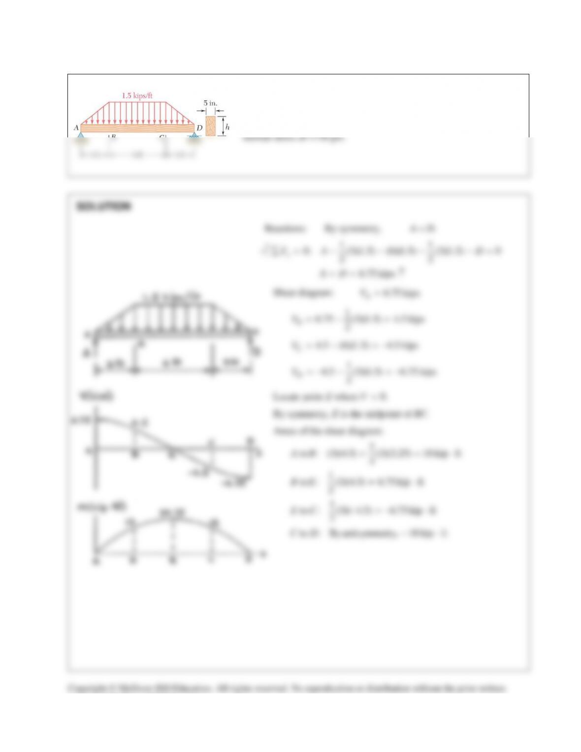
PROBLEM 12.57
For the beam and loading shown, design the cross section of the
beam, knowing that the grade of timber used has an allowable
normal stress of 12 MPa.
SOLUTION
Reactions:
0: 2.4 (1.6)(1.8) (0.8)(3.6) 0
D
MAΣ=− + + =
2.4 kNA=
0: (0.8)(1.8) (1.6)(3.6) 2.4 0
A
MDΣ= − − + =
3 kND=
Construct shear and bending moment diagrams:
3
max
| | 2.4 kN m 2.4 10 N mM= ⋅= × ⋅
all
6
3
max
min 6
all
63
33
22
3
3
2
12 MPa
12 10 Pa
|| 2.4 10
12 10
200 10 m
200 10 mm
11
(40)
66
200 10
(6)(200 10 )
40
M
S
S bh h
h
σ
σ
−
=
= ×
×
= = ×
= ×
= ×
= =
= ×
×
=
32
30 10 mm= ×
173.2 mmh=
consent of McGraw–Hill Education.
PROBLEM 12.58
For the beam and loading shown, design the cross section of the
beam, knowing that the grade of timber used has an allowable normal
stress of 12 MPa.
SOLUTION
PROBLEM 12.59
For the beam and loading shown, design the cross section of the
beam, knowing that the grade of timber used has an allowable
consent of McGraw–Hill Education.