consent of McGraw–Hill Education.
consent of McGraw–Hill Education.
SOLUTION Continued
consent of McGraw–Hill Education.
PROBLEM 10.49
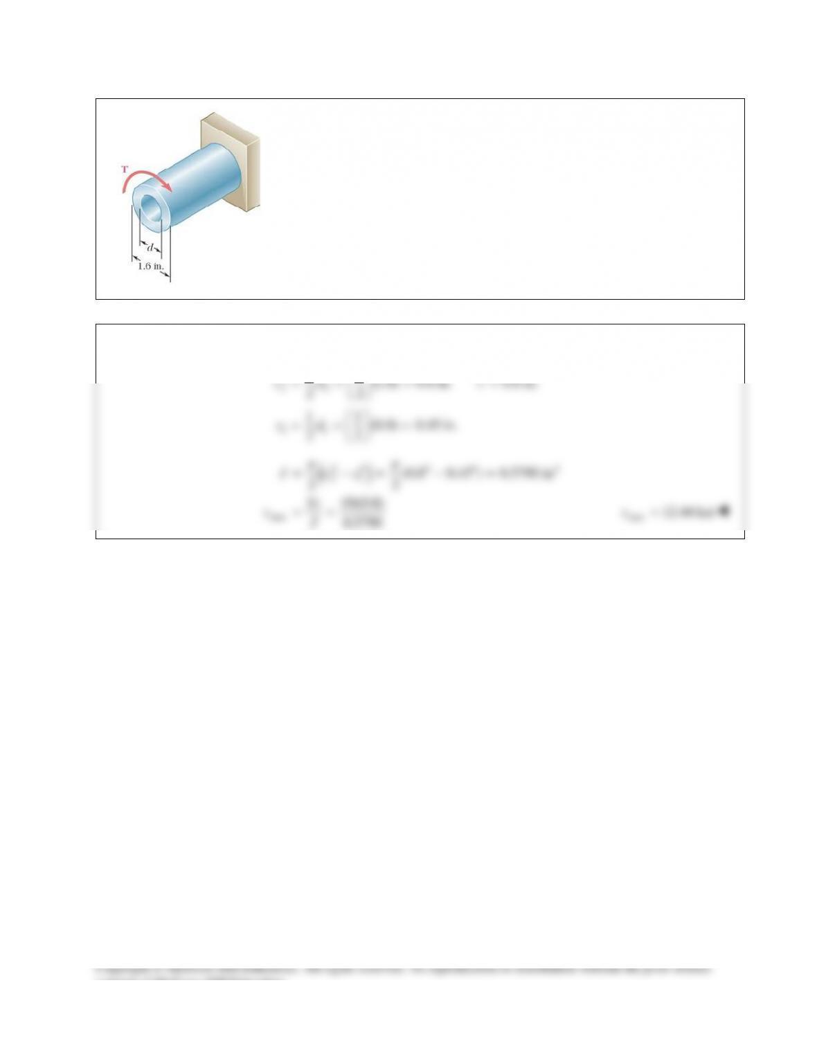
Knowing that the internal diameter of the hollow shaft shown is
0.9in.,d=
determine the maximum shearing stress caused by a torque of magnitude
9kip in.T= ⋅
SOLUTION
22
11
11
(1.6) 0.8 in. 0.8 in.
22
11
(0.9) 0.45 in.
22
cd c
cd
= = = =
= = =
( )
44 4 4 4
21
max
(0.8 0.45 ) 0.5790 in
22
(9)(0.8)
0.5790
J cc
Tc
J
ππ
τ
= −= − =
= =
max 12.44 ksi
τ
=
consent of McGraw–Hill Education.
PROBLEM 10.50
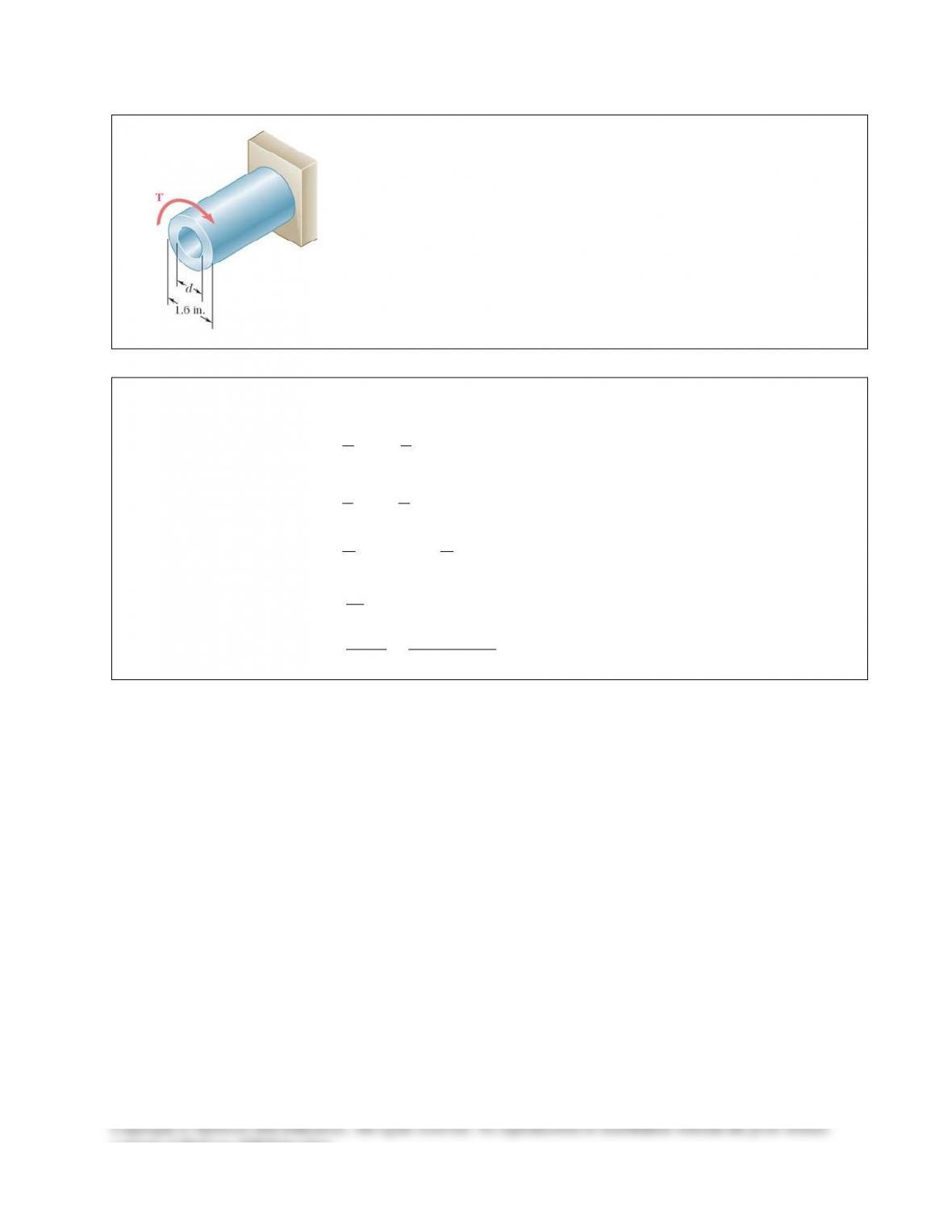
Knowing that
1.2 in.,d=
determine the torque T that causes a maximum
shearing stress of 7.5 ksi in the hollow shaft shown.
SOLUTION
22
11
(1.6) 0.8 in.
22
cd
= = =
0.8 in.c=
( )
11
44 4 4 4
21
11
(1.2) 0.6 in.
22
(0.8 0.6 ) 0.4398 in
22
cd
J cc
ππ
= = =
= −= − =
max
max
(0.4398)(7.5)
0.8
Tc
J
J
Tc
τ
τ
=
= =
4.12 kip inT= ⋅
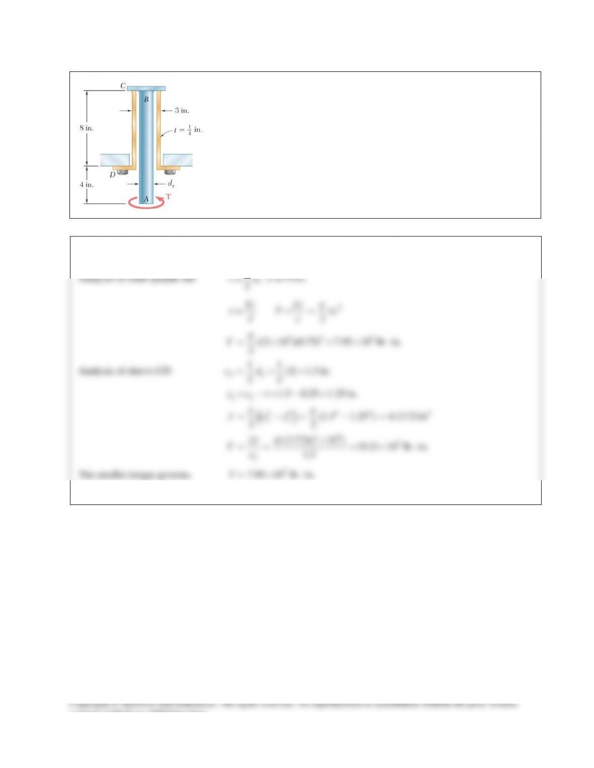
PROBLEM 10.51
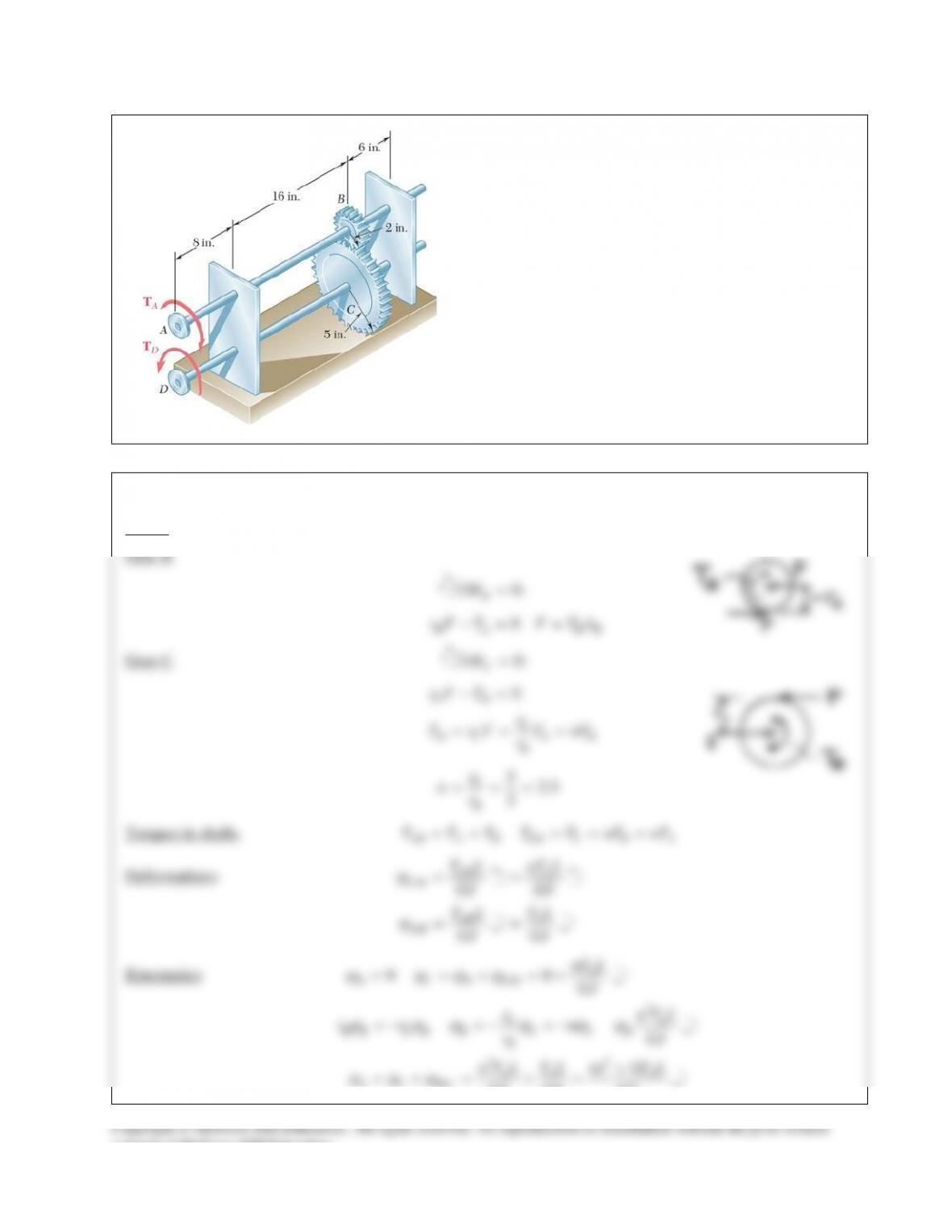
The solid spindle AB has a diameter ds = 1.5 in. and is made of a steel with
an allowable shearing stress of 12 ksi, while sleeve CD is made of a brass
with an allowable shearing stress of 7 ksi. Determine the largest torque T that
can be applied at A.
SOLUTION
10.75 in.
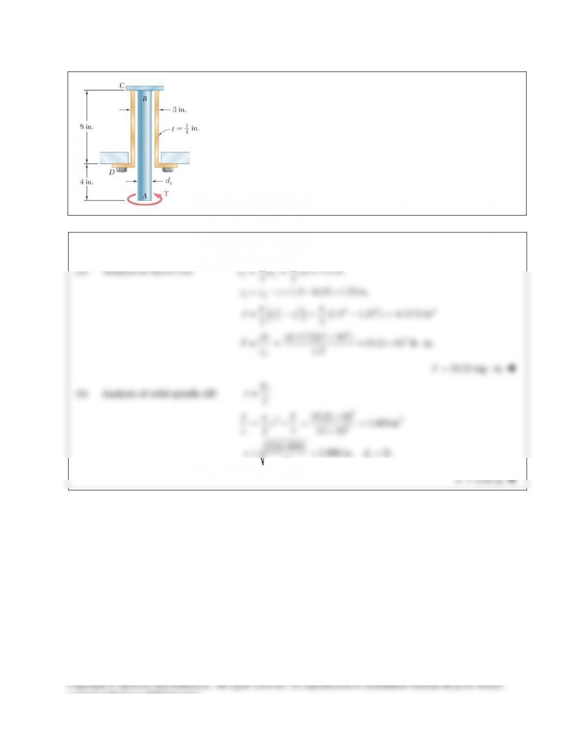
PROBLEM 10.52
The solid spindle AB is made of a steel with an allowable shearing stress of
12 ksi, and sleeve CD is made of a brass with an allowable shearing stress of
7 ksi. Determine (a) the largest torque T that can be applied at A if the
allowable shearing stress is not to be exceeded in sleeve CD, (b) the
corresponding required value of the diameter
s
d
of spindle AB.
SOLUTION
(a) Analysis of sleeve CD:
()
2
12
44 4 4 4
21
33
2
11
(3) 1.5 in.
22
1.5 0.25 1.25 in.
= (1.5 1.25 ) 4.1172 in
22
(4.1172)(7 10 )
= 19.21 10 lb in.
1.5
o
cd
cct
J cc
J
Tc
ππ
t
= = =
= −= − =
−= − =
×
= =×⋅
19.21 kip in.T= ⋅
(b) Analysis of solid spindle AB:
3
33
3
3
=
19.21 10 1.601in
212 10
(2)(1.601) 1.006 in. 2
s
Tc
J
JT
c
c
c dc
t
π
t
π
×
= = = =
×
= = =
2.01 in.=d
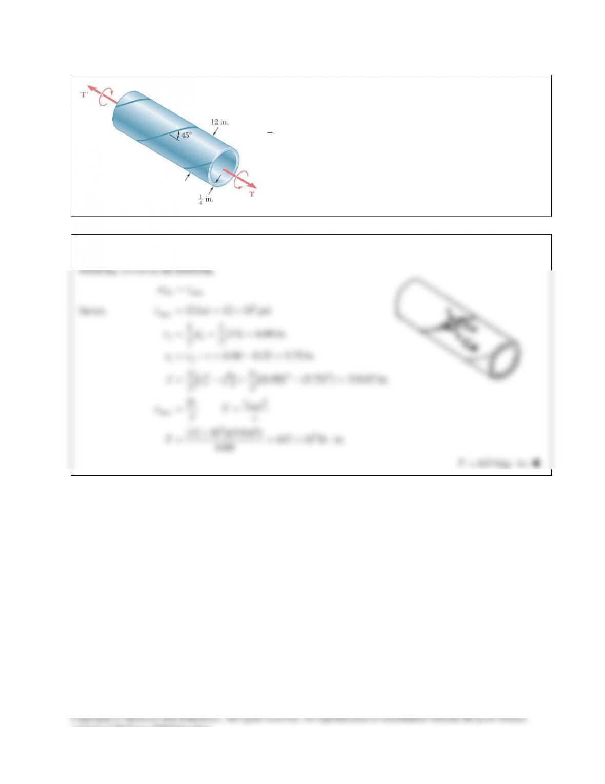
PROBLEM 10.53
A steel pipe of 12–in. outer diameter is fabricated from
1
4
-in.
–thick plate by welding along a helix which forms an angle
of 45° with a plane perpendicular to the axis of the pipe.
Knowing that the maximum allowable tensile stress in the weld
is 12 ksi, determine the largest torque that can be applied to the
pipe.
SOLUTION
consent of McGraw–Hill Education.
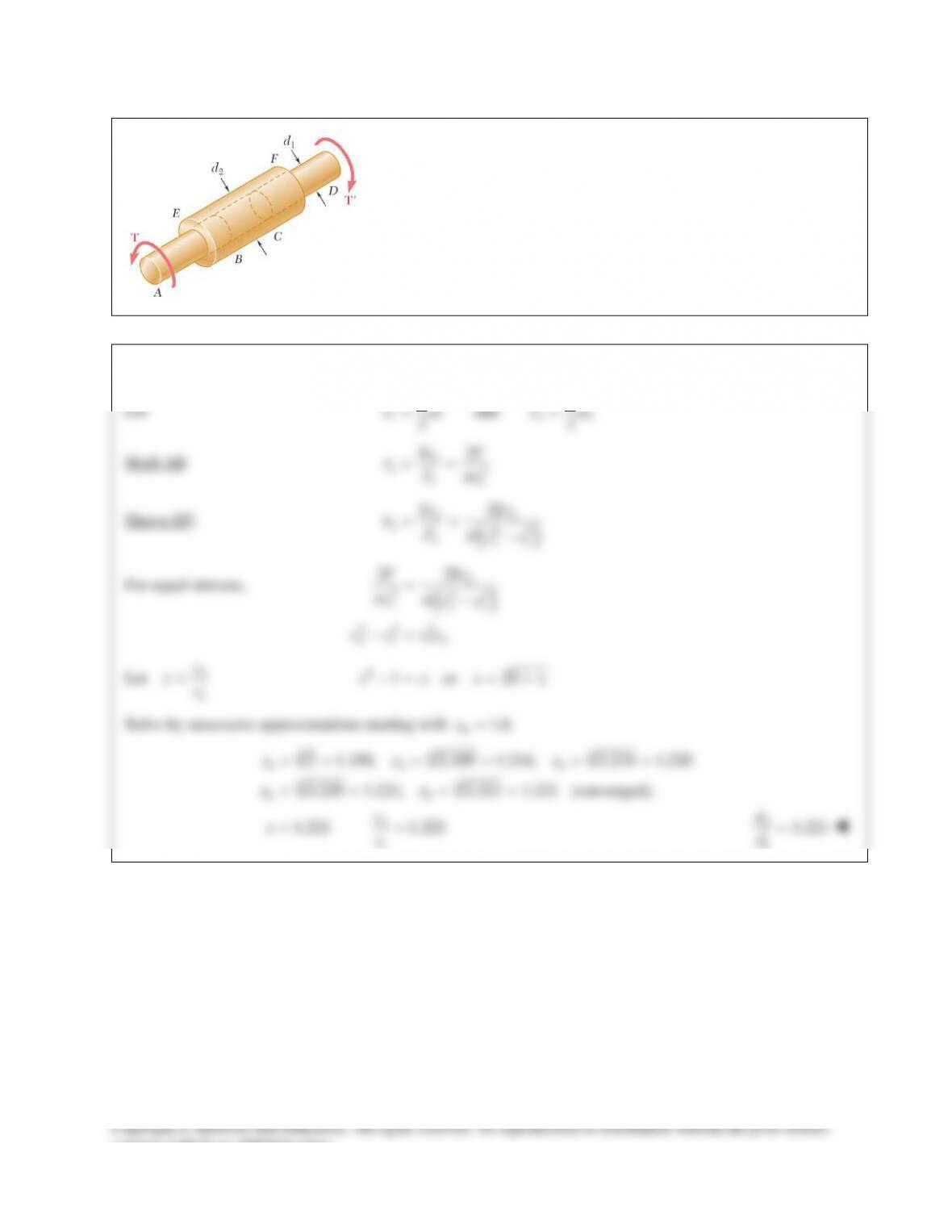
PROBLEM 10.54
Two solid brass rods AB and CD are brazed to a brass sleeve EF.
Determine the ratio
21
/
dd
for which the same maximum shearing stress
occurs in the rods and in the sleeve.
SOLUTION
Let
11 2 2
11
and
22
cd cd= =
Shaft AB:
1
13
11
2Tc T
Jc
τπ
= =
Sleeve EF:
()
22
244
221
2Tc Tc
Jcc
τπ
= = −
For equal stresses,
( )
2
344
121
44 3
2 1 12
22T Tc
ccc
c c cc
ππ
=−
−=
Let
2
1
c
xc
=
44
1 or 1x xx x−= = +
Solve by successive approximations starting with
0
1.0.x=
444
12 3
44
45
2
1
2 1.189, 2.189 1.216, 2.216 1.220
2.220 1.221, 2.221 1.221 (converged).
1.221 1.221
xx x
xx
c
xc
= = = = = =
= = = =
= =
2
1
1.221
d
d=
consent of McGraw–Hill Education.
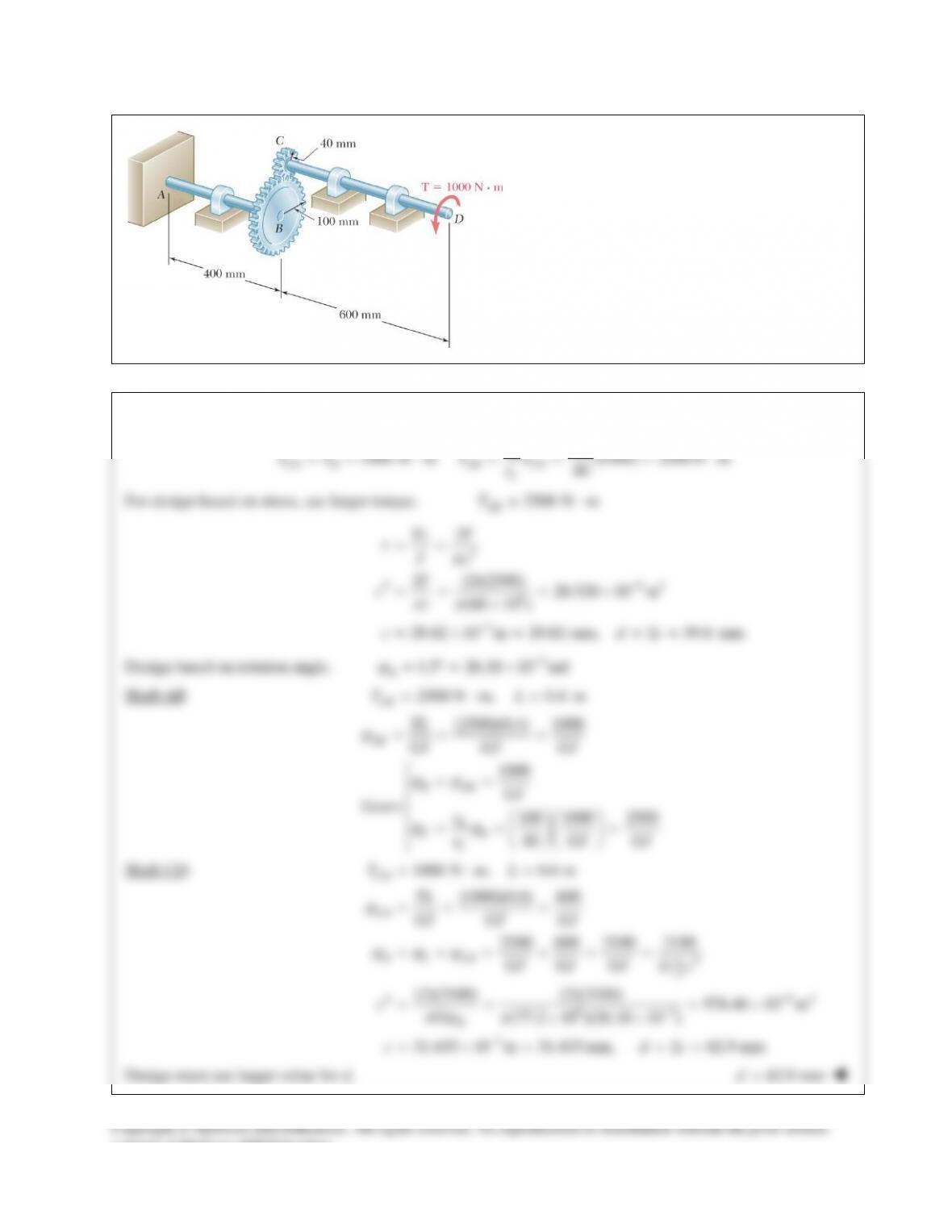
PROBLEM 10.55
The design of the gear–and–shaft system shown
requires that steel shafts of the same diameter be
used for both AB and CD. It is further required
that
max 60 MPa,
τ
≤
and that the angle
D
φ
through
which end D of shaft CD rotates not exceed 1.5°.
Knowing that G = 77.2 GPa, determine the
required diameter of the shafts.
SOLUTION
100
1000 N m (1000) 2500N m
40
B
CD D AB CD
C
r
TT T T
r
==⋅== =⋅
For design based on stress, use larger torque.
2500 N m
AB
T= ⋅
3
3 63
6
3
2
2 (2)(2500) 26.526 10 m
(60 10 )
29.82 10 m 29.82 mm, 2 59.6 mm
Tc T
Jc
T
c
c dc
τπ
πτ π
−
−
= =
= = = ×
×
=×= ==
Design based on rotation angle.
3
1.5 26.18 10 rad
D
ϕ
−
= °= ×
Shaft AB:
2500 N m, 0.4 m
AB
TL= ⋅=
(2500)(0.4) 1000
1000
100 1000 2500
40
AB
B AB
B
CB
C
TL
GJ GJ GJ
GJ
Gears r
r GJ GJ
ϕ
ϕϕ
ϕϕ
= = =
= =
= = =
Shaft CD:
1000 N m, 0.6 m
CD
TL= ⋅=
4
2
4 94
93
3
(1000)(0.6) 600
2500 600 3100 3100
(2)(3100) (2)(3100) 976.46 10 m
(77.2 10 )(26.18 10 )
31.435 10 m 31.435 mm, 2 62.9 mm
π
ϕ
ϕ ϕϕ
πϕ π
−
−
−
= = =
=+= += =
= = = ×
××
=×= ==
CD
D C CD
D
TL
GJ GJ GJ
GJ GJ GJ Gc
cG
c dc
Design must use larger value for d.
62.9 mmd=
consent of McGraw–Hill Education.
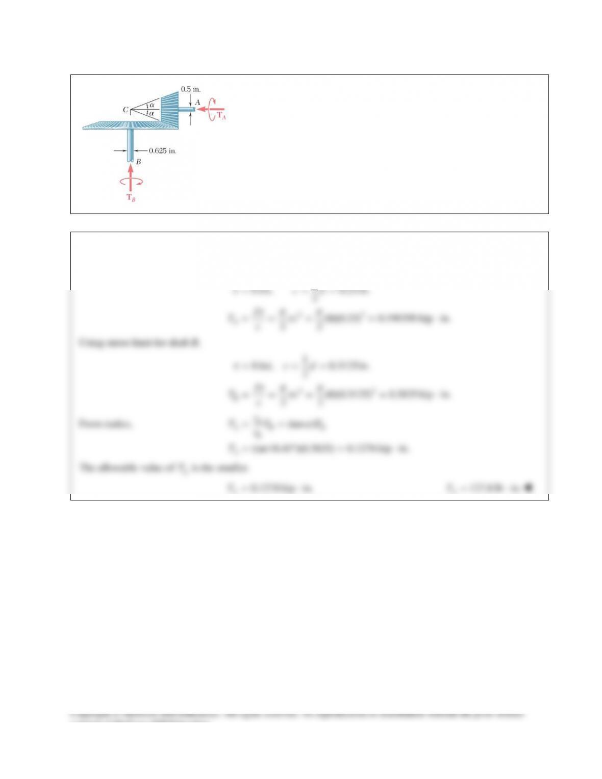
PROBLEM 10.56
In the bevel–gear system shown,
18.43 .
α
= °
Knowing that the
allowable shearing stress is 8 ksi in each shaft and that the system is in
equilibrium, determine the largest torque
A
T
that can be applied at A.
SOLUTION
Using stress limit for shaft A,
33
1
8 ksi, 0.25 in.
2
(8)(0.25) 0.196350 kip in.
22
A
cd
J
Tc
c
τ
τp p
τ
= = =
= = = = ⋅
Using stress limit for shaft B,
33
1
8 ksi, 0.3125 in.
2
(8)(0.3125) 0.3835 kip in.
22
τ
τp p
τ
= = =
= = = = ⋅
B
cd
J
Tc
c
From statics,
(tan )
(tan18.43 )(0.3835) 0.1278 kip in.
A
AB B
B
A
r
TT T
r
T
α
= =
= °= ⋅
The allowable value of
A
T
is the smaller.
0.1278 kip in.
A
T= ⋅
127.8 lb in.
A
T= ⋅
consent of McGraw–Hill Education.
SOLUTION Continued
consent of McGraw–Hill Education.
PROBLEM 10.49
Knowing that the internal diameter of the hollow shaft shown is
0.9in.,d=
determine the maximum shearing stress caused by a torque of magnitude
9kip in.T= ⋅
SOLUTION
22
11
11
(1.6) 0.8 in. 0.8 in.
22
11
(0.9) 0.45 in.
22
cd c
cd
= = = =
= = =
( )
44 4 4 4
21
max
(0.8 0.45 ) 0.5790 in
22
(9)(0.8)
0.5790
J cc
Tc
J
ππ
τ
= −= − =
= =
max 12.44 ksi
τ
=
consent of McGraw–Hill Education.
PROBLEM 10.50
Knowing that
1.2 in.,d=
determine the torque T that causes a maximum
shearing stress of 7.5 ksi in the hollow shaft shown.
SOLUTION
22
11
(1.6) 0.8 in.
22
cd
= = =
0.8 in.c=
( )
11
44 4 4 4
21
11
(1.2) 0.6 in.
22
(0.8 0.6 ) 0.4398 in
22
cd
J cc
ππ
= = =
= −= − =
max
max
(0.4398)(7.5)
0.8
Tc
J
J
Tc
τ
τ
=
= =
4.12 kip inT= ⋅
PROBLEM 10.51
The solid spindle AB has a diameter ds = 1.5 in. and is made of a steel with
an allowable shearing stress of 12 ksi, while sleeve CD is made of a brass
with an allowable shearing stress of 7 ksi. Determine the largest torque T that
can be applied at A.
SOLUTION
10.75 in.
PROBLEM 10.52
The solid spindle AB is made of a steel with an allowable shearing stress of
12 ksi, and sleeve CD is made of a brass with an allowable shearing stress of
7 ksi. Determine (a) the largest torque T that can be applied at A if the
allowable shearing stress is not to be exceeded in sleeve CD, (b) the
corresponding required value of the diameter
s
d
of spindle AB.
SOLUTION
(a) Analysis of sleeve CD:
()
2
12
44 4 4 4
21
33
2
11
(3) 1.5 in.
22
1.5 0.25 1.25 in.
= (1.5 1.25 ) 4.1172 in
22
(4.1172)(7 10 )
= 19.21 10 lb in.
1.5
o
cd
cct
J cc
J
Tc
ππ
t
= = =
= −= − =
−= − =
×
= =×⋅
19.21 kip in.T= ⋅
(b) Analysis of solid spindle AB:
3
33
3
3
=
19.21 10 1.601in
212 10
(2)(1.601) 1.006 in. 2
s
Tc
J
JT
c
c
c dc
t
π
t
π
×
= = = =
×
= = =
2.01 in.=d
PROBLEM 10.53
A steel pipe of 12–in. outer diameter is fabricated from
1
4
-in.
–thick plate by welding along a helix which forms an angle
of 45° with a plane perpendicular to the axis of the pipe.
Knowing that the maximum allowable tensile stress in the weld
is 12 ksi, determine the largest torque that can be applied to the
pipe.
SOLUTION
consent of McGraw–Hill Education.
PROBLEM 10.54
Two solid brass rods AB and CD are brazed to a brass sleeve EF.
Determine the ratio
21
/
dd
for which the same maximum shearing stress
occurs in the rods and in the sleeve.
SOLUTION
Let
11 2 2
11
and
22
cd cd= =
Shaft AB:
1
13
11
2Tc T
Jc
τπ
= =
Sleeve EF:
()
22
244
221
2Tc Tc
Jcc
τπ
= = −
For equal stresses,
( )
2
344
121
44 3
2 1 12
22T Tc
ccc
c c cc
ππ
=−
−=
Let
2
1
c
xc
=
44
1 or 1x xx x−= = +
Solve by successive approximations starting with
0
1.0.x=
444
12 3
44
45
2
1
2 1.189, 2.189 1.216, 2.216 1.220
2.220 1.221, 2.221 1.221 (converged).
1.221 1.221
xx x
xx
c
xc
= = = = = =
= = = =
= =
2
1
1.221
d
d=
consent of McGraw–Hill Education.
PROBLEM 10.55
The design of the gear–and–shaft system shown
requires that steel shafts of the same diameter be
used for both AB and CD. It is further required
that
max 60 MPa,
τ
≤
and that the angle
D
φ
through
which end D of shaft CD rotates not exceed 1.5°.
Knowing that G = 77.2 GPa, determine the
required diameter of the shafts.
SOLUTION
100
1000 N m (1000) 2500N m
40
B
CD D AB CD
C
r
TT T T
r
==⋅== =⋅
For design based on stress, use larger torque.
2500 N m
AB
T= ⋅
3
3 63
6
3
2
2 (2)(2500) 26.526 10 m
(60 10 )
29.82 10 m 29.82 mm, 2 59.6 mm
Tc T
Jc
T
c
c dc
τπ
πτ π
−
−
= =
= = = ×
×
=×= ==
Design based on rotation angle.
3
1.5 26.18 10 rad
D
ϕ
−
= °= ×
Shaft AB:
2500 N m, 0.4 m
AB
TL= ⋅=
(2500)(0.4) 1000
1000
100 1000 2500
40
AB
B AB
B
CB
C
TL
GJ GJ GJ
GJ
Gears r
r GJ GJ
ϕ
ϕϕ
ϕϕ
= = =
= =
= = =
Shaft CD:
1000 N m, 0.6 m
CD
TL= ⋅=
4
2
4 94
93
3
(1000)(0.6) 600
2500 600 3100 3100
(2)(3100) (2)(3100) 976.46 10 m
(77.2 10 )(26.18 10 )
31.435 10 m 31.435 mm, 2 62.9 mm
π
ϕ
ϕ ϕϕ
πϕ π
−
−
−
= = =
=+= += =
= = = ×
××
=×= ==
CD
D C CD
D
TL
GJ GJ GJ
GJ GJ GJ Gc
cG
c dc
Design must use larger value for d.
62.9 mmd=
consent of McGraw–Hill Education.
PROBLEM 10.56
In the bevel–gear system shown,
18.43 .
α
= °
Knowing that the
allowable shearing stress is 8 ksi in each shaft and that the system is in
equilibrium, determine the largest torque
A
T
that can be applied at A.
SOLUTION
Using stress limit for shaft A,
33
1
8 ksi, 0.25 in.
2
(8)(0.25) 0.196350 kip in.
22
A
cd
J
Tc
c
τ
τp p
τ
= = =
= = = = ⋅
Using stress limit for shaft B,
33
1
8 ksi, 0.3125 in.
2
(8)(0.3125) 0.3835 kip in.
22
τ
τp p
τ
= = =
= = = = ⋅
B
cd
J
Tc
c
From statics,
(tan )
(tan18.43 )(0.3835) 0.1278 kip in.
A
AB B
B
A
r
TT T
r
T
α
= =
= °= ⋅
The allowable value of
A
T
is the smaller.
0.1278 kip in.
A
T= ⋅
127.8 lb in.
A
T= ⋅