consent of McGraw–Hill Education.
PROBLEM 10.57
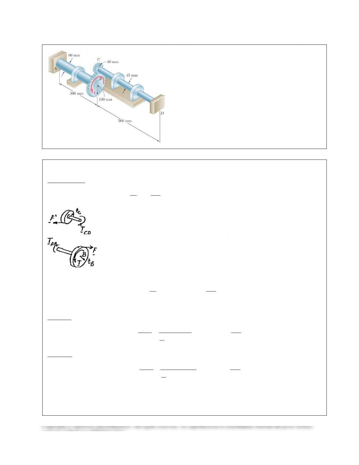
Ends A and D of the two solid steel shafts AB and CD are
fixed, while ends B and C are connected to gears as shown.
Knowing that the allowable shearing stress is 50 MPa in
each shaft, determine the largest torque T that may be
applied to gear B.
SOLUTION
2
Shaft CD:
0.5 m, 0.0225 mLc= =
3
/4
(0.5) 1242 10
(0.0225)
2
φφ π
= = = = ×
CD CD CD
C CD TL T T
JG G
G
(6)
SOLUTION Continued
PROBLEM 10.58
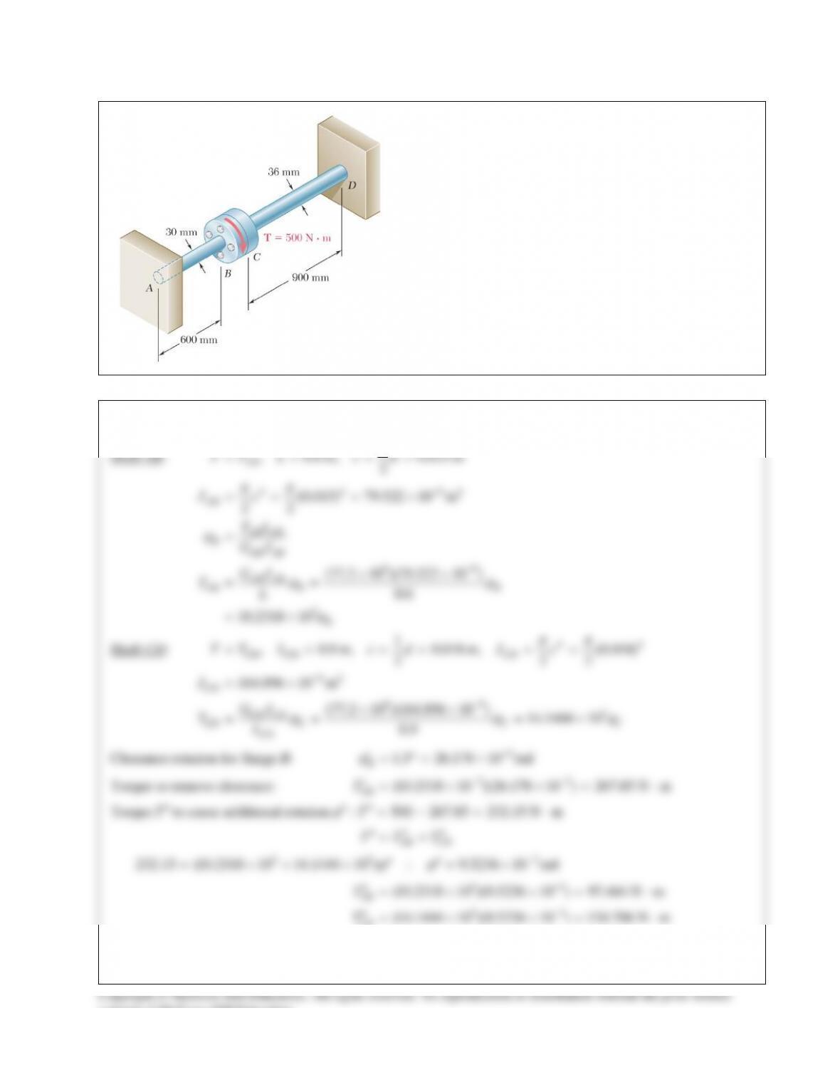
Two solid steel shafts are fitted with flanges that are then
connected by bolts as shown. The bolts are slightly
undersized and permit a 1.5° rotation of one flange with
respect to the other before the flanges begin to rotate as a
single unit. Knowing that G = 77.2 GPa, determine the
maximum shearing stress in each shaft when a torque of T
of magnitude 500 N ⋅ m is applied to the flange indicated.
The torque T is applied to flange B.
SOLUTION
Shaft AB:
4 4 94
99
3
1
, 0.6 m, 0.015 m
2
(0.015) 79.522 10 m
22
(77.2 10 )(79.522 10 )
0.6
10.2318 10
ππ
ϕ
ϕϕ
ϕ
−
−
= = = =
= = = ×
=
××
= =
= ×
AB
AB
AB AB
BAB AB
AB AB
AB B B
B
TT L c d
Jc
TL
GJ
GJ
TL
Shaft CD:
44
94
99 3
1
, 0.9 m, 0.018 m, (0.018)
2 22
164.896 10 m
77.2 10 )(164.896 10 ) 14.1444 10
0.9
ππ
ϕ ϕϕ
−
−
= = = = = =
= ×
(× ×
= = = ×
CD CD CD
CD
CD CD
CD C C C
CD
TT L c d J c
J
GJ
TL
Clearance rotation for flange B:
3
1.5 26.178 10 rad
B
ϕ
−
′= °= ×
Torque to remove clearance:
33
(10.2318 10 )(26.178 10 ) 267.85 N m
AB
T
−−
′= × ×= ⋅
Torque
T′′
to cause additional rotation
: 500 267.85 232.15 N mT
ϕ
′′ ′′ =−= ⋅
AB CD
TT T
′′ ′′ ′′
= +
33 3
232.15 (10.2318 10 14.1444 10 ) 9.5236 10 rad
ϕϕ
−
′′ ′′
= ×+ × ∴ = ×
33
33
(10.2318 10 )(9.5236 10 ) 97.444 N m
AB
T
−
−
′′ = × ×= ⋅
SOLUTION Continued

PROBLEM 10.59
Two solid steel shafts are fitted with flanges that are then
connected by bolts as shown. The bolts are slightly
undersized and permit a 1.5° rotation of one flange with
respect to the other before the flanges begin to rotate as a
single unit. Knowing that G = 77.2 GPa, determine the
maximum shearing stress in each shaft when a torque of T
of magnitude 500 N ⋅ m is applied to the flange indicated.
The torque T is applied to flange C.
SOLUTION
Shaft AB:
4 4 94
99
3
1
, 0.6 m, 0.015 m
2
(0.015) 79.522 10 m
22
(77.2 10 )(79.522 10 )
0.6
10.2318 10
ππ
ϕ
ϕϕ
ϕ
−
−
= = = =
= = = ×
=
××
= =
= ×
AB AB
AB
AB AB
BAB AB
AB AB
AB B B
AB
B
TT L c d
Jc
TL
GJ
GJ
TL
Shaft CD:
44
94
99 3
1
, 0.9 m, 0.018 m (0.018)
2 22
164.896 10 m
77.2 10 )(164.896 10 ) 14.1444 10
0.9
CD CD CD
CD
CD CD
CD C C C
CD
TT L c d J c
J
GJ
TL
ππ
ϕ ϕϕ
−
−
= = = = = =
= ×
(× ×
= = = ×
Clearance rotation for flange C:
3
1.5 26.178 10 rad
C
ϕ
−
′= °= ×
Torque to remove clearance:
33
(14.1444 10 )(26.178 10 ) 370.27 N m
CD
T
−
′= × ×= ⋅
Torque
T′′
to cause additional rotation
: 500 370.27 129.730 N mT
ϕ
′′ ′′ =−= ⋅
AB CD
TT T
′′ ′′ ′′
= +
33 3
129.730 (10.2318 10 14.1444 10 ) 5.3220 10 rad
ϕϕ
−
′′ ′′
= ×+ × = ×
33
(10.2318 10 )(5.3220 10 ) 54.454 N m
AB
T
−
′′ = × ×= ⋅
SOLUTION Continued
consent of McGraw–Hill Education.
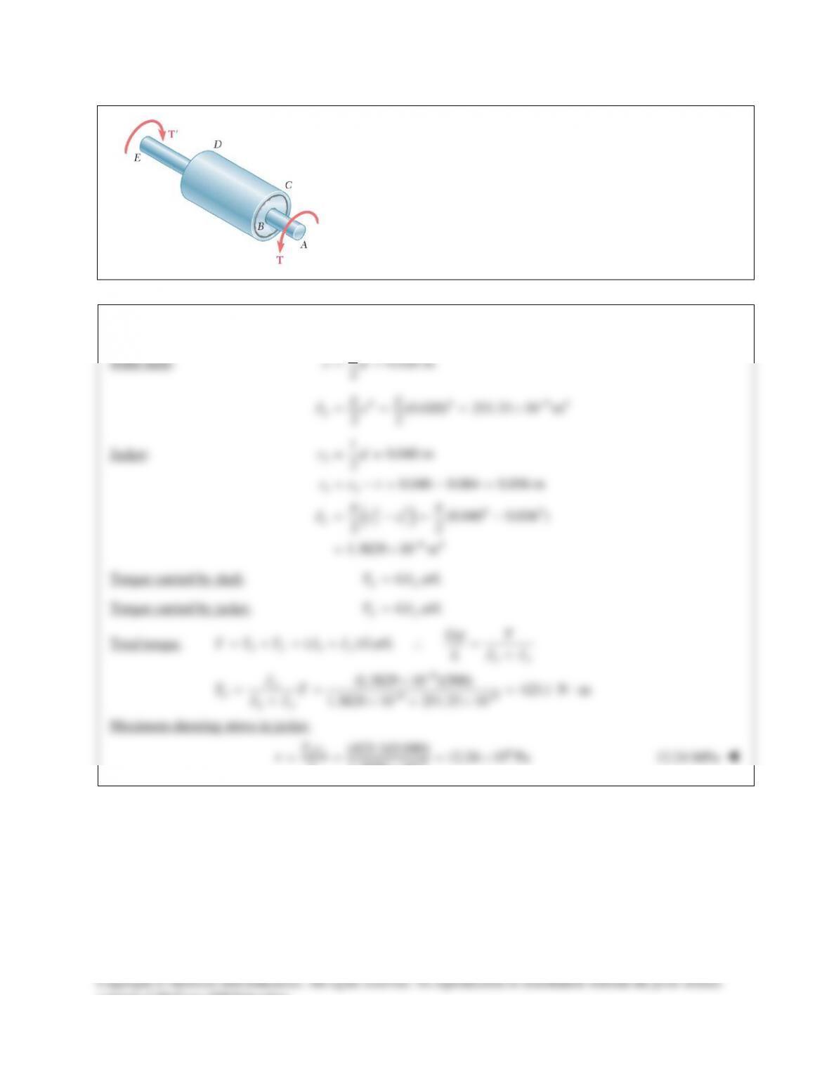
PROBLEM 10.60
The steel jacket CD has been attached to the 40–mm–diameter steel
shaft AE by means of rigid flanges welded to the jacket and to the
rod. The outer diameter of the jacket is 80 mm and its wall thickness
is 4 mm. If 500–N ⋅ m torques are applied as shown, determine the
maximum shearing stress in the jacket.
SOLUTION
Solid shaft:
10.020 m
2
cd= =
4 4 94
(0.020) 251.33 10 m
22
S
Jc
ππ
−
= = = ×
Jacket:
( )
2
12
44 4 4
21
64
10.040 m
2
0.040 0.004 0.036 m
(0.040 0.036 )
22
1.3829 10 m
J
cd
cct
J cc
ππ
−
= =
= −= − =
= −= −
= ×
Torque carried by shaft.
/
SS
T GJ L
ϕ
=
Torque carried by jacket.
/
JJ
T GJ L
ϕ
=
Total torque.
6
66
( ) /
(1.3829 10 )(500) 423.1 N m
1.3829 10 251.33 10
ϕ
ϕ
−
−−
=+= + ∴ = +
×
= = = ⋅
+×+ ×
SJ SJ SJ
J
JSJ
GT
T T T J JGL LJJ
J
TT
JJ
Maximum shearing stress in jacket.
6
26
(423.1)(0.040) 12.24 10 Pa
1.3829 10
J
J
Tc
J
−
= = = ×
×
τ
12.24 MPa
SOLUTION Continued
PROBLEM 10.58
Two solid steel shafts are fitted with flanges that are then
connected by bolts as shown. The bolts are slightly
undersized and permit a 1.5° rotation of one flange with
respect to the other before the flanges begin to rotate as a
single unit. Knowing that G = 77.2 GPa, determine the
maximum shearing stress in each shaft when a torque of T
of magnitude 500 N ⋅ m is applied to the flange indicated.
The torque T is applied to flange B.
SOLUTION
Shaft AB:
4 4 94
99
3
1
, 0.6 m, 0.015 m
2
(0.015) 79.522 10 m
22
(77.2 10 )(79.522 10 )
0.6
10.2318 10
ππ
ϕ
ϕϕ
ϕ
−
−
= = = =
= = = ×
=
××
= =
= ×
AB
AB
AB AB
BAB AB
AB AB
AB B B
B
TT L c d
Jc
TL
GJ
GJ
TL
Shaft CD:
44
94
99 3
1
, 0.9 m, 0.018 m, (0.018)
2 22
164.896 10 m
77.2 10 )(164.896 10 ) 14.1444 10
0.9
ππ
ϕ ϕϕ
−
−
= = = = = =
= ×
(× ×
= = = ×
CD CD CD
CD
CD CD
CD C C C
CD
TT L c d J c
J
GJ
TL
Clearance rotation for flange B:
3
1.5 26.178 10 rad
B
ϕ
−
′= °= ×
Torque to remove clearance:
33
(10.2318 10 )(26.178 10 ) 267.85 N m
AB
T
−−
′= × ×= ⋅
Torque
T′′
to cause additional rotation
: 500 267.85 232.15 N mT
ϕ
′′ ′′ =−= ⋅
AB CD
TT T
′′ ′′ ′′
= +
33 3
232.15 (10.2318 10 14.1444 10 ) 9.5236 10 rad
ϕϕ
−
′′ ′′
= ×+ × ∴ = ×
33
33
(10.2318 10 )(9.5236 10 ) 97.444 N m
AB
T
−
−
′′ = × ×= ⋅
SOLUTION Continued
PROBLEM 10.59
Two solid steel shafts are fitted with flanges that are then
connected by bolts as shown. The bolts are slightly
undersized and permit a 1.5° rotation of one flange with
respect to the other before the flanges begin to rotate as a
single unit. Knowing that G = 77.2 GPa, determine the
maximum shearing stress in each shaft when a torque of T
of magnitude 500 N ⋅ m is applied to the flange indicated.
The torque T is applied to flange C.
SOLUTION
Shaft AB:
4 4 94
99
3
1
, 0.6 m, 0.015 m
2
(0.015) 79.522 10 m
22
(77.2 10 )(79.522 10 )
0.6
10.2318 10
ππ
ϕ
ϕϕ
ϕ
−
−
= = = =
= = = ×
=
××
= =
= ×
AB AB
AB
AB AB
BAB AB
AB AB
AB B B
AB
B
TT L c d
Jc
TL
GJ
GJ
TL
Shaft CD:
44
94
99 3
1
, 0.9 m, 0.018 m (0.018)
2 22
164.896 10 m
77.2 10 )(164.896 10 ) 14.1444 10
0.9
CD CD CD
CD
CD CD
CD C C C
CD
TT L c d J c
J
GJ
TL
ππ
ϕ ϕϕ
−
−
= = = = = =
= ×
(× ×
= = = ×
Clearance rotation for flange C:
3
1.5 26.178 10 rad
C
ϕ
−
′= °= ×
Torque to remove clearance:
33
(14.1444 10 )(26.178 10 ) 370.27 N m
CD
T
−
′= × ×= ⋅
Torque
T′′
to cause additional rotation
: 500 370.27 129.730 N mT
ϕ
′′ ′′ =−= ⋅
AB CD
TT T
′′ ′′ ′′
= +
33 3
129.730 (10.2318 10 14.1444 10 ) 5.3220 10 rad
ϕϕ
−
′′ ′′
= ×+ × = ×
33
(10.2318 10 )(5.3220 10 ) 54.454 N m
AB
T
−
′′ = × ×= ⋅
SOLUTION Continued
consent of McGraw–Hill Education.
PROBLEM 10.60
The steel jacket CD has been attached to the 40–mm–diameter steel
shaft AE by means of rigid flanges welded to the jacket and to the
rod. The outer diameter of the jacket is 80 mm and its wall thickness
is 4 mm. If 500–N ⋅ m torques are applied as shown, determine the
maximum shearing stress in the jacket.
SOLUTION
Solid shaft:
10.020 m
2
cd= =
4 4 94
(0.020) 251.33 10 m
22
S
Jc
ππ
−
= = = ×
Jacket:
( )
2
12
44 4 4
21
64
10.040 m
2
0.040 0.004 0.036 m
(0.040 0.036 )
22
1.3829 10 m
J
cd
cct
J cc
ππ
−
= =
= −= − =
= −= −
= ×
Torque carried by shaft.
/
SS
T GJ L
ϕ
=
Torque carried by jacket.
/
JJ
T GJ L
ϕ
=
Total torque.
6
66
( ) /
(1.3829 10 )(500) 423.1 N m
1.3829 10 251.33 10
ϕ
ϕ
−
−−
=+= + ∴ = +
×
= = = ⋅
+×+ ×
SJ SJ SJ
J
JSJ
GT
T T T J JGL LJJ
J
TT
JJ
Maximum shearing stress in jacket.
6
26
(423.1)(0.040) 12.24 10 Pa
1.3829 10
J
J
Tc
J
−
= = = ×
×
τ
12.24 MPa