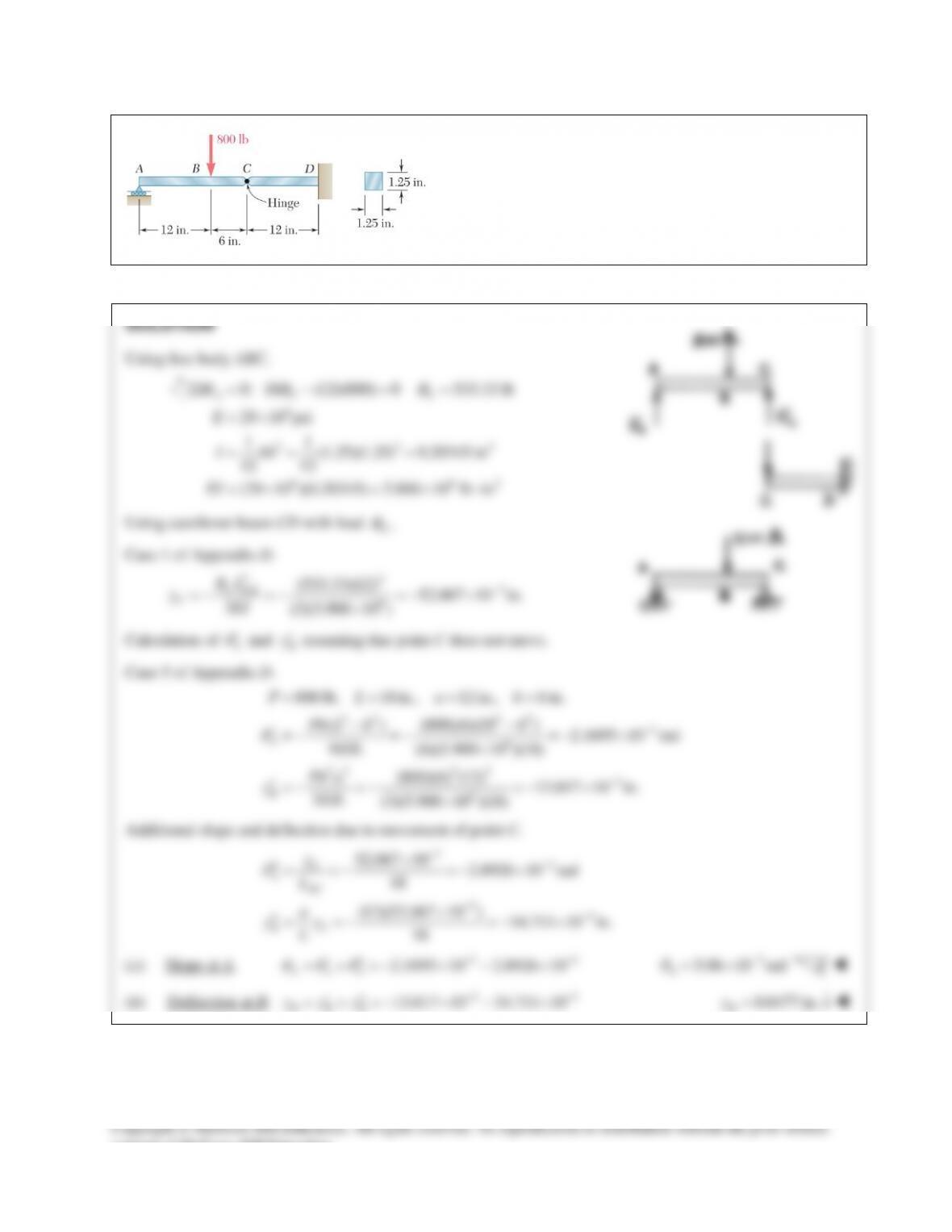
PROBLEM 15.45
The two beams shown have the same cross section and are
joined by a hinge at C. For the loading shown, determine
(a) the slope at point A, (b) the deflection at point B. Use
6
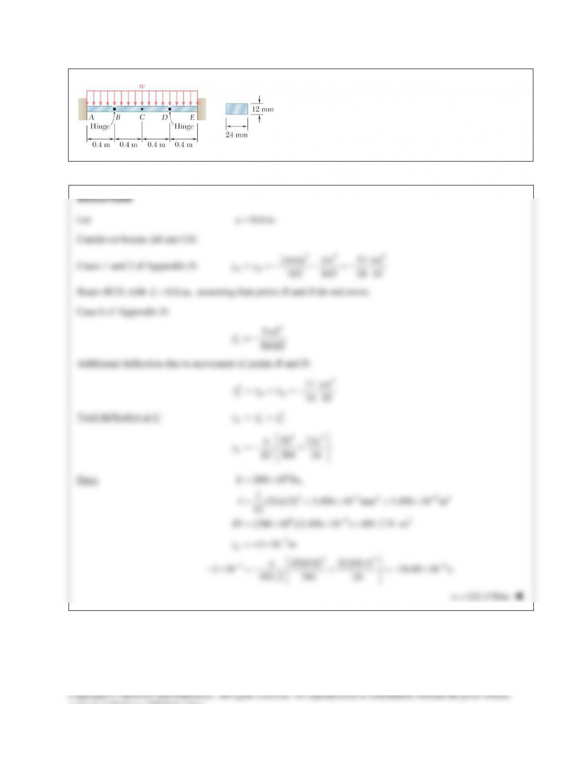
PROBLEM 15.46
A central beam BD is joined at hinges to two cantilever
beams AB and DE. All beams have the cross section shown.
For the loading shown, determine the largest w so that the
deflection at C does not exceed 3 mm. Use
200 GPa.E=
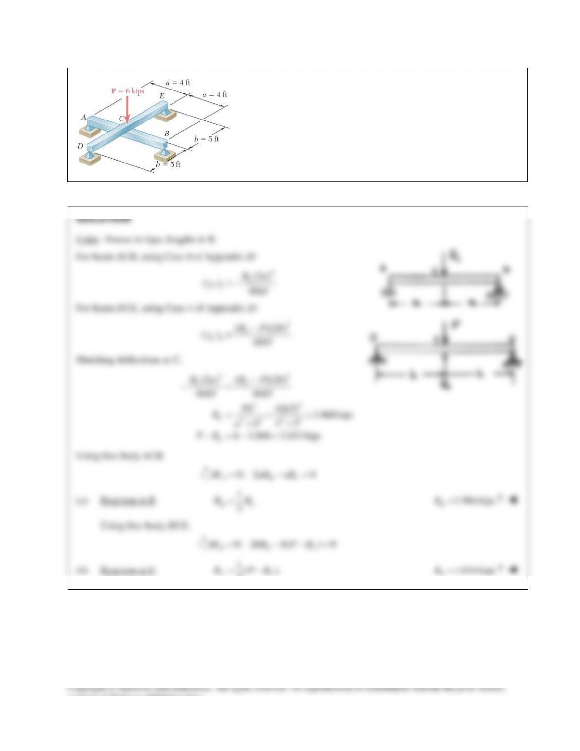
PROBLEM 15.47
For the loading shown, and knowing that beams AB and DE have
the same flexural rigidity, determine the reaction (a) at B, (b) at E.
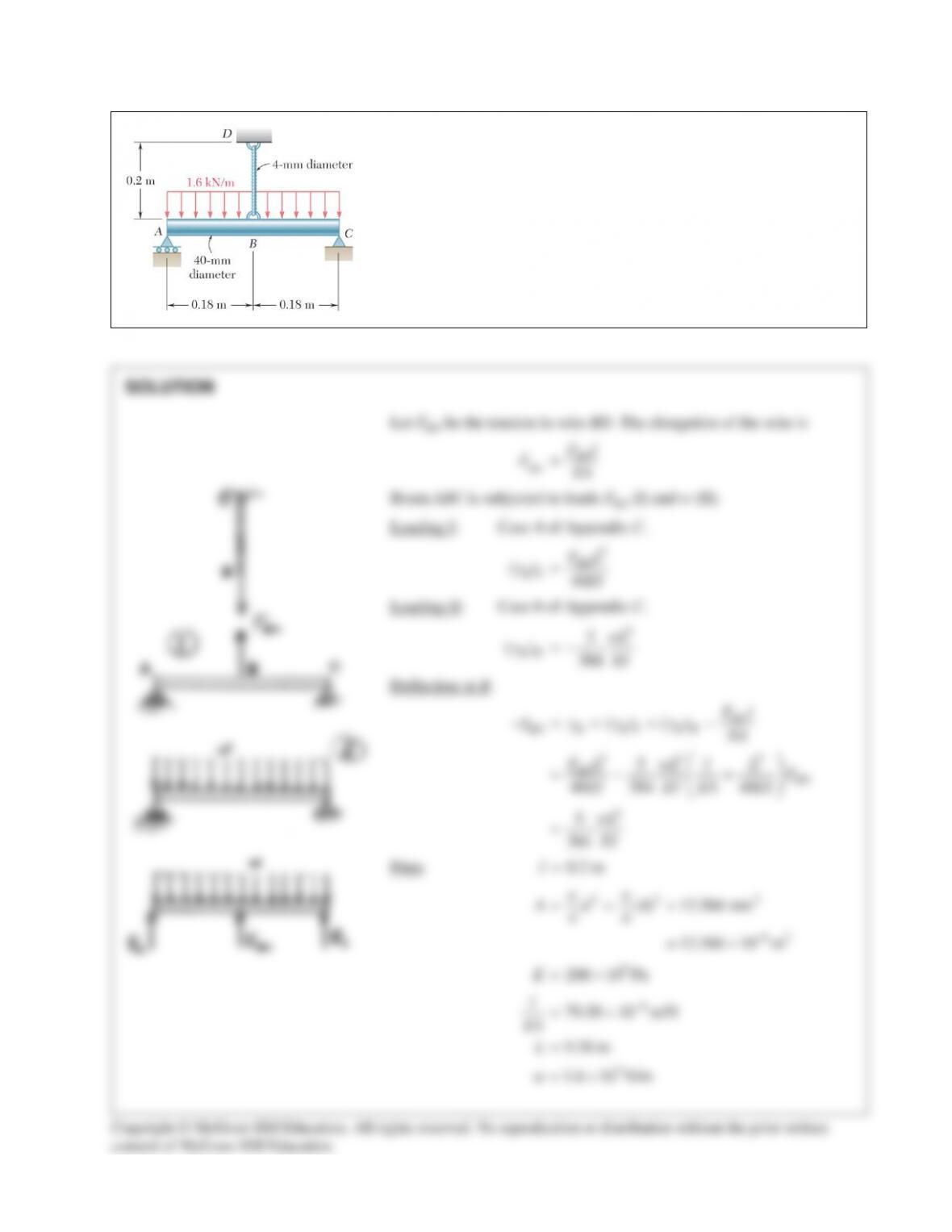
PROBLEM 15.48
Knowing that the rod ABC and the wire BD are both made of steel,
determine (a) the deflection at B, (b) the reaction at A. Use E = 200 GPa.
PROBLEM 15.48 (Continued)
4
4 3 4 94
40 125.66 10 mm 125.66 10 m
4 42
ππ
−
== =×=×
IC
9 9 32
(200 10 )(125.66 10 ) 25.132 10 N m
−
=× ×= ×⋅EI
3 34
933
(0.36) (5)(1.6 10 )(0.36)
79.58 10 (48)(25.132 10 ) (384)(25.132 10 )
BD
F
−
×
×+ =
××
96
118.256 10 13.923 10 117.74 N
BD BD
FF
−−
×=× =
(a) Deflection at B.
96
(117.74)(79.58 10 ) 9.37 10 m 0.00937 mm
BD
B
Fl
EA
−−
== ×=× = ↓
δ
(b)
[ ]
11
[ ] (1600)(0.36) 117.74 229 N
22
A C BD
R R wL F== −= − = ↑
consent of McGraw–Hill Education.
PROBLEM 15.49
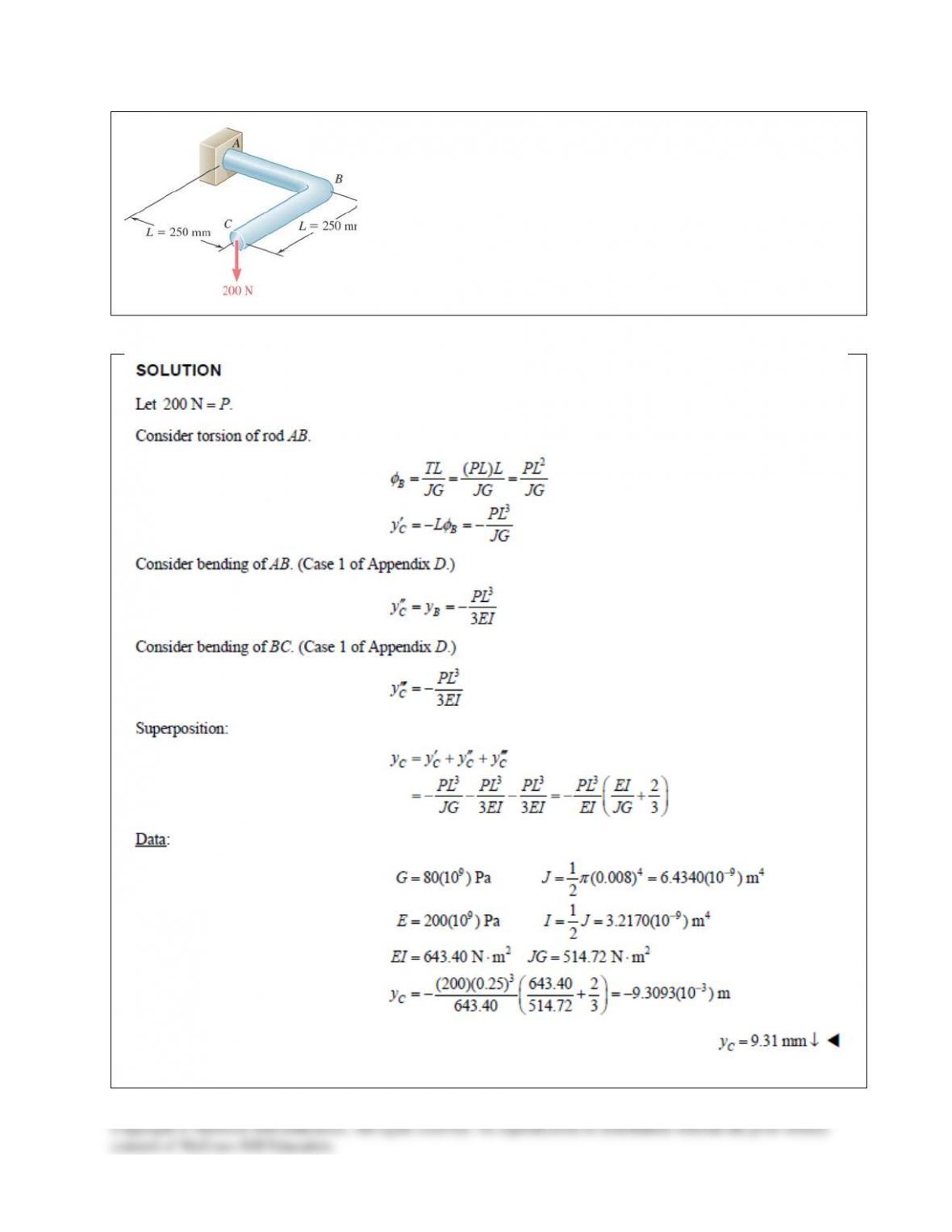
A 16–mm–diameter rod ABC has been bent into the shape shown.
Determine the deflection of end C after the 200–N force is applied. Use
E = 200 GPa and G = 80 GPa.
PROBLEM 15.50
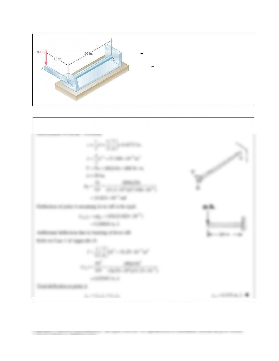
A
7
8
-in.-diameter
rod BC is attached to the lever AB and to
the fixed support at C. Lever AB has a uniform cross
section
3
8
in. thick and 1 in. deep. For the loading shown,
determine the deflection of point A. Use
6
29 10 psiE= ×
and
6
11.2 10 psi.G= ×
SOLUTION
PROBLEM 15.51
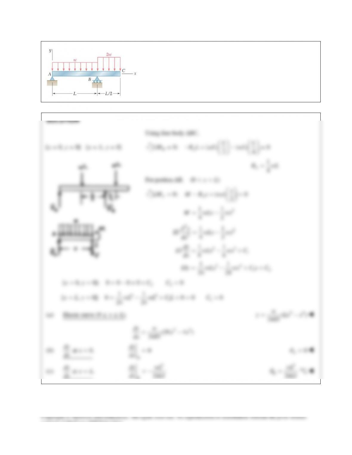
For the beam and loading shown, determine (a) the equation of the
elastic curve for portion AB of the beam, (b) the slope at A, (c) the
slope at B.
PROBLEM 15.52
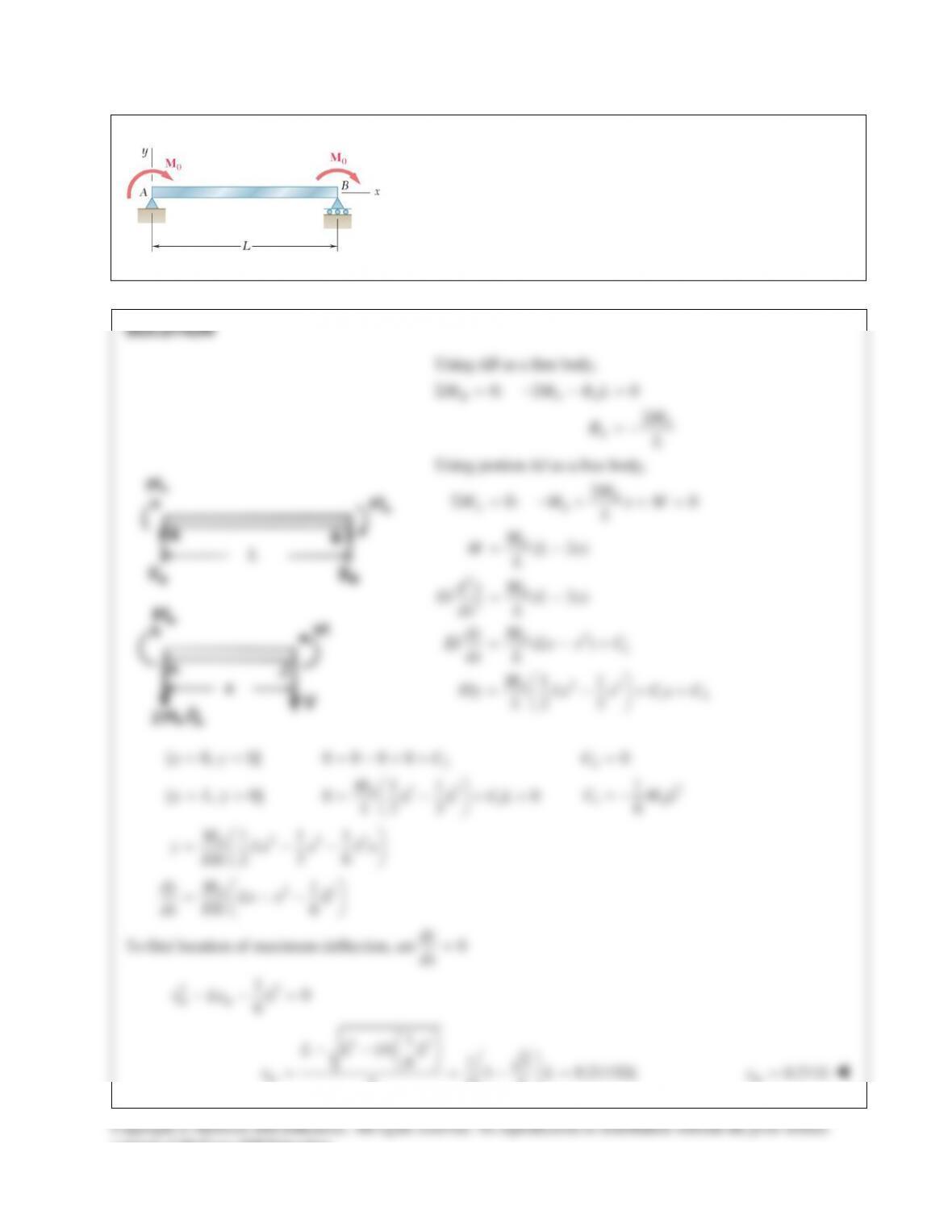
(a) Determine the location and magnitude of the maximum absolute
deflection in AB between A and the center of the beam.
(b) Assuming that beam AB is a W460 × 113, M0 = 224 kN ⋅ m, and
E = 200 GPa, determine the maximum allowable length L of the
beam if the maximum deflection is not to exceed 1.2 mm.
PROBLEM 15.52 (Continued)
( ) ( ) ( )
223
0
2
0
111
0.21132 0.21132 0.21132
236
0.0160375
m
ML
yEI
ML
EI
= −−
= −
2
0
0.0160375=
m
ML
yEI
2
0
0.01604=
m
ML
yEI
Solving for L,
1/2
0
0.0160375
m
EI y
LM
=
Data:
9
64
64
200 10 Pa,
554 10 mm
554 10 m
−
= ×
= ×
= ×
E
I
3
3
0
1.2 mm 1.2 10 m,
224 10 N m
= = ×
=×⋅
m
y
M
1/2
9 63
3
(200 10 )(554 10 )(1.2 10 ) 6.08 m
(0.0160375)(224 10 )
L
−−
×××
= =
×
consent of McGraw–Hill Education.
PROBLEM 15.46
A central beam BD is joined at hinges to two cantilever
beams AB and DE. All beams have the cross section shown.
For the loading shown, determine the largest w so that the
deflection at C does not exceed 3 mm. Use
200 GPa.E=
PROBLEM 15.47
For the loading shown, and knowing that beams AB and DE have
the same flexural rigidity, determine the reaction (a) at B, (b) at E.
PROBLEM 15.48
Knowing that the rod ABC and the wire BD are both made of steel,
determine (a) the deflection at B, (b) the reaction at A. Use E = 200 GPa.
PROBLEM 15.48 (Continued)
4
4 3 4 94
40 125.66 10 mm 125.66 10 m
4 42
ππ
−
== =×=×
IC
9 9 32
(200 10 )(125.66 10 ) 25.132 10 N m
−
=× ×= ×⋅EI
3 34
933
(0.36) (5)(1.6 10 )(0.36)
79.58 10 (48)(25.132 10 ) (384)(25.132 10 )
BD
F
−
×
×+ =
××
96
118.256 10 13.923 10 117.74 N
BD BD
FF
−−
×=× =
(a) Deflection at B.
96
(117.74)(79.58 10 ) 9.37 10 m 0.00937 mm
BD
B
Fl
EA
−−
== ×=× = ↓
δ
(b)
[ ]
11
[ ] (1600)(0.36) 117.74 229 N
22
A C BD
R R wL F== −= − = ↑
consent of McGraw–Hill Education.
PROBLEM 15.49
A 16–mm–diameter rod ABC has been bent into the shape shown.
Determine the deflection of end C after the 200–N force is applied. Use
E = 200 GPa and G = 80 GPa.
PROBLEM 15.50
A
7
8
-in.-diameter
rod BC is attached to the lever AB and to
the fixed support at C. Lever AB has a uniform cross
section
3
8
in. thick and 1 in. deep. For the loading shown,
determine the deflection of point A. Use
6
29 10 psiE= ×
and
6
11.2 10 psi.G= ×
SOLUTION
PROBLEM 15.51
For the beam and loading shown, determine (a) the equation of the
elastic curve for portion AB of the beam, (b) the slope at A, (c) the
slope at B.
PROBLEM 15.52
(a) Determine the location and magnitude of the maximum absolute
deflection in AB between A and the center of the beam.
(b) Assuming that beam AB is a W460 × 113, M0 = 224 kN ⋅ m, and
E = 200 GPa, determine the maximum allowable length L of the
beam if the maximum deflection is not to exceed 1.2 mm.
PROBLEM 15.52 (Continued)
( ) ( ) ( )
223
0
2
0
111
0.21132 0.21132 0.21132
236
0.0160375
m
ML
yEI
ML
EI
= −−
= −
2
0
0.0160375=
m
ML
yEI
2
0
0.01604=
m
ML
yEI
Solving for L,
1/2
0
0.0160375
m
EI y
LM
=
Data:
9
64
64
200 10 Pa,
554 10 mm
554 10 m
−
= ×
= ×
= ×
E
I
3
3
0
1.2 mm 1.2 10 m,
224 10 N m
= = ×
=×⋅
m
y
M
1/2
9 63
3
(200 10 )(554 10 )(1.2 10 ) 6.08 m
(0.0160375)(224 10 )
L
−−
×××
= =
×
consent of McGraw–Hill Education.