PROBLEM 12.19
Draw the shear and bending–moment diagrams for the beam
and loading shown and determine the maximum normal stress
due to bending.
SOLUTION
0:
B
M∑=
(11)(25) 10 (8)(25) (2)(25) 0 52.5 kipsC−+ + = =C
0:
C
M∑=
(1)(25) (2)(25) (8)(25) 10 0 22.5 kipsB− − += =B
Shear:
A to
C−
:
25 kipsV= −
C+ to D−:
27.5 kipsV=
D+ to E−:
2.5 kipsV=
E+ to B:
22.5 kipsV= −
Bending moments:
At C,
0: (1)(25) 0
C
MM∑ = +=
25 kip ftM=−⋅
At D,
0: (3)(25) (2)(52.5) 0
D
MM∑ = − +=
30 kip ftM= ⋅
At E,
0: (2)(22.5) 0 45 kip ft
E
MM M∑ = −+ = = ⋅
max 45 kip ft 540 kip in.M= ⋅= ⋅
For
12 35
S×
rolled steel section,
3
38.1 in
S=
Normal stress:
540 14.17 ksi
38.1
M
S
s
= = =
14.17 ksi
s
=
consent of McGraw–Hill Education.
PROBLEM 12.20
Draw the shear and bending–moment diagrams for the beam
and loading shown and determine the maximum normal stress
due to bending.
SOLUTION
0:
M∑=
consent of McGraw–Hill Education.
0:
0:
PROBLEM 12.20 (Continued)
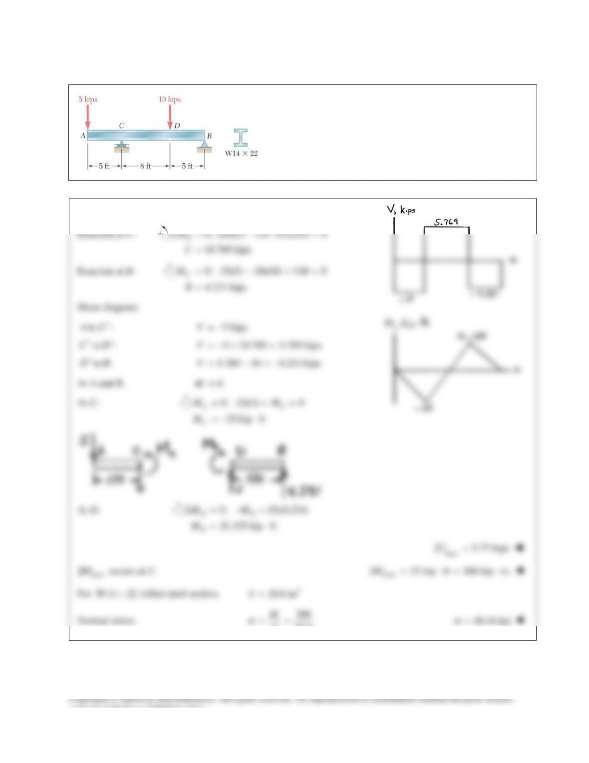
PROBLEM 12.21
Draw the shear and bending–moment diagrams for the beam
and loading shown, and determine the maximum normal stress
due to bending.
SOLUTION
Reaction at C:
0: (18)(5) 13 +(5)(10) 0
10.769 kips
B
MC
C
Σ= − =
=
Reaction at B:
0: (5)(5) (8)(10) 13 0
4.231 kips
C
MB
B
= − +=
=
Shear diagram:
to : 5 kips
to : 5 10.769 5.769 kips
to : 5.769 10 4.231 kips
AC V
CD V
DB V
−
+−
+
= −
=−+ =
= −=−
At A and B,
0M=
At C,
0: (5)(5) 0
25 kip ft
CC
C
MM
M
= +=
=−⋅
At D,
0: (5)(4.231)
21.155 kip ft
DD
D
MM
M
Σ=−+
= ⋅
max
5.77 kipsV=
max
||M
occurs at C.
max
| | 25 kip ft 300 kip in.M= ⋅= ⋅
For
W14 22×
rolled–steel section,
3
29.0 inS=
Normal stress:
300
29.0
M
S
σ
= =
10.34 ksi
σ
=
consent of McGraw–Hill Education.
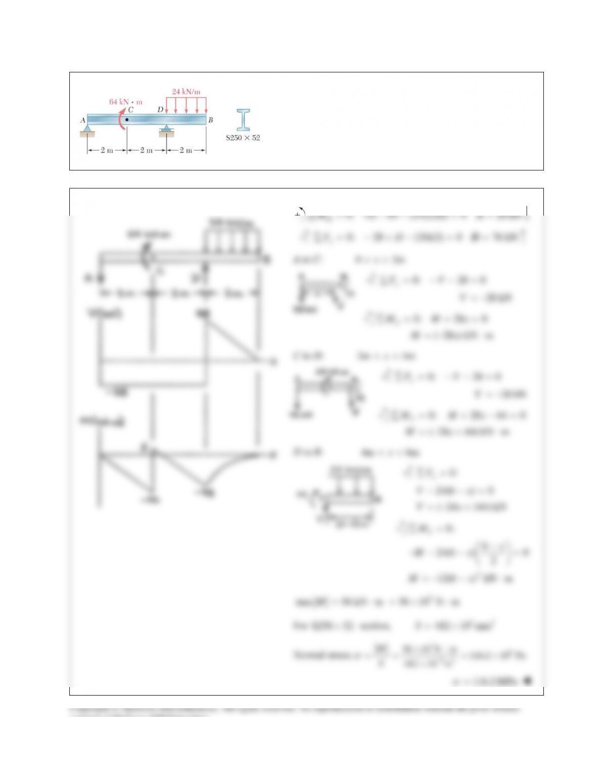
PROBLEM 12.22
Draw the shear and bending–moment diagrams for the beam
and loading shown and determine the maximum normal stress
due to bending.
SOLUTION
Reactions:
0: 4 64 (24)(2)(1) 0 28 kN
D
MA∑ = −− = =A
0: 28 (24)(2) 0 76 kN
y
FD∑ = − +− = =D
A to C:
0 2mx<<
0: 28 0
28 kN
y
FV
V
∑ = −− =
= −
0: 28 0
( 28 ) kN m
J
M Mx
Mx
∑= + =
=−⋅
C to D:
2m 4mx<<
0: 28 0
28 kN
y
FV
V
∑ = −− =
= −
0: 28 64 0
( 28 64) kN m
J
M Mx
Mx
∑ = + −=
=−+ ⋅
D to B:
4m 6mx<<
0:
24(6 ) 0
( 24 144) kN
y
F
Vx
Vx
∑=
− −=
=−+
2
0:
6
24(6 ) 0
2
12(6 ) kN m
J
M
x
Mx
Mx
∑=
−
−− − =
=−− ⋅
3
max 56 kN m 56 10 N mM= ⋅=× ⋅
For
S250 52×
section,
33
482 10 mmS= ×
Normal stress:
36
63
56 10 N m 116.2 10 Pa
482 10 m
M
S
σ
−
×⋅
= = = ×
×
116.2 MPa
σ
=
consent of McGraw–Hill Education.
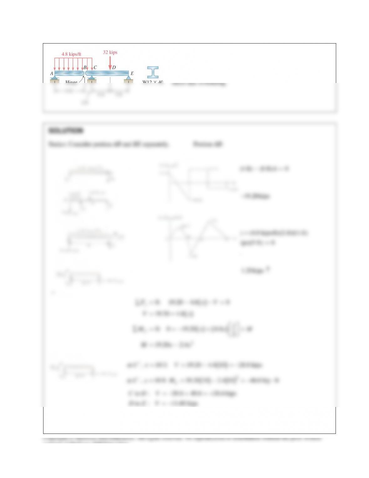
PROBLEM 12.23
Draw the shear and bending–moment diagrams for the beam
and loading shown and determine the maximum normal
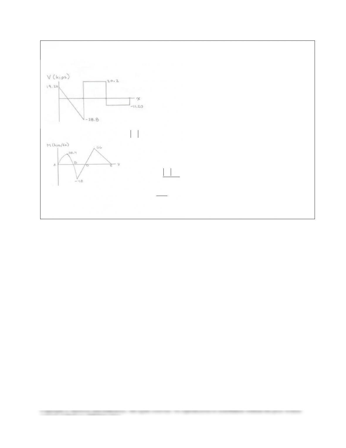
PROBLEM 12.23 (Continued)
Bending Moment at D:
( )
0: 11.20 5 0
56.0 kip ft
DD
D
MM
M
Σ= − + =
= ⋅
From the diagram,
max
56 kip ft 672 kip in.M= ⋅= ⋅
For
W12 40
×
rolled–steel shape,
3
51.5 in
x
S=
Stress:
max
m
M
S
σ
=
672 13.05 ksi
51.5
m
σ
= =
13.05 ksi
m
σ
=
consent of McGraw–Hill Education.
PROBLEM 12.24
Knowing that
3 kipsW=
, draw the shear and bending–moment
diagrams for beam AB and determine the maximum normal stress
due to bending.
SOLUTION
By symmetry,
AB=
0: 2 3 2 0
0.5 kips
y
FA B
AB
Σ = −+−+ =
= =
Shear:
to : 0.5 kipsAC V
−
=
to : 1.5 kipsCD V
+−
= −
to : 1.5 kipsDE V
+− =
to : 0.5 kipsEB V
+
= −
Bending moment:
max
1.50 kips
V=
At C,
0: (3)(0.5) 0
CC
MMΣ= − =
1.5 kip ft
C
M= ⋅
At D,
0: (6)(0.5) (3)(2) 0
DD
MM+Σ = − + =
3 kip ft
D
M=−⋅
By symmetry,
1.5 kip ft at .
ME= ⋅
1.5 kip ft
E
M= ⋅
max| | 3.00 kip ft 36.0 kip in.M= ⋅= ⋅
occurs at E.
For
3
W12 16, 17.1 in
x
S×=
Normal stress:
max
max
| | 36
17.1
x
M
S
σ
= =
max
2.11 ksi
σ
=
consent of McGraw–Hill Education.
PROBLEM 12.25
Knowing that
480 N,PQ
= =
determine (a) the distance a
for which the absolute value of the bending moment in the
beam is as small as possible, (b) the corresponding maximum
normal stress due to bending. (Hint: Draw the bending-
moment diagram and equate the absolute values of the largest
positive and negative bending moments obtained.)
SOLUTION
480 N 480 NPQ= =
Reaction at A:
0: 480( 0.5)
480(1 ) 0
720
960 N
D
M Aa a
a
Aa
Σ = −+ −
− −=
= −
Bending moment at C:
0: 0.5 0
360
0.5 480 N m
CC
C
M AM
MA a
Σ=− + =
==−⋅
Bending moment at D:
0: 480(1 ) 0
480(1 ) N m
DD
D
MM a
Ma
Σ = − − −=
=−−⋅
(a) Equate:
360
480(1 ) 480
DC
MM a a
− = −= −
0.86603 m
a=
866 mm
a=
128.62 N 64.31 N m 64.31 N m
CD
AM M= = ⋅ =−⋅
(b) For rectangular section,
2
1
6
S bh=
2 3 93
1(12)(13) 648 mm 648 10 m
6
S
−
= = = ×
6
max
max 9
| | 64.31 99.2 10 Pa
6.48 10
M
S
σ
−
= = = ×
×
max
99.2 MPa
σ
=
consent of McGraw–Hill Education.
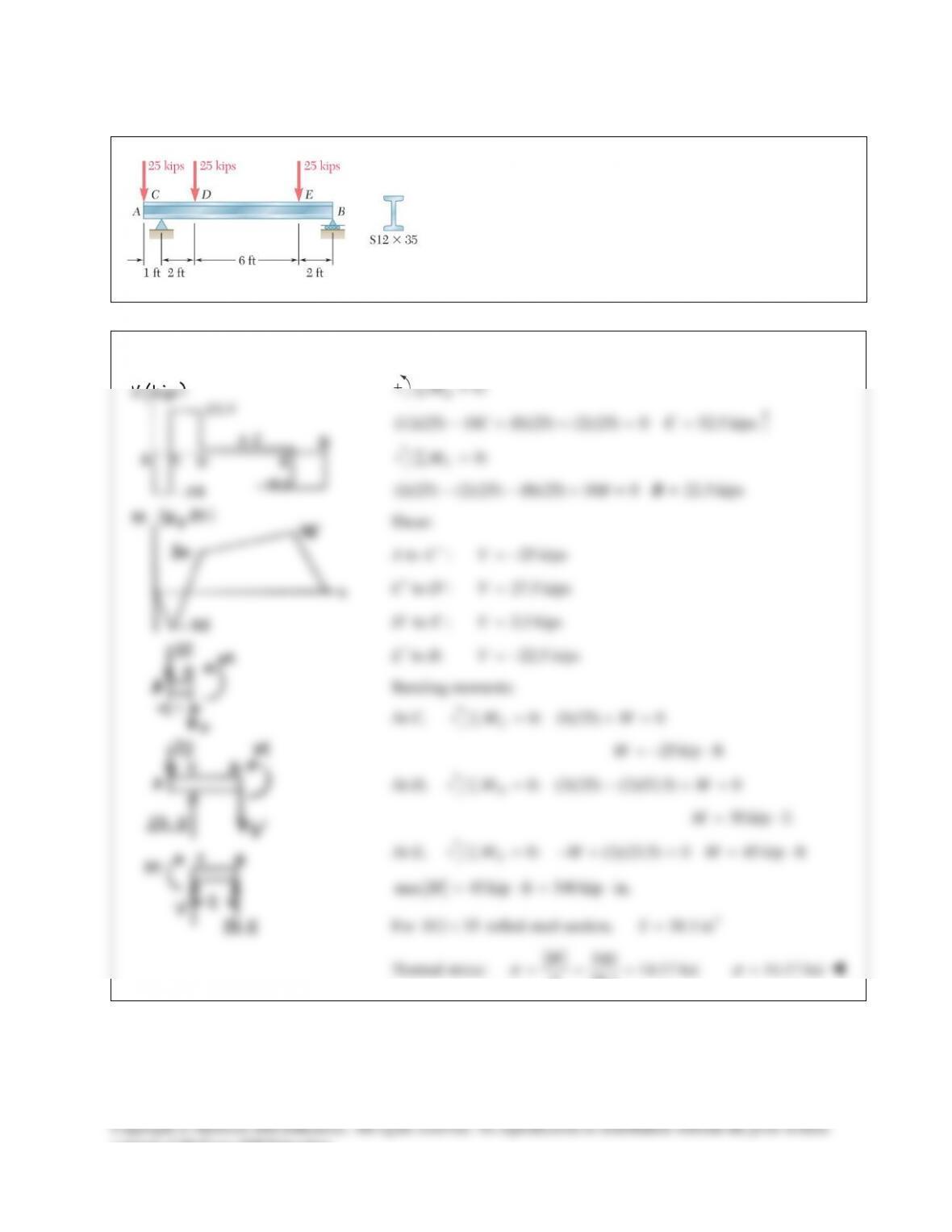
PROBLEM 12.19
Draw the shear and bending–moment diagrams for the beam
and loading shown and determine the maximum normal stress
due to bending.
SOLUTION
0:
B
M∑=
(11)(25) 10 (8)(25) (2)(25) 0 52.5 kipsC−+ + = =C
0:
C
M∑=
(1)(25) (2)(25) (8)(25) 10 0 22.5 kipsB− − += =B
Shear:
A to
C−
:
25 kipsV= −
C+ to D−:
27.5 kipsV=
D+ to E−:
2.5 kipsV=
E+ to B:
22.5 kipsV= −
Bending moments:
At C,
0: (1)(25) 0
C
MM∑ = +=
25 kip ftM=−⋅
At D,
0: (3)(25) (2)(52.5) 0
D
MM∑ = − +=
30 kip ftM= ⋅
At E,
0: (2)(22.5) 0 45 kip ft
E
MM M∑ = −+ = = ⋅
max 45 kip ft 540 kip in.M= ⋅= ⋅
For
12 35
S×
rolled steel section,
3
38.1 in
S=
Normal stress:
540 14.17 ksi
38.1
M
S
s
= = =
14.17 ksi
s
=
consent of McGraw–Hill Education.
PROBLEM 12.20
Draw the shear and bending–moment diagrams for the beam
and loading shown and determine the maximum normal stress
due to bending.
SOLUTION
0:
M∑=
consent of McGraw–Hill Education.
PROBLEM 12.20 (Continued)
PROBLEM 12.21
Draw the shear and bending–moment diagrams for the beam
and loading shown, and determine the maximum normal stress
due to bending.
SOLUTION
Reaction at C:
0: (18)(5) 13 +(5)(10) 0
10.769 kips
B
MC
C
Σ= − =
=
Reaction at B:
0: (5)(5) (8)(10) 13 0
4.231 kips
C
MB
B
= − +=
=
Shear diagram:
to : 5 kips
to : 5 10.769 5.769 kips
to : 5.769 10 4.231 kips
AC V
CD V
DB V
−
+−
+
= −
=−+ =
= −=−
At A and B,
0M=
At C,
0: (5)(5) 0
25 kip ft
CC
C
MM
M
= +=
=−⋅
At D,
0: (5)(4.231)
21.155 kip ft
DD
D
MM
M
Σ=−+
= ⋅
max
5.77 kipsV=
max
||M
occurs at C.
max
| | 25 kip ft 300 kip in.M= ⋅= ⋅
For
W14 22×
rolled–steel section,
3
29.0 inS=
Normal stress:
300
29.0
M
S
σ
= =
10.34 ksi
σ
=
consent of McGraw–Hill Education.
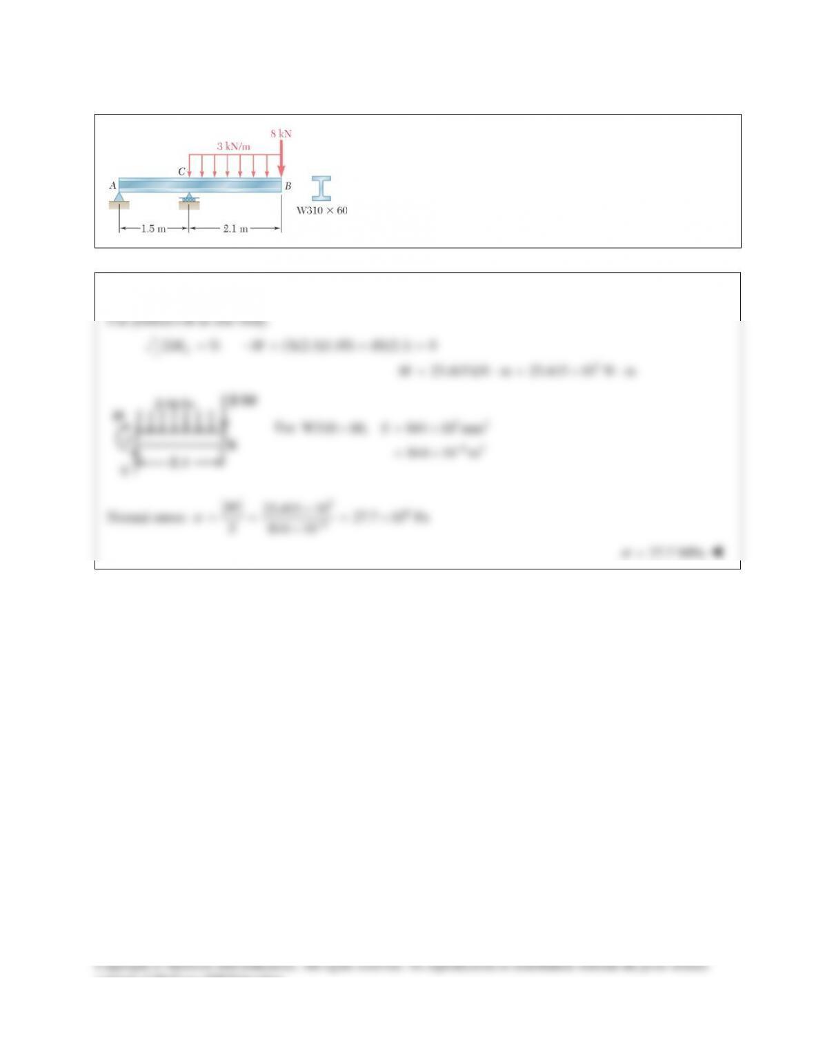
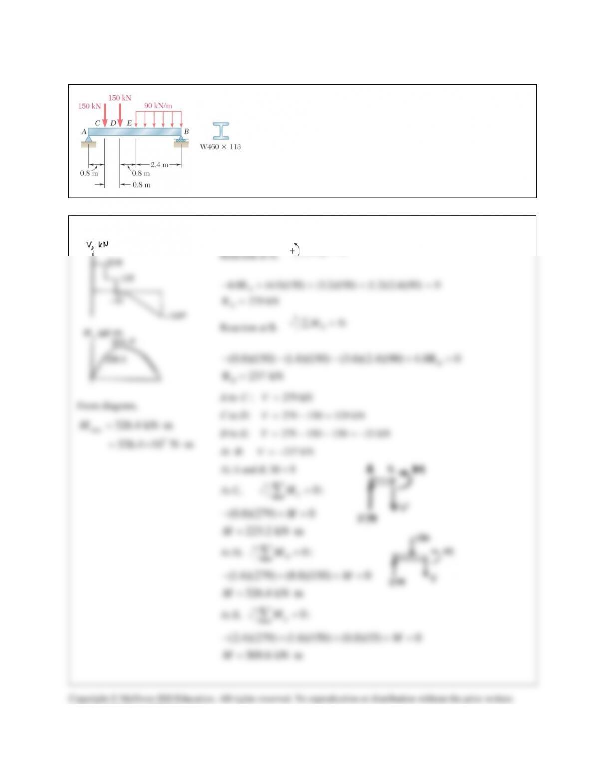
PROBLEM 12.22
Draw the shear and bending–moment diagrams for the beam
and loading shown and determine the maximum normal stress
due to bending.
SOLUTION
Reactions:
0: 4 64 (24)(2)(1) 0 28 kN
D
MA∑ = −− = =A
0: 28 (24)(2) 0 76 kN
y
FD∑ = − +− = =D
A to C:
0 2mx<<
0: 28 0
28 kN
y
FV
V
∑ = −− =
= −
0: 28 0
( 28 ) kN m
J
M Mx
Mx
∑= + =
=−⋅
C to D:
2m 4mx<<
0: 28 0
28 kN
y
FV
V
∑ = −− =
= −
0: 28 64 0
( 28 64) kN m
J
M Mx
Mx
∑ = + −=
=−+ ⋅
D to B:
4m 6mx<<
0:
24(6 ) 0
( 24 144) kN
y
F
Vx
Vx
∑=
− −=
=−+
2
0:
6
24(6 ) 0
2
12(6 ) kN m
J
M
x
Mx
Mx
∑=
−
−− − =
=−− ⋅
3
max 56 kN m 56 10 N mM= ⋅=× ⋅
For
S250 52×
section,
33
482 10 mmS= ×
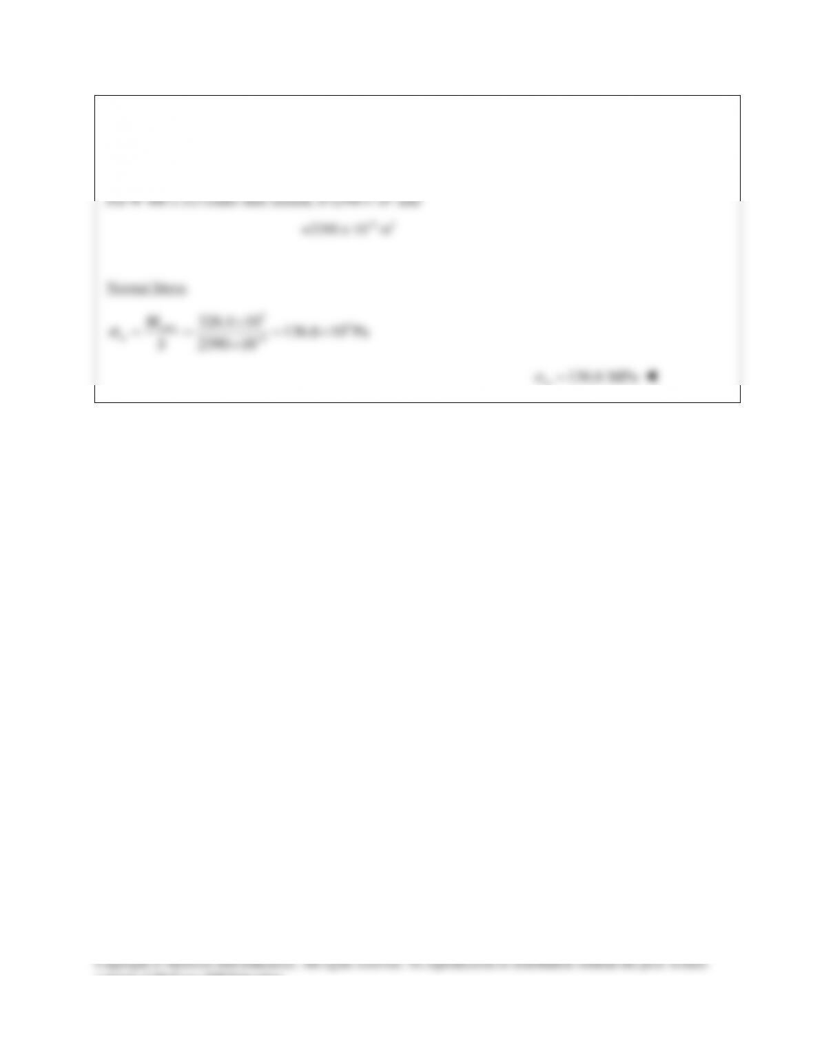
Normal stress:
36
63
56 10 N m 116.2 10 Pa
482 10 m
M
S
σ
−
×⋅
= = = ×
×
116.2 MPa
σ
=
consent of McGraw–Hill Education.
PROBLEM 12.23
Draw the shear and bending–moment diagrams for the beam
and loading shown and determine the maximum normal
PROBLEM 12.23 (Continued)
Bending Moment at D:
( )
0: 11.20 5 0
56.0 kip ft
DD
D
MM
M
Σ= − + =
= ⋅
From the diagram,
max
56 kip ft 672 kip in.M= ⋅= ⋅
For
W12 40
×
rolled–steel shape,
3
51.5 in
x
S=
Stress:
max
m
M
S
σ
=
672 13.05 ksi
51.5
m
σ
= =
13.05 ksi
m
σ
=
consent of McGraw–Hill Education.
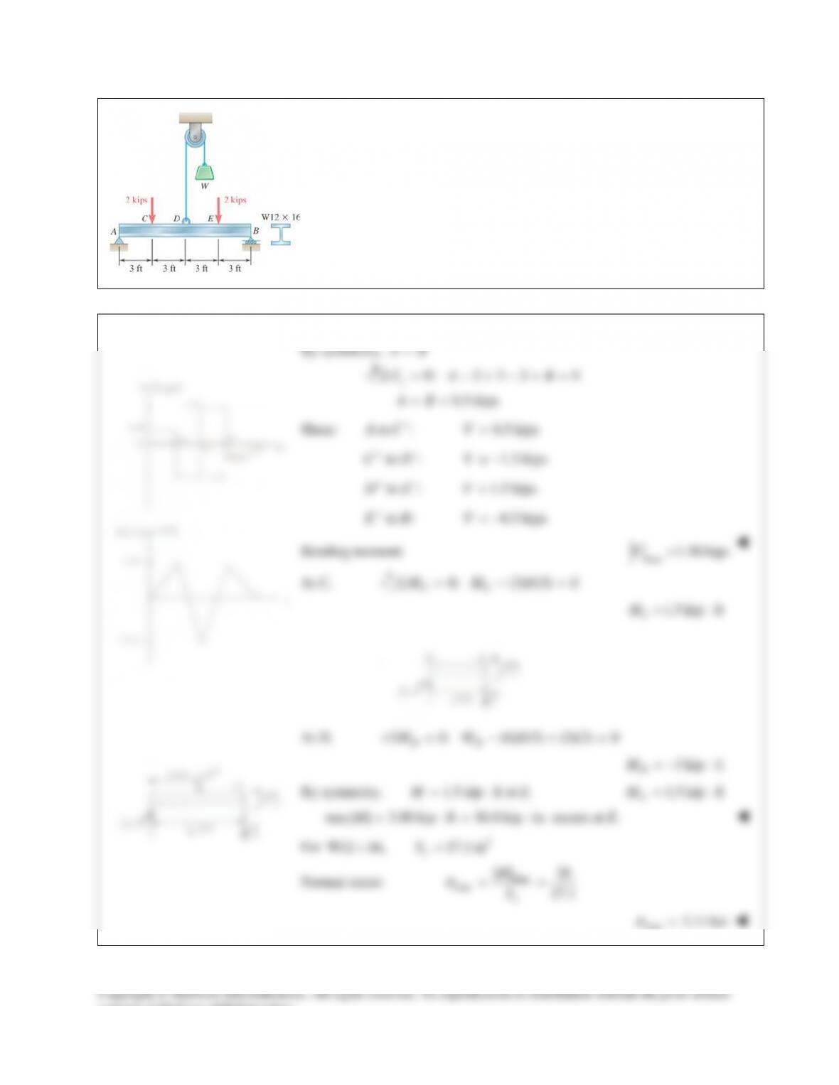
PROBLEM 12.24
Knowing that
3 kipsW=
, draw the shear and bending–moment
diagrams for beam AB and determine the maximum normal stress
due to bending.
SOLUTION
By symmetry,
AB=
0: 2 3 2 0
0.5 kips
y
FA B
AB
Σ = −+−+ =
= =
Shear:
to : 0.5 kipsAC V
−
=
to : 1.5 kipsCD V
+−
= −
to : 1.5 kipsDE V
+− =
to : 0.5 kipsEB V
+
= −
Bending moment:
max
1.50 kips
V=
At C,
0: (3)(0.5) 0
CC
MMΣ= − =
1.5 kip ft
C
M= ⋅
At D,
0: (6)(0.5) (3)(2) 0
DD
MM+Σ = − + =
3 kip ft
D
M=−⋅
By symmetry,
1.5 kip ft at .
ME= ⋅
1.5 kip ft
E
M= ⋅
max| | 3.00 kip ft 36.0 kip in.M= ⋅= ⋅
occurs at E.
For
3
W12 16, 17.1 in
x
S×=
Normal stress:
max
max
| | 36
17.1
x
M
S
σ
= =
max
2.11 ksi
σ
=
consent of McGraw–Hill Education.
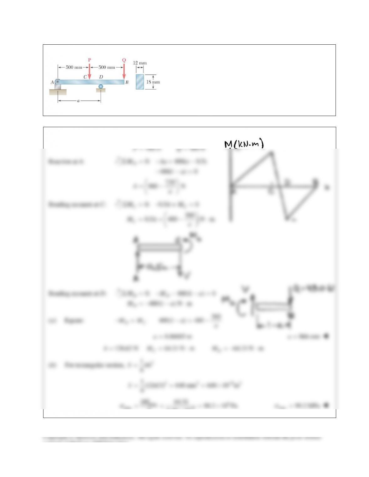
PROBLEM 12.25
Knowing that
480 N,PQ
= =
determine (a) the distance a
for which the absolute value of the bending moment in the
beam is as small as possible, (b) the corresponding maximum
normal stress due to bending. (Hint: Draw the bending-
moment diagram and equate the absolute values of the largest
positive and negative bending moments obtained.)
SOLUTION
480 N 480 NPQ= =
Reaction at A:
0: 480( 0.5)
480(1 ) 0
720
960 N
D
M Aa a
a
Aa
Σ = −+ −
− −=
= −
Bending moment at C:
0: 0.5 0
360
0.5 480 N m
CC
C
M AM
MA a
Σ=− + =
==−⋅
Bending moment at D:
0: 480(1 ) 0
480(1 ) N m
DD
D
MM a
Ma
Σ = − − −=
=−−⋅
(a) Equate:
360
480(1 ) 480
DC
MM a a
− = −= −
0.86603 m
a=
866 mm
a=
128.62 N 64.31 N m 64.31 N m
CD
AM M= = ⋅ =−⋅
(b) For rectangular section,
2
1
6
S bh=
2 3 93
1(12)(13) 648 mm 648 10 m
6
S
−
= = = ×
6
max
max 9
| | 64.31 99.2 10 Pa
6.48 10
M
S
σ
−
= = = ×
×
max
99.2 MPa
σ
=
consent of McGraw–Hill Education.