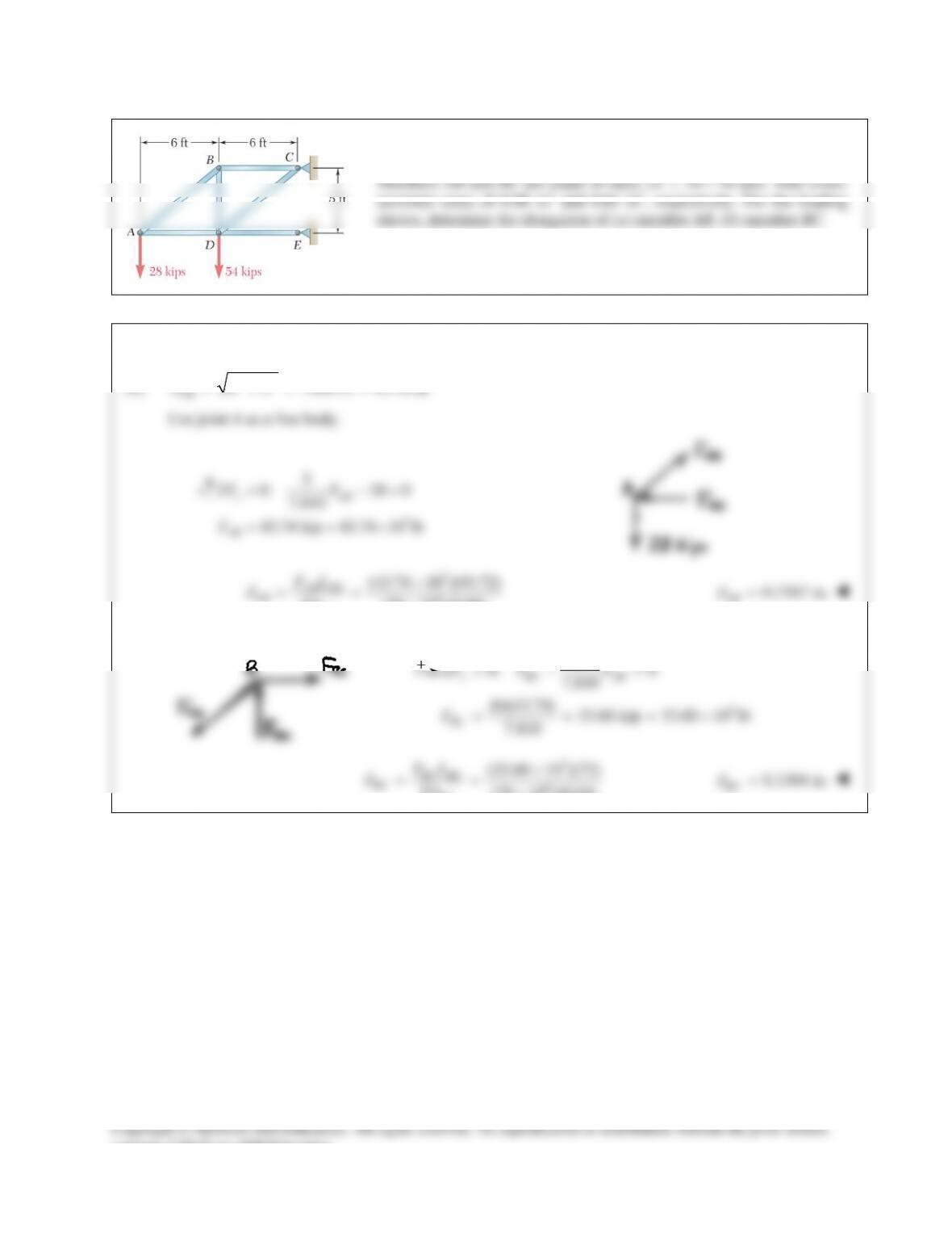
PROBLEM 9.22
Members ABC and DEF are joined with steel links (E = 200 GPa).
Each of the links is made of a pair of 25 × 35–mm plates. Determine
the change in length of (a) member BE, (b) member CF.
SOLUTION
Free body diagram of Member ABC:
0:Σ=
B
M
(0.26 m)(18 kN) (0.18 m) 0
CF
F
−=
26.0 kN
CF
F=
0:Σ=
x
F
18 kN 26.0 kN 0++ =
BE
F
44.0 kN= −
BE
F
Area for link made of two plates:
32
2(0.025 m)(0.035 m) 1.750 10 mA−
= = ×
(a)
3
9 32
6
( 44.0 10 N)(0.240 m)
(200 10 Pa)(1.75 10 m )
30.171 10 m
δ
−
−
−×
= = ××
=−×
BE
BE
FL
EA
0.0302 mm
BE
δ
= −
(b)
3
9 32
6
(26.0 10 N)(0.240 m)
(200 10 Pa)(1.75 10 m )
17.8286 10 m
δ
−
−
×
= = ××
= ×
BF
CF FL
EA
0.01783 mm
CF
δ
=
consent of McGraw–Hill Education.
PROBLEM 9.23
Each of the links AB and CD is made of aluminum
6
( 10.9 10 psi)= ×E
and has a cross–sectional area of 0.2 in2. Knowing that they support the
rigid member BC, determine the deflection of point E.
SOLUTION
Free body BC:
3
0: (32) (22)(1 10 ) 0
687.5 lb
Σ=− + × =
=
C AB
AB
MF
F
3
0: 687.5 1 10 0
312.5 lb
y CD
CD
FF
F
Σ = −× + =
=
3
6
3
6
(687.5)(18) 5.6766 10 in.
(10.9 10 )(0.2)
(312.5)(18) 2.5803 10 in.
(10.9 10 )(0.2)
δδ
δδ
−
−
= = =×=
×
= = =×=
×
AB AB
AB B
CD CD
CD C
FL
EA
FL
EA
Deformation diagram:
3
6
3.0963 10
Slope 32
96.759 10 rad
δδ
θ
−
−
−×
= =
= ×
BC
BC
L
36
3
2.5803 10 (22)(96.759 10 )
4.7090 10 in.
δδ θ
−−
−
= +
= ×+ ×
= ×
E C EC
L
3
4.71 10 in.
E
δ
−
=×↓
consent of McGraw–Hill Education.
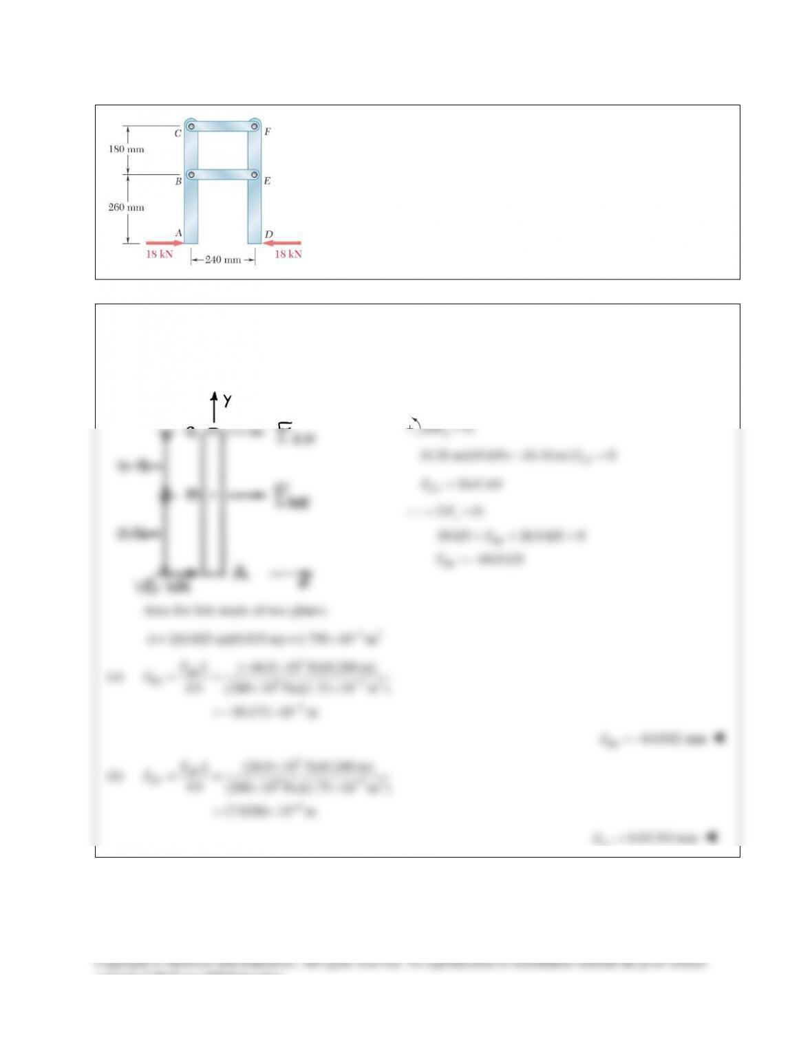
PROBLEM 9.24
Link BD is made of brass
( 105 GPa)E=
and has a cross–sectional area of
240 mm2. Link CE is made of aluminum
( 72 GPa)E=
and has a cross–
sectional area of 300 mm2. Knowing that they support rigid member ABC,
determine the maximum force P that can be applied vertically at point A if
the deflection of A is not to exceed 0.35 mm.
SOLUTION
Free body member AC:
0: 0.350 0.225 0
1.55556
Σ= − =
=
C BD
BD
M PF
FP
0: 0.125 0.225 0
0.55556
Σ= − =
=
B CE
CE
M PF
FP
9
96
9
96
(1.55556 )(0.225) 13.8889 10
(105 10 )(240 10 )
(0.55556 )(0.150) 3.8581 10
(72 10 )(300 10 )
BD BD
B BD BD BD
CE CE
C CE CE CE
FL PP
EA
FL PP
EA
δδ
δδ
−
−
−
−
= = = = ×
××
= = = = ×
××
Deformation Diagram:
From the deformation diagram,
Slope:
99
17.7470 10 78.876 10
0.225
δδ
θ
−−
+×
= = = ×
BC
BC
PP
L
99
9
13.8889 10 (0.125)(78.876 10 )
23.748 10
δδ θ
−−
−
= +
= ×+ ×
= ×
A B AB
L
PP
P
Apply displacement limit.
39
0.35 10 m 23.748 10
δ
−−
=×=×
A
P
3
14.7381 10 N
P= ×
14.74 kNP=
consent of McGraw–Hill Education.
PROBLEM 9.25
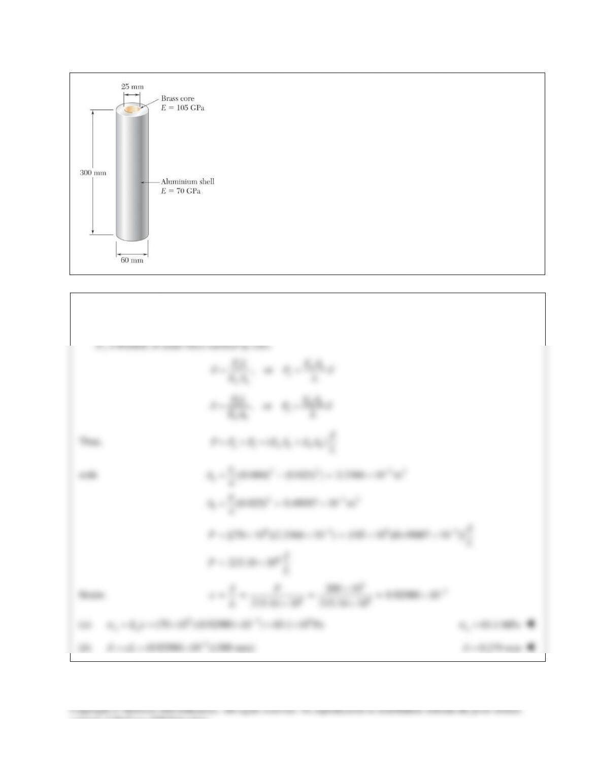
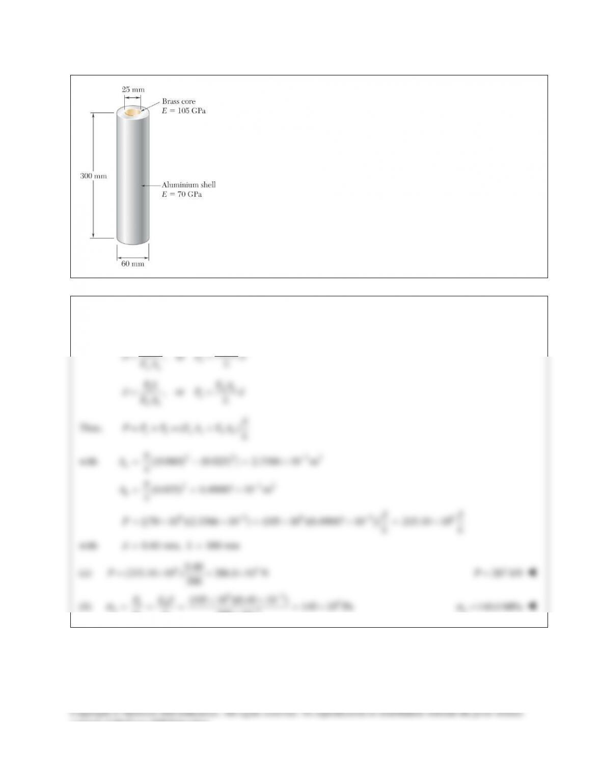
An axial force of 200 kN is applied to the assembly shown by means of
rigid end plates. Determine (a) the normal stress in the aluminum shell,
(b) the corresponding deformation of the assembly.
SOLUTION
Let Pa = Portion of axial force carried by shell.
PROBLEM 9.26
The length of the assembly shown decreases by 0.40 mm when an axial
force is applied by means of rigid end plates. Determine (a) the magnitude
of the applied force, (b) the corresponding stress in the brass core.
SOLUTION
Let Pa = Portion of axial force carried by shell and Pb = Portion of axial force carried by core.
, or
a aa
a
aa
PL E A
P
EA L
δδ
= =
, or
b bb
b
bb
PL E A
P
EA L
δδ
= =
Thus,
()
a b aa bb
P P P EA EA L
δ
=+= +
with
2 2 32
2 32
[(0.060) (0.025) ] 2.3366 10 m
4
(0.025) 0.49087 10 m
4
a
b
A
A
π
π
−
−
= −=×
= = ×
9 39 3 6
[(70 10 )(2.3366 10 ) (105 10 )(0.49087 10 )] 215.10 10
δδ
−−
=× × +× × = ×PLL
with
0.40 mm, 300 mmL
δ
= =
(a)
63
0.40
(215.10 10 ) 286.8 10 N
300
P=×=×
287 kNP=
(b)
93 6
3
(105 10 )(0.40 10 ) 140 10 Pa
300 10
δ
σ
−
−
××
= = = = ×
×
bb
bb
PE
AL
140.0 MPa=
b
σ
consent of McGraw–Hill Education.
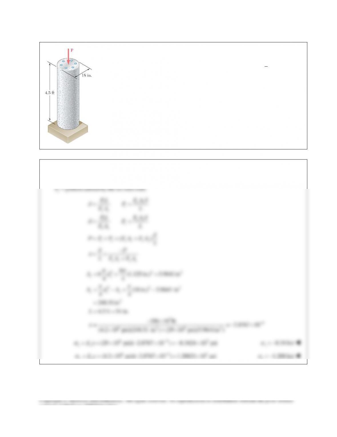
PROBLEM 9.27
The 4.5–ft concrete post is reinforced with six steel bars, each with a
1
8
1
–in. diameter.
Knowing that Es = 29 × 106 psi and Ec = 4.2 × 10⁶ psi, determine the normal stresses
in the steel and in the concrete when a 350–kip axial centric force P is applied to the
post.
SOLUTION
Let
portion of axial force carried by concrete.
portion carried by the six steel rods.
=
=
c
s
P
P
()
c cc
c
cc
s ss
s
ss
c s cc ss
cc ss
PL E A
P
EA L
PL E A
P
EA L
P P P EA EA L
P
L EA EA
δ
δ
δ
δ
δ
δ
ε
= =
= =
=+= +
−
= = +
2 22
2 22
2
34
6 26 2
6
6 (1.125 in.) 5.9641in
44
(18 in.) 5.9641 in
44
248.51in
4.5 ft 54 in.
350 10 lb 2.8767 10
(4.2 10 psi)(248.51 in ) (29 10 psi)(5.9641in )
−
= = =
= −= −
=
= =
−×
= =−×
× +×
ss
c cs
Ad
A dA
L
pp
pp
ε
64
(29 10 psi)( 2.8767 10 ) 8.3424 10 psi
ss
E
sε
−3
==× − ×=− ×
s
s
= −8.34 ksi
6 43
(4.2 10 psi)( 2.8767 10 ) 1.20821 10 psi
−
==× − ×= ×
cc
E
sε
c
s
= −1.208 ksi
consent of McGraw–Hill Education.
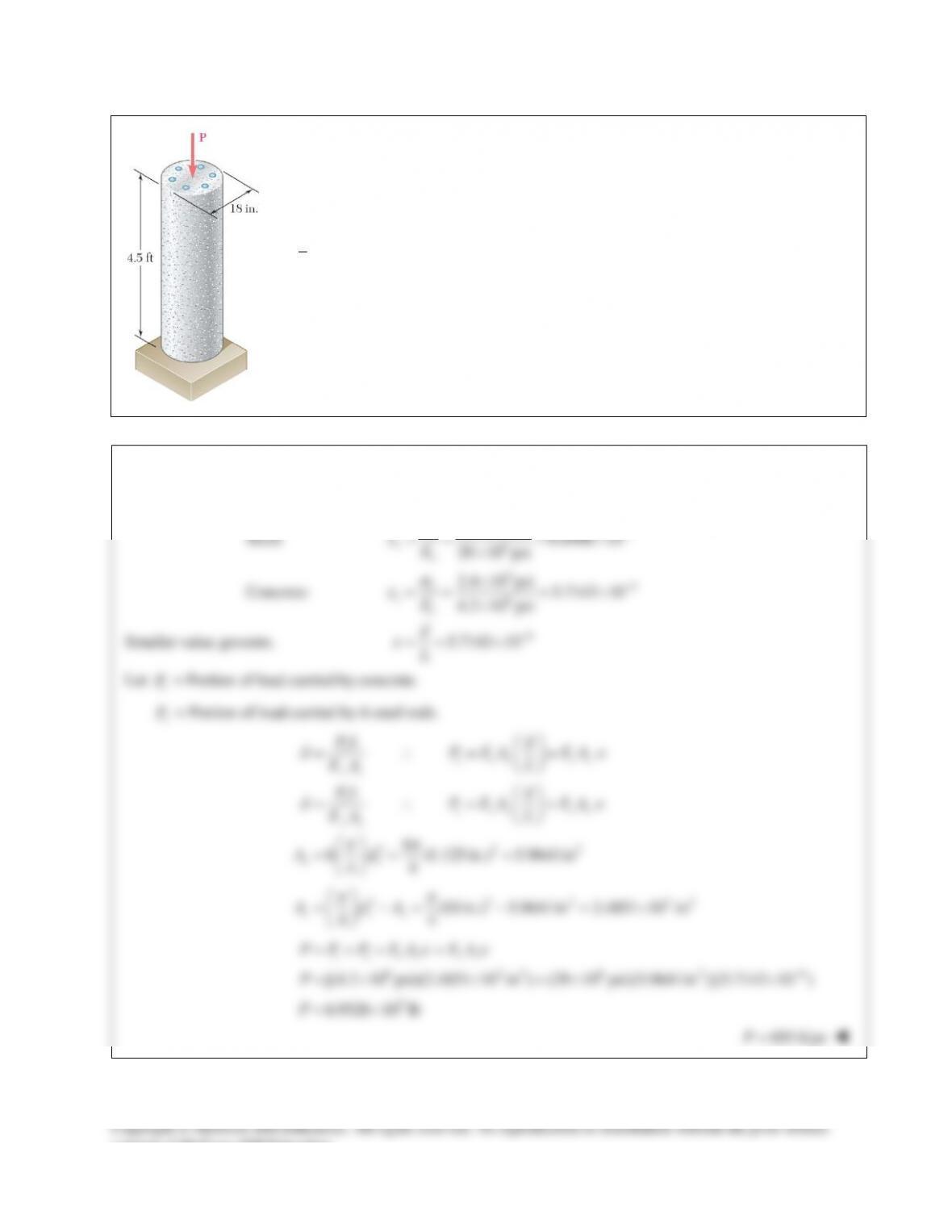
PROBLEM 9.28
For the post of Prob. 9.27, determine the maximum centric force that can be applied if the
allowable normal stress is 20 ksi in the steel and 2.4 ksi in the concrete.
PROBLEM 9.27 The 4.5–ft concrete post is reinforced with six steel bars, each with
a
1
8
1
–in. diameter. Knowing that Es = 29 × 106 psi and Ec = 4.2 × 10⁶ psi, determine
the normal stresses in the steel and in the concrete when a 350–kip axial centric force P
is applied to the post.
SOLUTION
Allowable strain in each material:
Steel:
34
6
20 10 psi 6.8966 10
29 10 psi
s
ε
−
×
= = = ×
×
s
ss
E
Concrete:
34
6
2.4 10 psi 5.7143 10
4.2 10 psi
s
ε
−
×
= = = ×
×
c
cc
E
Smaller value governs.
4
5.7143 10
δ
ε
−
= = ×
L
Let
c
P
= Portion of load carried by concrete.
s
P
= Portion of load carried by 6 steel rods.
δ
δ∈
= ∴= =
cc cc cc
cc
PL P EA EA
EA L
δ
δ∈
= ∴= =
ss ss ss
ss
PL P EA EA
EA L
2 22
6
6 (1.125 in.) 5.9641in
44
ππ
= = =
ss
Ad
2 2 2 22
(18 in.) 5.9641in 2.4851 10 in
44
c cs
A dA
ππ
= −= − = ×
∈∈
=+= +
c s cc ss
P P P EA EA
6 22 6 2 4
[(4.2 10 psi)(2.4851 10 in ) (29 10 psi)(5.9641in )](5.7143 10 )
−
= × × +× ×P
5
6.9526 10 lb= ×P
695 kipsP=
consent of McGraw–Hill Education.
PROBLEM 9.29
Three steel rods (E = 29 × 106 psi) support an 8.5–kip load P. Each of the
rods AB and CD has a 0.32–in2 cross–sectional area and rod EF has a 1–in2
cross–sectional area. Neglecting the deformation of bar BED, determine
(a) the change in length of rod EF, (b) the stress in each rod.
SOLUTION
Use member BED as a free body.
By symmetry, or by
0:∑=
E
M
CD AB
PP=
0: 0
y AB CD EF
F PPPP∑ = + + −=
2AB EF
PP P= +
= = =
CD CD
AB AB EF EF
AB CD EF
AB CD EF
PL
PL PL
EA EA EA
δδδ
Since
and ,
AB CD AB CD AB CD
LL AA
δδ
= = =
B AB D CD E EF
Since member BED is rigid,
EBC
δδδ
= =
0.32 16 0.256
1 20
= ∴=⋅ =⋅=
AB AB EF EF AB EF
AB EF EF EF
AB EF EF AB
PL PL A L
P P PP
EA EA A L
2 2(0.256 ) 1.512
8.5 5.6217 kips
1.512 1.512
0.256(5.6217) 1.43916 kips
= += +=
===
= = =
AB EF EF EF EF
EF
AB CD
PP P P P P
P
P
PP
(a)
3
(5.6217)(16) 0.0031016 in.
(29 10 )(1)
δ
= = =
×
EF EF
EF EF
PL
EA
0.00310 in.
EF
δ
=
(b)
1.43916 4.4974 ksi
0.32
AB
AB CD AB
P
A
ss
= = = =
4.50 ksi
AB CD
ss
= =
5.6217 5.6217 ksi
1
EF
EF EF
P
A
s
= = =
5.62 ksi
EF
s
=
consent of McGraw–Hill Education.
PROBLEM 9.30
Two cylindrical rods, one of steel and the other of brass, are joined at
C and restrained by rigid supports at A and E. For the loading shown
and knowing that
200 GPa
s
E=
and
105 GPa,
b
E=
determine
(a) the reactions at A and E, (b) the deflection of point C.
SOLUTION
A to C:
9
2 3 2 32
6
200 10 Pa
(40) 1.25664 10 mm 1.25664 10 m
4
251.327 10 N
E
A
EA
π
−
= ×
==×=×
= ×
C to E:
9
2 2 62
6
105 10 Pa
(30) 706.86 mm 706.86 10 m
4
74.220 10 N
E
A
EA
π
−
= ×
= = = ×
= ×
A to B:
6
12
180 mm 0.180 m
(0.180)
251.327 10
716.20 10
δ
−
=
= =
= = ×
= ×
A
A
AB
A
PR
L
R
PL
EA
R
B to C:
3
3
6
12 6
60 10
120 mm 0.120 m
( 60 10 )(0.120)
251.327 10
447.47 10 26.848 10
δ
−−
= −×
= =
−×
= = ×
=× −×
A
A
BC
A
PR
L
R
PL
EA
R
consent of McGraw–Hill Education.
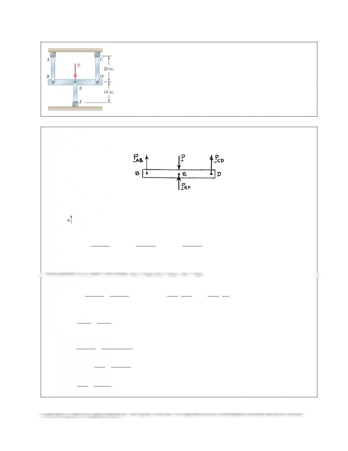
PROBLEM 9.22
Members ABC and DEF are joined with steel links (E = 200 GPa).
Each of the links is made of a pair of 25 × 35–mm plates. Determine
the change in length of (a) member BE, (b) member CF.
SOLUTION
Free body diagram of Member ABC:
0:Σ=
B
M
(0.26 m)(18 kN) (0.18 m) 0
CF
F
−=
26.0 kN
CF
F=
0:Σ=
x
F
18 kN 26.0 kN 0++ =
BE
F
44.0 kN= −
BE
F
Area for link made of two plates:
32
2(0.025 m)(0.035 m) 1.750 10 mA−
= = ×
(a)
3
9 32
6
( 44.0 10 N)(0.240 m)
(200 10 Pa)(1.75 10 m )
30.171 10 m
δ
−
−
−×
= = ××
=−×
BE
BE
FL
EA
0.0302 mm
BE
δ
= −
(b)
3
9 32
6
(26.0 10 N)(0.240 m)
(200 10 Pa)(1.75 10 m )
17.8286 10 m
δ
−
−
×
= = ××
= ×
BF
CF FL
EA
0.01783 mm
CF
δ
=
consent of McGraw–Hill Education.
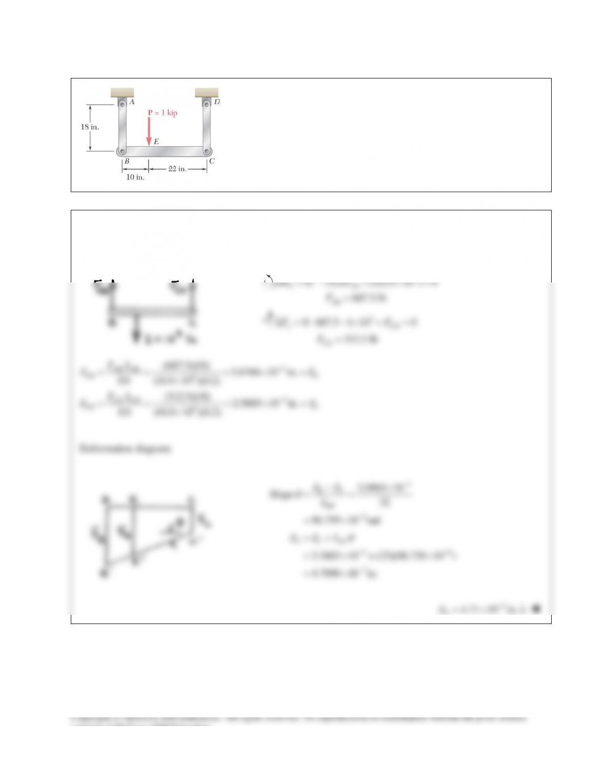
PROBLEM 9.23
Each of the links AB and CD is made of aluminum
6
( 10.9 10 psi)= ×E
and has a cross–sectional area of 0.2 in2. Knowing that they support the
rigid member BC, determine the deflection of point E.
SOLUTION
Free body BC:
3
0: (32) (22)(1 10 ) 0
687.5 lb
Σ=− + × =
=
C AB
AB
MF
F
3
0: 687.5 1 10 0
312.5 lb
y CD
CD
FF
F
Σ = −× + =
=
3
6
3
6
(687.5)(18) 5.6766 10 in.
(10.9 10 )(0.2)
(312.5)(18) 2.5803 10 in.
(10.9 10 )(0.2)
δδ
δδ
−
−
= = =×=
×
= = =×=
×
AB AB
AB B
CD CD
CD C
FL
EA
FL
EA
Deformation diagram:
3
6
3.0963 10
Slope 32
96.759 10 rad
δδ
θ
−
−
−×
= =
= ×
BC
BC
L
36
3
2.5803 10 (22)(96.759 10 )
4.7090 10 in.
δδ θ
−−
−
= +
= ×+ ×
= ×
E C EC
L
3
4.71 10 in.
E
δ
−
=×↓
consent of McGraw–Hill Education.
PROBLEM 9.24
Link BD is made of brass
( 105 GPa)E=
and has a cross–sectional area of
240 mm2. Link CE is made of aluminum
( 72 GPa)E=
and has a cross–
sectional area of 300 mm2. Knowing that they support rigid member ABC,
determine the maximum force P that can be applied vertically at point A if
the deflection of A is not to exceed 0.35 mm.
SOLUTION
Free body member AC:
0: 0.350 0.225 0
1.55556
Σ= − =
=
C BD
BD
M PF
FP
0: 0.125 0.225 0
0.55556
Σ= − =
=
B CE
CE
M PF
FP
9
96
9
96
(1.55556 )(0.225) 13.8889 10
(105 10 )(240 10 )
(0.55556 )(0.150) 3.8581 10
(72 10 )(300 10 )
BD BD
B BD BD BD
CE CE
C CE CE CE
FL PP
EA
FL PP
EA
δδ
δδ
−
−
−
−
= = = = ×
××
= = = = ×
××
Deformation Diagram:
From the deformation diagram,
Slope:
99
17.7470 10 78.876 10
0.225
δδ
θ
−−
+×
= = = ×
BC
BC
PP
L
99
9
13.8889 10 (0.125)(78.876 10 )
23.748 10
δδ θ
−−
−
= +
= ×+ ×
= ×
A B AB
L
PP
P
Apply displacement limit.
39
0.35 10 m 23.748 10
δ
−−
=×=×
A
P
3
14.7381 10 N
P= ×
14.74 kNP=
consent of McGraw–Hill Education.
PROBLEM 9.25
An axial force of 200 kN is applied to the assembly shown by means of
rigid end plates. Determine (a) the normal stress in the aluminum shell,
(b) the corresponding deformation of the assembly.
SOLUTION
Let Pa = Portion of axial force carried by shell.
PROBLEM 9.26
The length of the assembly shown decreases by 0.40 mm when an axial
force is applied by means of rigid end plates. Determine (a) the magnitude
of the applied force, (b) the corresponding stress in the brass core.
SOLUTION
Let Pa = Portion of axial force carried by shell and Pb = Portion of axial force carried by core.
, or
a aa
a
aa
PL E A
P
EA L
δδ
= =
, or
b bb
b
bb
PL E A
P
EA L
δδ
= =
Thus,
()
a b aa bb
P P P EA EA L
δ
=+= +
with
2 2 32
2 32
[(0.060) (0.025) ] 2.3366 10 m
4
(0.025) 0.49087 10 m
4
a
b
A
A
π
π
−
−
= −=×
= = ×
9 39 3 6
[(70 10 )(2.3366 10 ) (105 10 )(0.49087 10 )] 215.10 10
δδ
−−
=× × +× × = ×PLL
with
0.40 mm, 300 mmL
δ
= =
(a)
63
0.40
(215.10 10 ) 286.8 10 N
300
P=×=×
287 kNP=
(b)
93 6
3
(105 10 )(0.40 10 ) 140 10 Pa
300 10
δ
σ
−
−
××
= = = = ×
×
bb
bb
PE
AL
140.0 MPa=
b
σ
consent of McGraw–Hill Education.
PROBLEM 9.27
The 4.5–ft concrete post is reinforced with six steel bars, each with a
1
8
1
–in. diameter.
Knowing that Es = 29 × 106 psi and Ec = 4.2 × 10⁶ psi, determine the normal stresses
in the steel and in the concrete when a 350–kip axial centric force P is applied to the
post.
SOLUTION
Let
portion of axial force carried by concrete.
portion carried by the six steel rods.
=
=
c
s
P
P
()
c cc
c
cc
s ss
s
ss
c s cc ss
cc ss
PL E A
P
EA L
PL E A
P
EA L
P P P EA EA L
P
L EA EA
δ
δ
δ
δ
δ
δ
ε
= =
= =
=+= +
−
= = +
2 22
2 22
2
34
6 26 2
6
6 (1.125 in.) 5.9641in
44
(18 in.) 5.9641 in
44
248.51in
4.5 ft 54 in.
350 10 lb 2.8767 10
(4.2 10 psi)(248.51 in ) (29 10 psi)(5.9641in )
−
= = =
= −= −
=
= =
−×
= =−×
× +×
ss
c cs
Ad
A dA
L
pp
pp
ε
64
(29 10 psi)( 2.8767 10 ) 8.3424 10 psi
ss
E
sε
−3
==× − ×=− ×
s
s
= −8.34 ksi
6 43
(4.2 10 psi)( 2.8767 10 ) 1.20821 10 psi
−
==× − ×= ×
cc
E
sε
c
s
= −1.208 ksi
consent of McGraw–Hill Education.
PROBLEM 9.28
For the post of Prob. 9.27, determine the maximum centric force that can be applied if the
allowable normal stress is 20 ksi in the steel and 2.4 ksi in the concrete.
PROBLEM 9.27 The 4.5–ft concrete post is reinforced with six steel bars, each with
a
1
8
1
–in. diameter. Knowing that Es = 29 × 106 psi and Ec = 4.2 × 10⁶ psi, determine
the normal stresses in the steel and in the concrete when a 350–kip axial centric force P
is applied to the post.
SOLUTION
Allowable strain in each material:
Steel:
34
6
20 10 psi 6.8966 10
29 10 psi
s
ε
−
×
= = = ×
×
s
ss
E
Concrete:
34
6
2.4 10 psi 5.7143 10
4.2 10 psi
s
ε
−
×
= = = ×
×
c
cc
E
Smaller value governs.
4
5.7143 10
δ
ε
−
= = ×
L
Let
c
P
= Portion of load carried by concrete.
s
P
= Portion of load carried by 6 steel rods.
δ
δ∈
= ∴= =
cc cc cc
cc
PL P EA EA
EA L
δ
δ∈
= ∴= =
ss ss ss
ss
PL P EA EA
EA L
2 22
6
6 (1.125 in.) 5.9641in
44
ππ
= = =
ss
Ad
2 2 2 22
(18 in.) 5.9641in 2.4851 10 in
44
c cs
A dA
ππ
= −= − = ×
∈∈
=+= +
c s cc ss
P P P EA EA
6 22 6 2 4
[(4.2 10 psi)(2.4851 10 in ) (29 10 psi)(5.9641in )](5.7143 10 )
−
= × × +× ×P
5
6.9526 10 lb= ×P
695 kipsP=
consent of McGraw–Hill Education.
PROBLEM 9.29
Three steel rods (E = 29 × 106 psi) support an 8.5–kip load P. Each of the
rods AB and CD has a 0.32–in2 cross–sectional area and rod EF has a 1–in2
cross–sectional area. Neglecting the deformation of bar BED, determine
(a) the change in length of rod EF, (b) the stress in each rod.
SOLUTION
Use member BED as a free body.
By symmetry, or by
0:∑=
E
M
CD AB
PP=
0: 0
y AB CD EF
F PPPP∑ = + + −=
2AB EF
PP P= +
= = =
CD CD
AB AB EF EF
AB CD EF
AB CD EF
PL
PL PL
EA EA EA
δδδ
Since
and ,
AB CD AB CD AB CD
LL AA
δδ
= = =
B AB D CD E EF
Since member BED is rigid,
EBC
δδδ
= =
0.32 16 0.256
1 20
= ∴=⋅ =⋅=
AB AB EF EF AB EF
AB EF EF EF
AB EF EF AB
PL PL A L
P P PP
EA EA A L
2 2(0.256 ) 1.512
8.5 5.6217 kips
1.512 1.512
0.256(5.6217) 1.43916 kips
= += +=
===
= = =
AB EF EF EF EF
EF
AB CD
PP P P P P
P
P
PP
(a)
3
(5.6217)(16) 0.0031016 in.
(29 10 )(1)
δ
= = =
×
EF EF
EF EF
PL
EA
0.00310 in.
EF
δ
=
(b)
1.43916 4.4974 ksi
0.32
AB
AB CD AB
P
A
ss
= = = =
4.50 ksi
AB CD
ss
= =
5.6217 5.6217 ksi
1
EF
EF EF
P
A
s
= = =
5.62 ksi
EF
s
=
consent of McGraw–Hill Education.
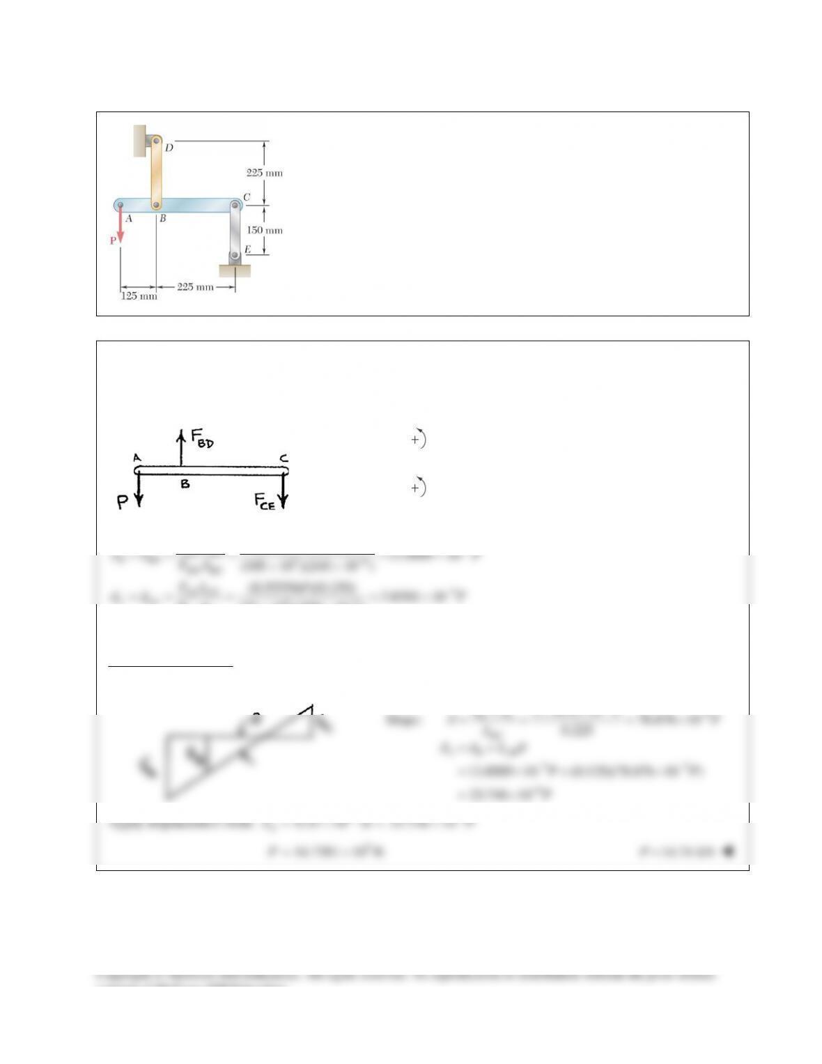
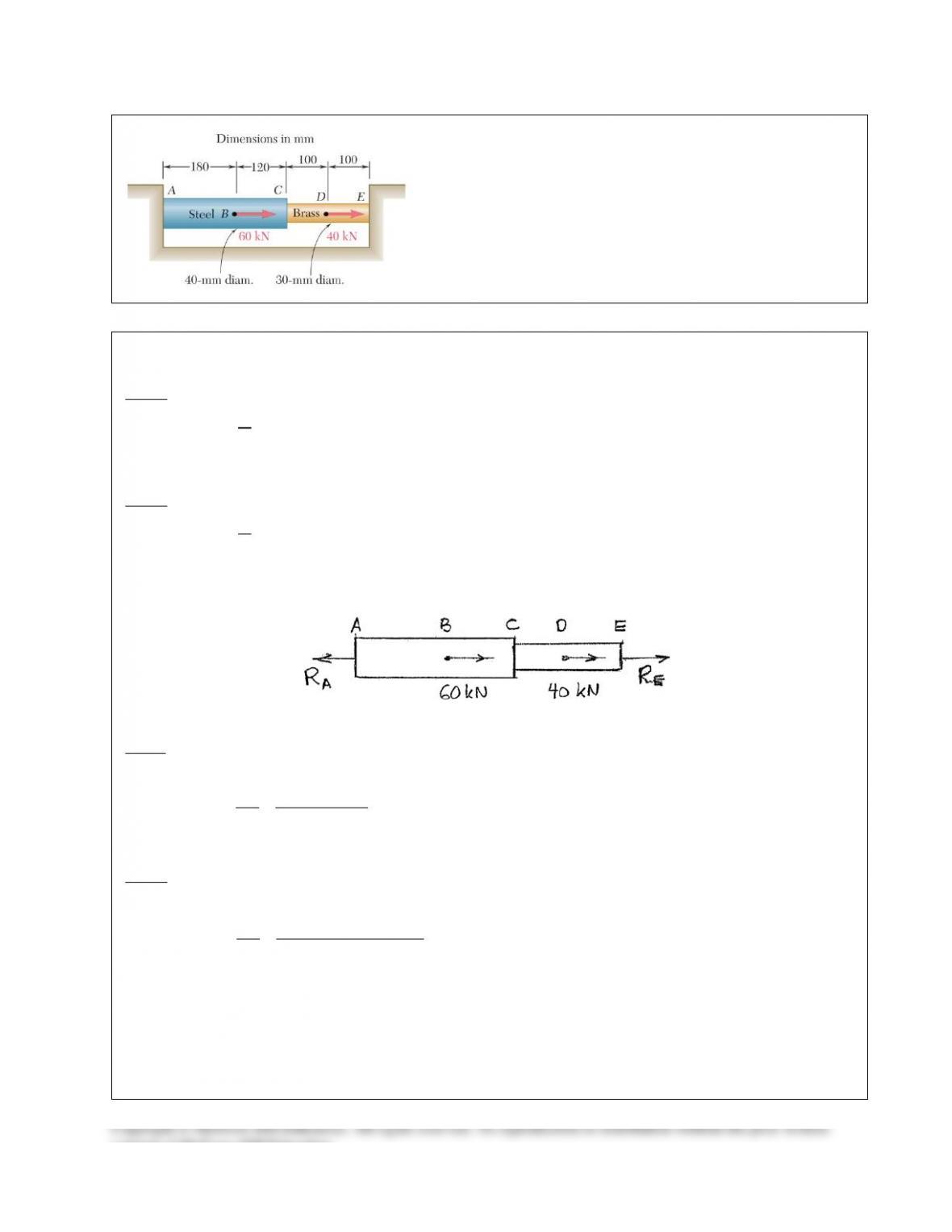
PROBLEM 9.30
Two cylindrical rods, one of steel and the other of brass, are joined at
C and restrained by rigid supports at A and E. For the loading shown
and knowing that
200 GPa
s
E=
and
105 GPa,
b
E=
determine
(a) the reactions at A and E, (b) the deflection of point C.
SOLUTION
A to C:
9
2 3 2 32
6
200 10 Pa
(40) 1.25664 10 mm 1.25664 10 m
4
251.327 10 N
E
A
EA
π
−
= ×
==×=×
= ×
C to E:
9
2 2 62
6
105 10 Pa
(30) 706.86 mm 706.86 10 m
4
74.220 10 N
E
A
EA
π
−
= ×
= = = ×
= ×
A to B:
6
12
180 mm 0.180 m
(0.180)
251.327 10
716.20 10
δ
−
=
= =
= = ×
= ×
A
A
AB
A
PR
L
R
PL
EA
R
B to C:
3
3
6
12 6
60 10
120 mm 0.120 m
( 60 10 )(0.120)
251.327 10
447.47 10 26.848 10
δ
−−
= −×
= =
−×
= = ×
=× −×
A
A
BC
A
PR
L
R
PL
EA
R
consent of McGraw–Hill Education.