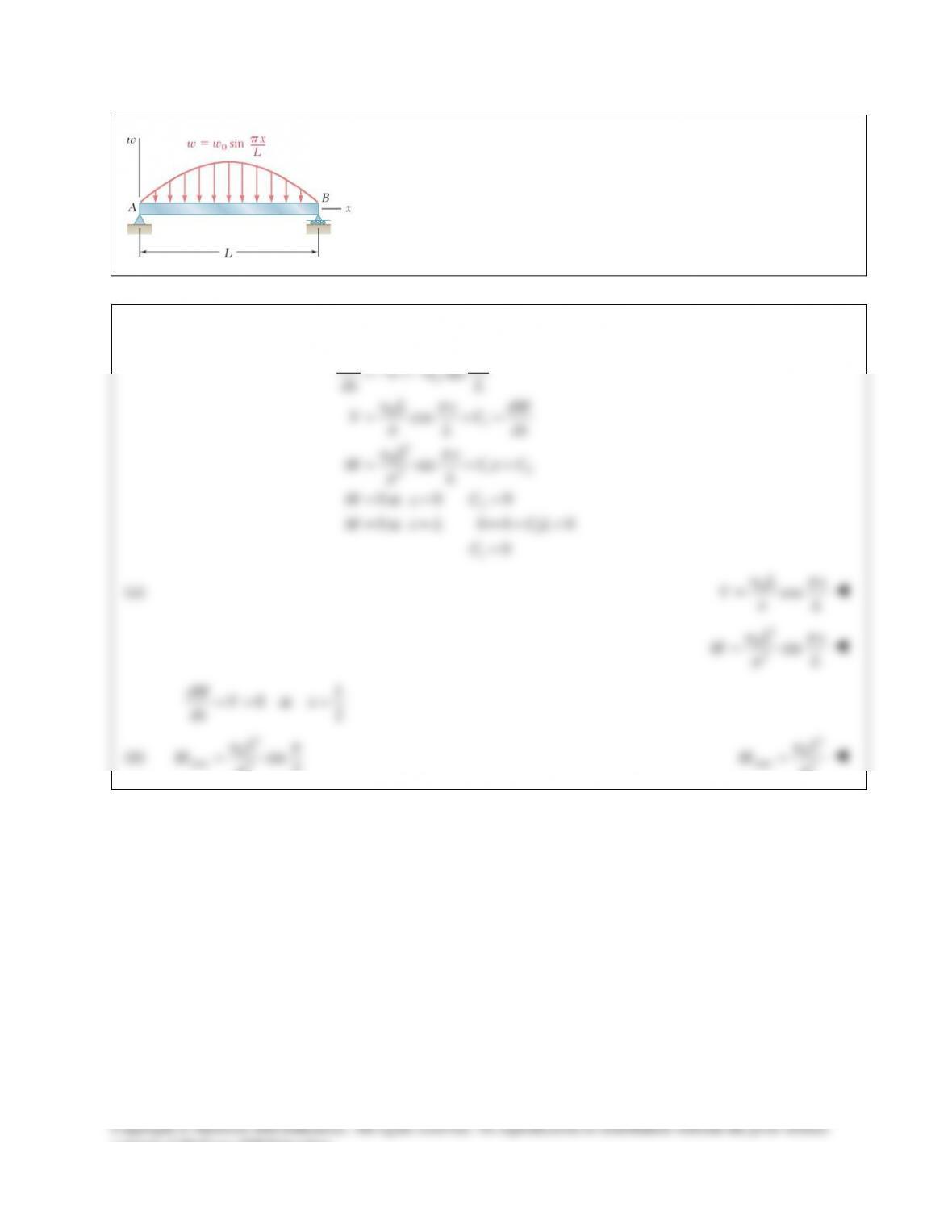
PROBLEM 12.45
Determine (a) the equations of the shear and bending–moment curves for
the beam and loading shown, (b) the maximum absolute value of the
bending moment in the beam.
SOLUTION
0
01
2
012
2
2
1
1
sin
cos
sin
0 at 0 0
0 at 0 0 0
0
dV x
ww
dx L
wL x dM
VC
L dx
wL x
M Cx C
L
MxC
M x L CL
C
π
π
π
π
π
=−=−
= +=
= ++
= = =
= = =++
=
(a)
0cos
wL x
VL
π
π
=
2
02
sin
wL x
ML
π
π
=
0 at 2
dM L
Vx
dx = = =
(b)
2
0
max 2
sin 2
wL
M
π
π
=
2
0
max 2
wL
M
π
=
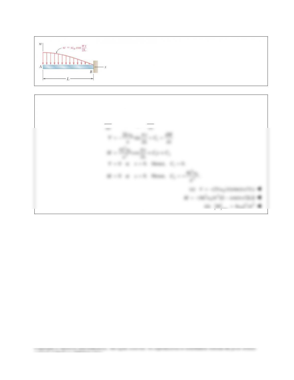
PROBLEM 12.46
Determine (a) the equations of the shear and bending–moment curves for
the beam and loading shown, (b) the maximum absolute value of the
bending moment in the beam.
SOLUTION
0
01
2012
2
1
20
22
cos 2
2sin 2
4cos 2
0 at 0. Hence, 0.
4
0 at 0. Hence, .
dV x
ww
dx L
Lw x dM
VC
L dx
Lw x
M Cx C
L
Vx C
Lw
Mx C
π
π
π
π
π
π
=−=−
=− +=
= ++
= = =
= = = −
(a)
0
(2 / sin( /2 )V Lw x L
ππ
=−)
20
(4 / )[1 cos( /2 )]M Lw x L
ππ
2
=−−
(b)
22
0
max 4/M wL
π
=
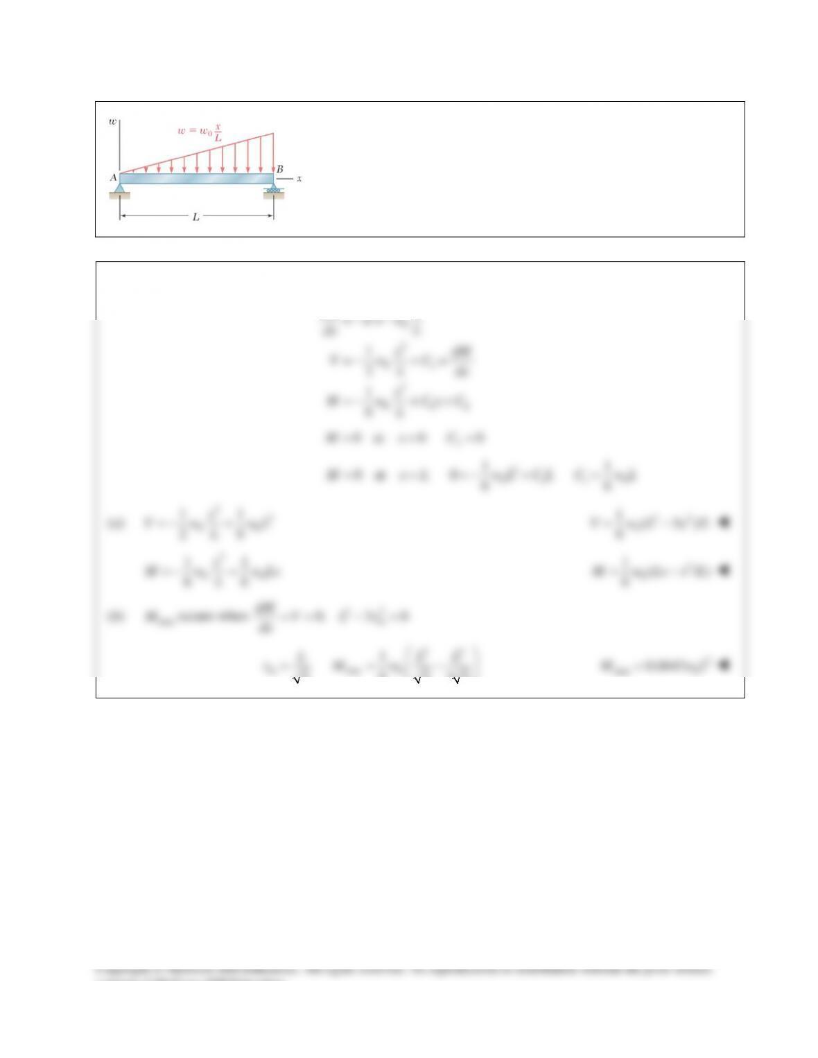
PROBLEM 12.47
Determine (a) the equations of the shear and bending–moment curves for
the beam and loading shown, (b) the maximum absolute value of the
bending moment in the beam.
SOLUTION
0
2
01
3
0 12
1
2
1
6
dV x
ww
dx L
x dM
VwC
L dx
x
M w Cx C
L
=−=−
=− +=
=− ++
2
0 at 0 0M xC= = =
2
01 10
11
0 at 0 66
M x L wL CL C wL= ==−+ =
(a)
22
00
11
26
x
V w wL
L
=−+
22
0
1( 3 )/
6
V wL x L= −
3
00
11
66
x
M w w Lx
L
=−+
3
0
1( /)
6
M w Lx x L= −
(b)
max
M
occurs when
22
0. 3 0
m
dM V Lx
dx == −=
22
max 0
1
6
3 3 33
m
L LL
x Mw
= = −
2
max 0
0.0642M wL=
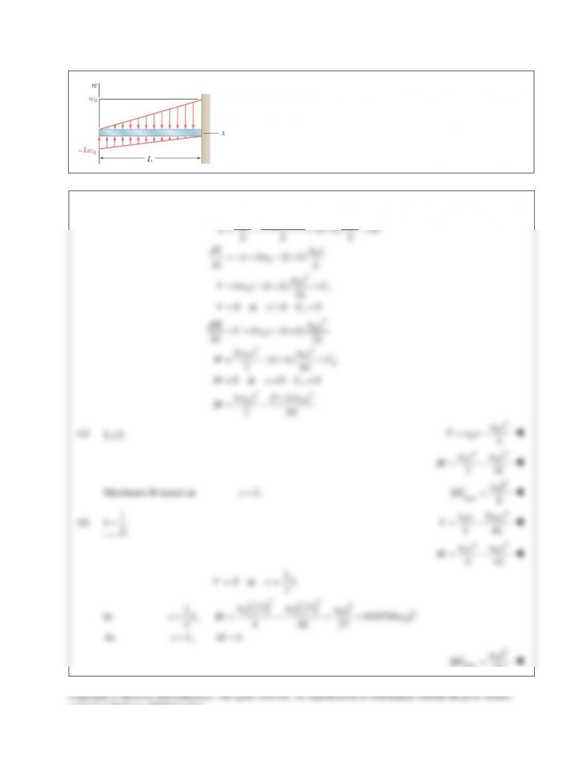
PROBLEM 12.48
For the beam and loading shown, determine the equations of the shear
and bending–moment curves, and the maximum absolute value of the
bending moment in the beam, knowing that (a) k = 1, (b) k = 0.5.
SOLUTION
00 0
0
0
2
0
01
1
2
0
0
()
(1 )
(1 )
(1 ) 2
0 at 0 0
(1 ) 2
wx kw L x wx
w k kw
LL L
wx
dV w kw k
dx L
wx
V kw x k C
L
V xC
wx
dM V kw x k
dx L
−
=− =+−
=−= −+
= −+ +
= = =
== −+
23
00
2
2
23
00
(1 )
26
0 at 0 0
(1 )
26
kwx wx
M kC
L
M xC
kwx kwx
ML
= −+ +
= = =
+
= −
(a)
1.k=
2
0
0wx
V wx L
= −
23
00
23
wx wx
ML
= −
Maximum M occurs at
.xL=
2
0
max
6
wL
M=
(b)
1.
2
k=
2
00
3
24
wx wx
VL
= −
23
00
44
wx wx
ML
= −
2
0 at 3
V xL= =
At
( ) ( )
23
22
2
00
33 2
00
2, 0.03704
3 4 4 27
wL wL wL
x L M wL
L
= =−==
At
,0xL M= =
0
0
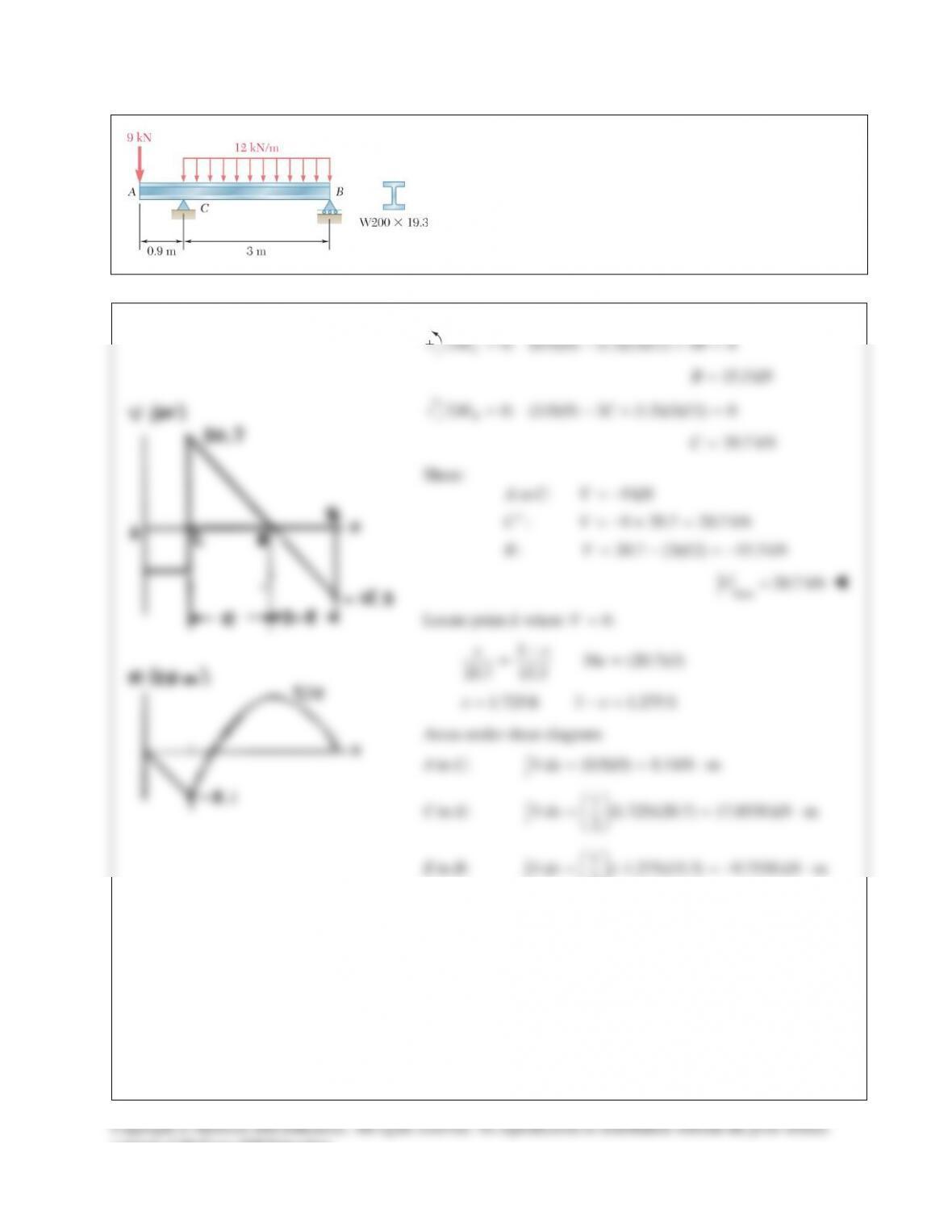
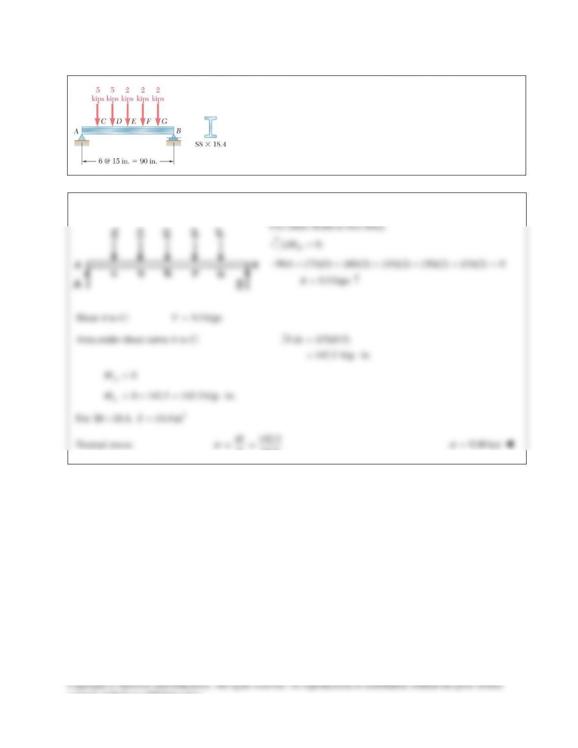
PROBLEM 12.49
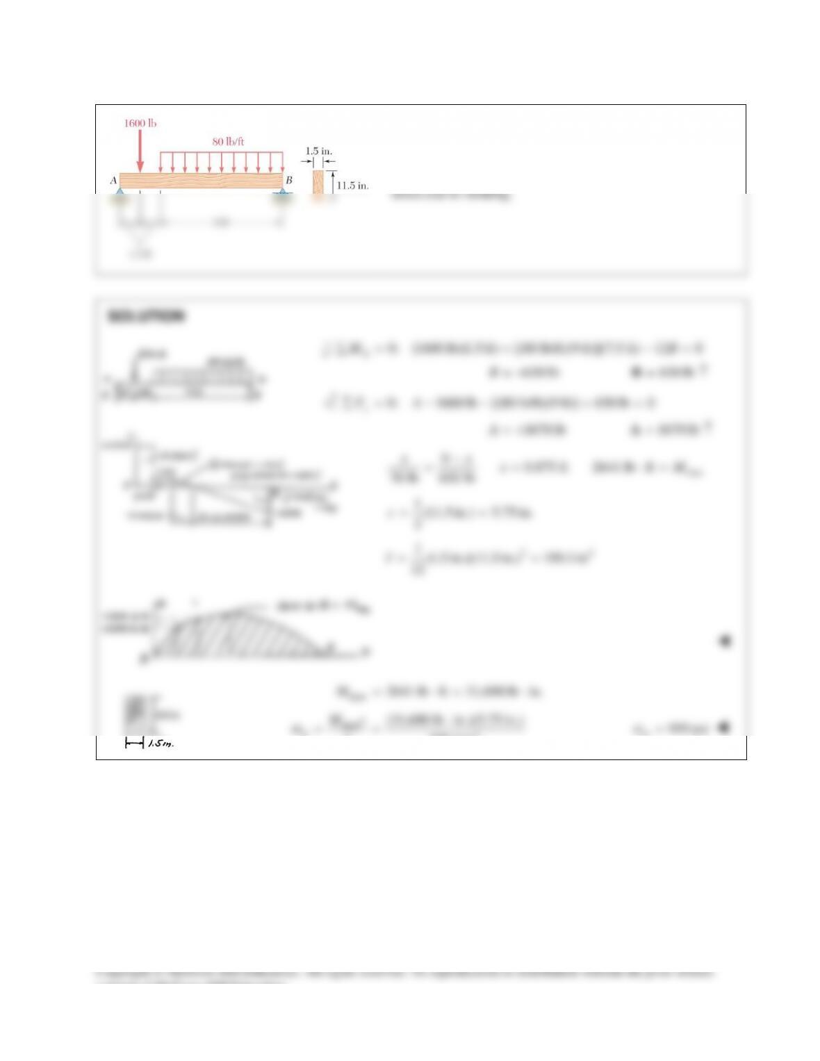
Draw the shear and bending–moment diagrams for the beam
and loading shown and determine the maximum normal
stress due to bending.
SOLUTION
0: (0.9)(9) (1.5)(3)(12) 3 0
C
MBΣ= − +=
15.3 kNB=
0: (3.9)(9) 3 (1.5)(3)(12) 0
B
MCΣ= −+ =
29.7 kNC=
Shear:
to : 9 kNAC V= −
: 9 29.7 20.7 kNCV
+
=−+ =
: 20.7 (3)(12) 15.3 kNBV=−=−
max
20.7 kNV=
Locate point E where
0.V=
336 (20.7)(3)
20.7 15.3
ee
e
−
= =
1.725 ft 3 1.275 ftee= −=
Areas under shear diagram:
A to C:
(0.9)(9) 8.1kN mV dx = = ⋅
∫
C to E:
1(1.725)(20.7) 17.8538 kN m
2
V dx
= = ⋅
∫
E to B:
1( 1.275)(15.3) 9.7538 kN m
2
V dx
=− =−⋅
∫
consent of McGraw–Hill Education.
PROBLEM 12.49 (Continued)
Bending moments:
0
A
M=
0 8.1 8.1kN m
C
M=−=− ⋅
8.1 17.8538 9.7538 kN m
9.7538 9.7538 0
E
B
M
M
=−+ = ⋅
=−=
3
max
9.75 10 N m at point ME=×⋅
For
W200 19.3×
rolled–steel section,
3 3 63
162 10 mm 162 10 mS
−
=×=×
Normal stress:
36
6
9.7538 10 60.2 10 Pa 60.2 MPa
162 10
M
S
σ
−
×
== =×=
×
60.2 MPa
σ
=
consent of McGraw–Hill Education.
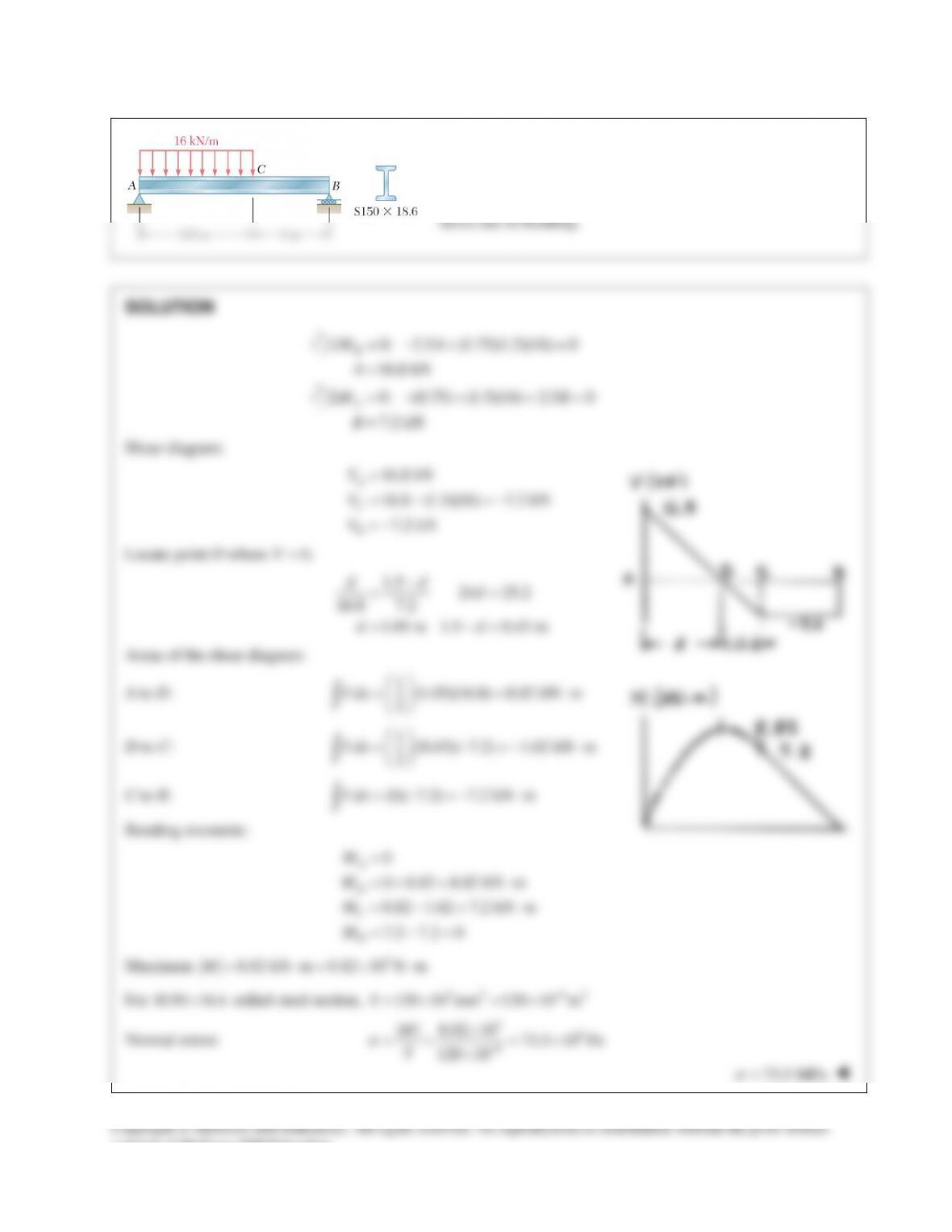
PROBLEM 12.50
Draw the shear and bending–moment diagrams for the beam
and loading shown, and determine the maximum normal
PROBLEM 12.51
Draw the shear and bending–moment diagrams for the beam
and loading shown, and determine the maximum normal
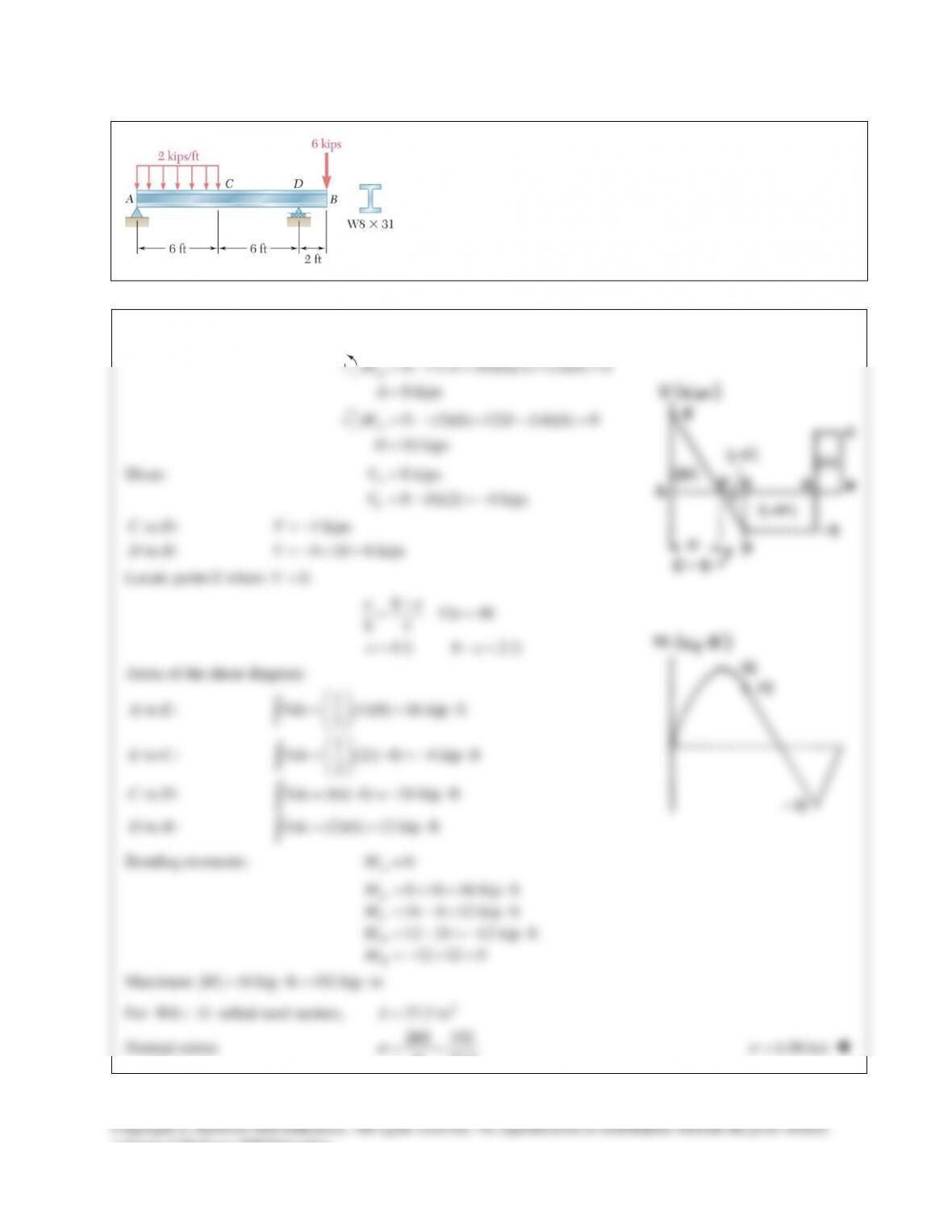
PROBLEM 12.52
Draw the shear and bending–moment diagrams for the beam and
loading shown and determine the maximum normal stress due to
bending.
SOLUTION
0: 12 (9)(6)(2) (2)(6) 0
8 kips
D
MA
A
=−+ − =
=
0: (3)(6) 12 (14)(6) 0
10 kips
A
MD
D
=− +− =
=
Shear:
8 kips
8 (6)(2) 4 kips
A
C
V
V
=
=−=−
to : 4 kips
to : 4 10 6 kips
CD V
DB V
= −
=−+ =
Locate point E where
0.V=
612 48
84
4 ft 6 2 ft
ee
e
ee
−
= =
= −=
Areas of the shear diagram:
1
to : (4)(8) 16 kip ft
2
1
to : (2)( 4) 4 kip ft
2
to : (6)( 4) 24 kip ft
to : (2)(6) 12 kip ft
A E Vdx
E C Vdx
C D Vdx
D B Vdx
= = ⋅
= −=− ⋅
= −=− ⋅
= = ⋅
∫
∫
∫
∫
Bending moments:
0
A
M=
0 16 16 kip ft
16 4 12 kip ft
12 24 12 kip ft
12 12 0
E
C
D
B
M
M
M
M
=+= ⋅
= −= ⋅
=−=− ⋅
=−+ =
Maximum
| | 16 kip ft 192 kip inM= ⋅= ⋅
For
W8 31×
rolled steel section,
3
27.5 inS=
Normal stress:
| | 192
27.5
M
S
σ
= =
6.98 ksi
σ
=
consent of McGraw–Hill Education.
PROBLEM 12.45
Determine (a) the equations of the shear and bending–moment curves for
the beam and loading shown, (b) the maximum absolute value of the
bending moment in the beam.
SOLUTION
0
01
2
012
2
2
1
1
sin
cos
sin
0 at 0 0
0 at 0 0 0
0
dV x
ww
dx L
wL x dM
VC
L dx
wL x
M Cx C
L
MxC
M x L CL
C
π
π
π
π
π
=−=−
= +=
= ++
= = =
= = =++
=
(a)
0cos
wL x
VL
π
π
=
2
02
sin
wL x
ML
π
π
=
0 at 2
dM L
Vx
dx = = =
(b)
2
0
max 2
sin 2
wL
M
π
π
=
2
0
max 2
wL
M
π
=
PROBLEM 12.46
Determine (a) the equations of the shear and bending–moment curves for
the beam and loading shown, (b) the maximum absolute value of the
bending moment in the beam.
SOLUTION
0
01
2012
2
1
20
22
cos 2
2sin 2
4cos 2
0 at 0. Hence, 0.
4
0 at 0. Hence, .
dV x
ww
dx L
Lw x dM
VC
L dx
Lw x
M Cx C
L
Vx C
Lw
Mx C
π
π
π
π
π
π
=−=−
=− +=
= ++
= = =
= = = −
(a)
0
(2 / sin( /2 )V Lw x L
ππ
=−)
20
(4 / )[1 cos( /2 )]M Lw x L
ππ
2
=−−
(b)
22
0
max 4/M wL
π
=
PROBLEM 12.47
Determine (a) the equations of the shear and bending–moment curves for
the beam and loading shown, (b) the maximum absolute value of the
bending moment in the beam.
SOLUTION
0
2
01
3
0 12
1
2
1
6
dV x
ww
dx L
x dM
VwC
L dx
x
M w Cx C
L
=−=−
=− +=
=− ++
2
0 at 0 0M xC= = =
2
01 10
11
0 at 0 66
M x L wL CL C wL= ==−+ =
(a)
22
00
11
26
x
V w wL
L
=−+
22
0
1( 3 )/
6
V wL x L= −
3
00
11
66
x
M w w Lx
L
=−+
3
0
1( /)
6
M w Lx x L= −
(b)
max
M
occurs when
22
0. 3 0
m
dM V Lx
dx == −=
22
max 0
1
6
3 3 33
m
L LL
x Mw
= = −
2
max 0
0.0642M wL=
PROBLEM 12.48
For the beam and loading shown, determine the equations of the shear
and bending–moment curves, and the maximum absolute value of the
bending moment in the beam, knowing that (a) k = 1, (b) k = 0.5.
SOLUTION
00 0
0
0
2
0
01
1
2
0
0
()
(1 )
(1 )
(1 ) 2
0 at 0 0
(1 ) 2
wx kw L x wx
w k kw
LL L
wx
dV w kw k
dx L
wx
V kw x k C
L
V xC
wx
dM V kw x k
dx L
−
=− =+−
=−= −+
= −+ +
= = =
== −+
23
00
2
2
23
00
(1 )
26
0 at 0 0
(1 )
26
kwx wx
M kC
L
M xC
kwx kwx
ML
= −+ +
= = =
+
= −
(a)
1.k=
2
0
0wx
V wx L
= −
23
00
23
wx wx
ML
= −
Maximum M occurs at
.xL=
2
0
max
6
wL
M=
(b)
1.
2
k=
2
00
3
24
wx wx
VL
= −
23
00
44
wx wx
ML
= −
2
0 at 3
V xL= =
At
( ) ( )
23
22
2
00
33 2
00
2, 0.03704
3 4 4 27
wL wL wL
x L M wL
L
= =−==
At
,0xL M= =
PROBLEM 12.49
Draw the shear and bending–moment diagrams for the beam
and loading shown and determine the maximum normal
stress due to bending.
SOLUTION
0: (0.9)(9) (1.5)(3)(12) 3 0
C
MBΣ= − +=
15.3 kNB=
0: (3.9)(9) 3 (1.5)(3)(12) 0
B
MCΣ= −+ =
29.7 kNC=
Shear:
to : 9 kNAC V= −
: 9 29.7 20.7 kNCV
+
=−+ =
: 20.7 (3)(12) 15.3 kNBV=−=−
max
20.7 kNV=
Locate point E where
0.V=
336 (20.7)(3)
20.7 15.3
ee
e
−
= =
1.725 ft 3 1.275 ftee= −=
Areas under shear diagram:
A to C:
(0.9)(9) 8.1kN mV dx = = ⋅
∫
C to E:
1(1.725)(20.7) 17.8538 kN m
2
V dx
= = ⋅
∫
E to B:
1( 1.275)(15.3) 9.7538 kN m
2
V dx
=− =−⋅
∫
consent of McGraw–Hill Education.
PROBLEM 12.49 (Continued)
Bending moments:
0
A
M=
0 8.1 8.1kN m
C
M=−=− ⋅
8.1 17.8538 9.7538 kN m
9.7538 9.7538 0
E
B
M
M
=−+ = ⋅
=−=
3
max
9.75 10 N m at point ME=×⋅
For
W200 19.3×
rolled–steel section,
3 3 63
162 10 mm 162 10 mS
−
=×=×
Normal stress:
36
6
9.7538 10 60.2 10 Pa 60.2 MPa
162 10
M
S
σ
−
×
== =×=
×
60.2 MPa
σ
=
consent of McGraw–Hill Education.
PROBLEM 12.50
Draw the shear and bending–moment diagrams for the beam
and loading shown, and determine the maximum normal
PROBLEM 12.51
Draw the shear and bending–moment diagrams for the beam
and loading shown, and determine the maximum normal
PROBLEM 12.52
Draw the shear and bending–moment diagrams for the beam and
loading shown and determine the maximum normal stress due to
bending.
SOLUTION
0: 12 (9)(6)(2) (2)(6) 0
8 kips
D
MA
A
=−+ − =
=
0: (3)(6) 12 (14)(6) 0
10 kips
A
MD
D
=− +− =
=
Shear:
8 kips
8 (6)(2) 4 kips
A
C
V
V
=
=−=−
to : 4 kips
to : 4 10 6 kips
CD V
DB V
= −
=−+ =
Locate point E where
0.V=
612 48
84
4 ft 6 2 ft
ee
e
ee
−
= =
= −=
Areas of the shear diagram:
1
to : (4)(8) 16 kip ft
2
1
to : (2)( 4) 4 kip ft
2
to : (6)( 4) 24 kip ft
to : (2)(6) 12 kip ft
A E Vdx
E C Vdx
C D Vdx
D B Vdx
= = ⋅
= −=− ⋅
= −=− ⋅
= = ⋅
∫
∫
∫
∫
Bending moments:
0
A
M=
0 16 16 kip ft
16 4 12 kip ft
12 24 12 kip ft
12 12 0
E
C
D
B
M
M
M
M
=+= ⋅
= −= ⋅
=−=− ⋅
=−+ =
Maximum
| | 16 kip ft 192 kip inM= ⋅= ⋅
For
W8 31×
rolled steel section,
3
27.5 inS=
Normal stress:
| | 192
27.5
M
S
σ
= =
6.98 ksi
σ
=
consent of McGraw–Hill Education.