PROBLEM 16.31
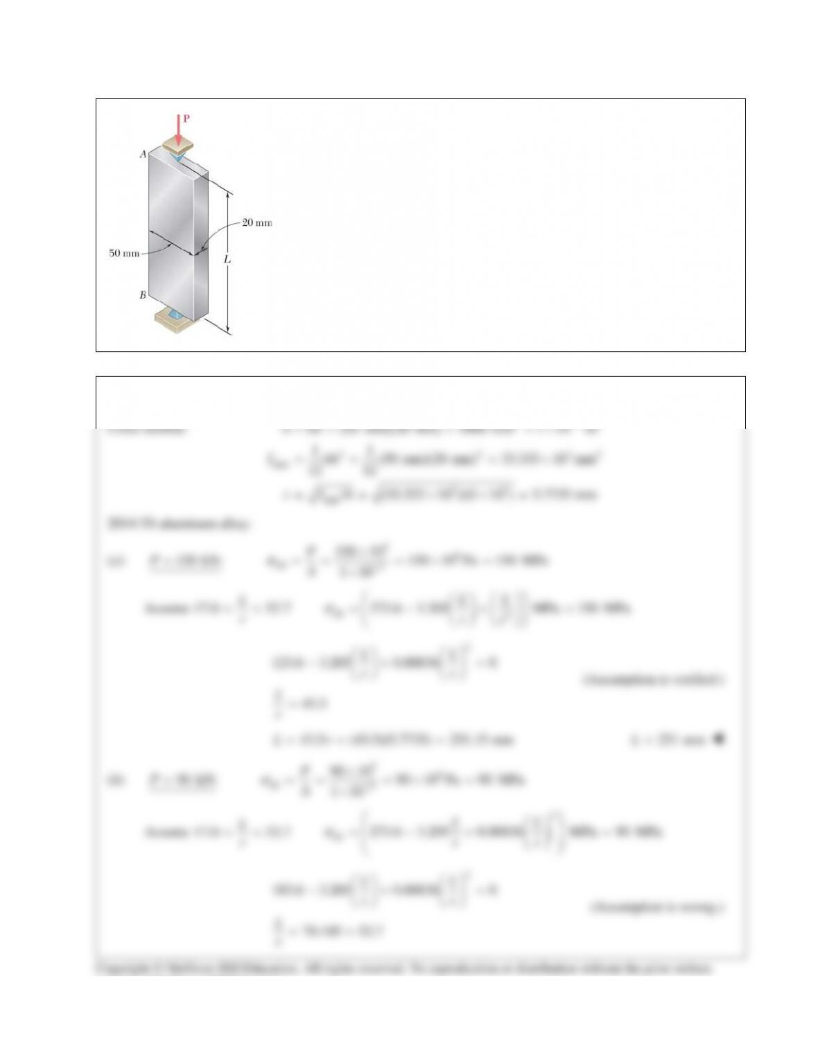
Using the aluminum alloy 2014–T6, determine the largest allowable length of
the aluminum bar AB for a centric load P of magnitude (a) 150 kN,
(b) 90 kN, (c)25 kN.
SOLUTION
2 32
−
consent of McGraw–Hill Education.
PROBLEM 16.31 (Continued)
3
all 2
356 10 MPa 90 MPa
( /)
62.893
Lr
L
r
σ
×
= =
=
(62.893)(5.7735) 363.11 mmL= =
363 mmL=
(c)
25 kN:P=
36
all 3
25 10 25 10 Pa 25 MPa
1 10
P
A
σ
−
×
== =×=
×
For
/ 52.7Lr>
,
3
all 2
356 10 MPa
( /)Lr
σ
×
=
3
356 10
/ 119.331
25
Lr ×
= =
(119.331)(5.7735) 688.96 mmL= =
689 mm
L=
consent of McGraw–Hill Education.
PROBLEM 16.32
A compression member has the cross section shown and an effective length of
5 ft. Knowing that the aluminum alloy used is 6061–T6, determine the allowable
centric load.
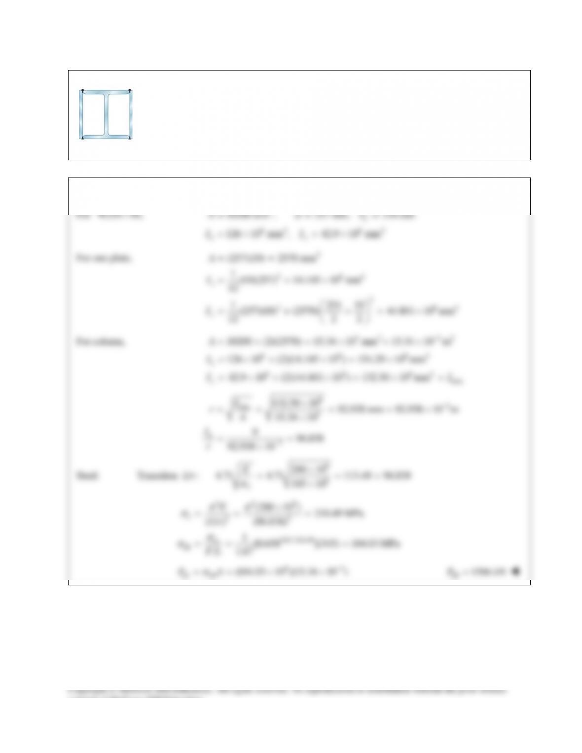
PROBLEM 16.33
A compression member of 9–m effective length is obtained by welding two 10–mm–thick
steel plates to a
W250 80×
rolled–steel shape as shown. Knowing that
345 MPa
Y
σ
=
and
200 GPa=E
and using allowable stress design, determine the allowable centric load for the
compression member.
SOLUTION
For
W250 80,×
2
64 64
10200 mm , 257 mm, 254 mm
126 10 mm , 42.9 10 mm
f
xy
A db
II
= = =
=×=×
For one plate,
4
3 64
2
3 64
(257)(10) 2570 mm
1(10)(257) 14.145 10 mm
12
1 254 10
(257)(10) (2570) 44.801 10 mm
12 2 2
x
y
A
I
I
= =
= = ×
= + += ×
For column,
3 2 32
6 6 64
6 6 64min
10200 (2)(2570) 15.34 10 mm 15.34 10 m
126 10 (2)(14.145 10 ) 154.29 10 mm
42.9 10 (2)(44.801 10 ) 132.50 10 mm
x
y
A
I
II
−
=+ =×=×
=×+ × = ×
= ×+ × = × =
63
min 3
3
132.50 10 92.938 mm 92.938 10 m
15.34 10
996.838
92.938 10
e
I
rA
L
r
−
−
×
= = = = ×
×
= =
×
Steel: Transition
/:Lr
9
6
200 10
4.71 4.71 113.40 96.838
345 10
Y
E
σ
×
= = >
×
22 9
22
345/ 210.49
cr
all
(200 10 ) 210.49 MPa
( / ) (96.838)
1[0.658 ](345) 104.03 MPa
. . 1.67
e
E
Lr
FS
ππ
σ
σ
σ
×
= = =
= = =
63
all all (104.03 10 )(15.34 10 )PA
σ
−
==××
all 1596 kN
P=
consent of McGraw–Hill Education.
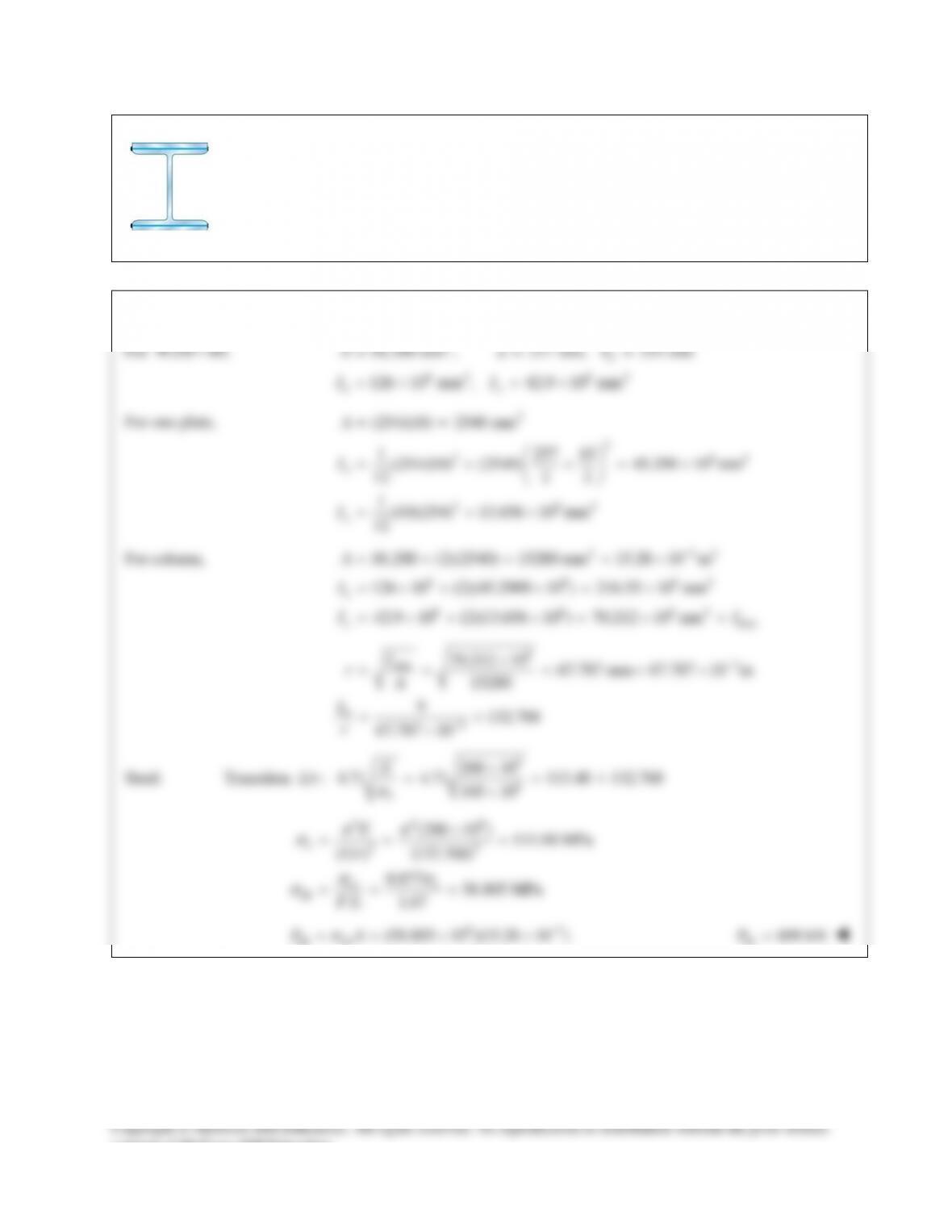
PROBLEM 16.34
A compression member of 9–m effective length is obtained by welding two 10–mm–thick steel
plates to a
W250 80×
rolled–steel shape as shown. Knowing that
345 MPa
Y
σ
=
and
200 GPaE=
and using allowable stress design, determine the allowable centric load for the
compression member.
SOLUTION
For
W250 80,×
2
64 64
10,200 mm , 257 mm, 254 mm
126 10 mm , 42.9 10 mm
f
xy
A db
II
= = =
=×=×
For one plate,
2
2
3 64
3 64
(254)(10) 2540 mm
1 257 10
(254)(10) (2540) 45.290 10 mm
12 2 2
1(10)(254) 13.656 10 mm
12
x
y
A
I
I
= =
= + += ×
= = ×
For column,
2 32
6 6 64
6 6 64min
10,200 (2)(2540) 15280 mm 15.28 10 m
126 10 (2)(45.2900 10 ) 216.55 10 mm
42.9 10 (2)(13.656 10 ) 70.212 10 mm
x
y
A
I
II
−
=+= =×
=×+ × = ×
= ×+ × = × =
63
min
3
70.212 10 67.787 mm 67.787 10 m
15280
9132.768
67.787 10
e
I
rA
L
r
−
−
×
= = = = ×
= =
×
Steel: Transition
/:Lr
9
6
200 10
4.71 4.71 113.40 < 132.768
345 10
Y
E
σ
×
= =
×
22 9
22
cr
all
(200 10 ) 111.98 MPa
( / ) (132.768)
0.877 58.805 MPa
. . 1.67
e
e
E
Lr
FS
ππ
σ
σσ
σ
×
= = =
= = =
63
all all
(58.805 10 )(15.28 10 )PA
σ
−
==××
all
899 kNP=
consent of McGraw–Hill Education.
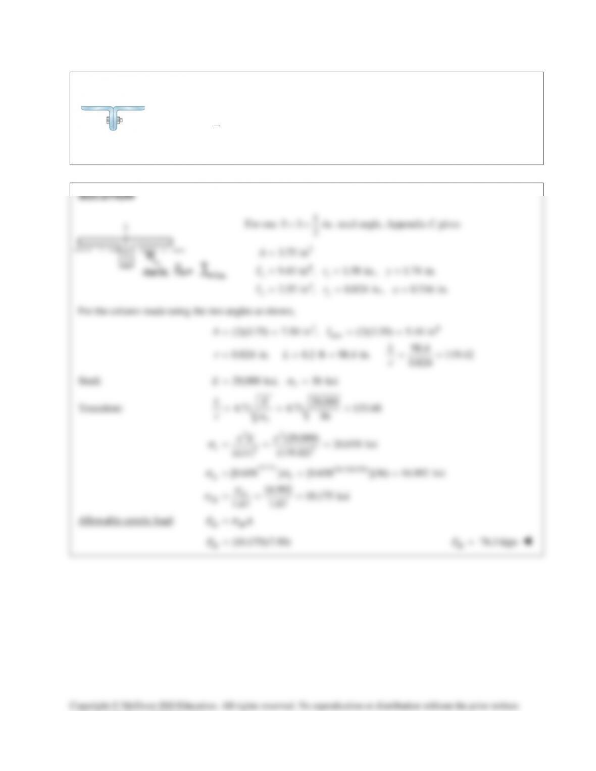
PROBLEM 16.35
A compression member of 8.2–ft effective length is obtained by bolting together
two
1
2
L5 3 -in.××
steel angles as shown. Using allowable stress design, determine the
allowable centric load for the column. Use
36 ksi
Y
s
=
and
6
29 10 psi.E= ×
consent of McGraw–Hill Education.
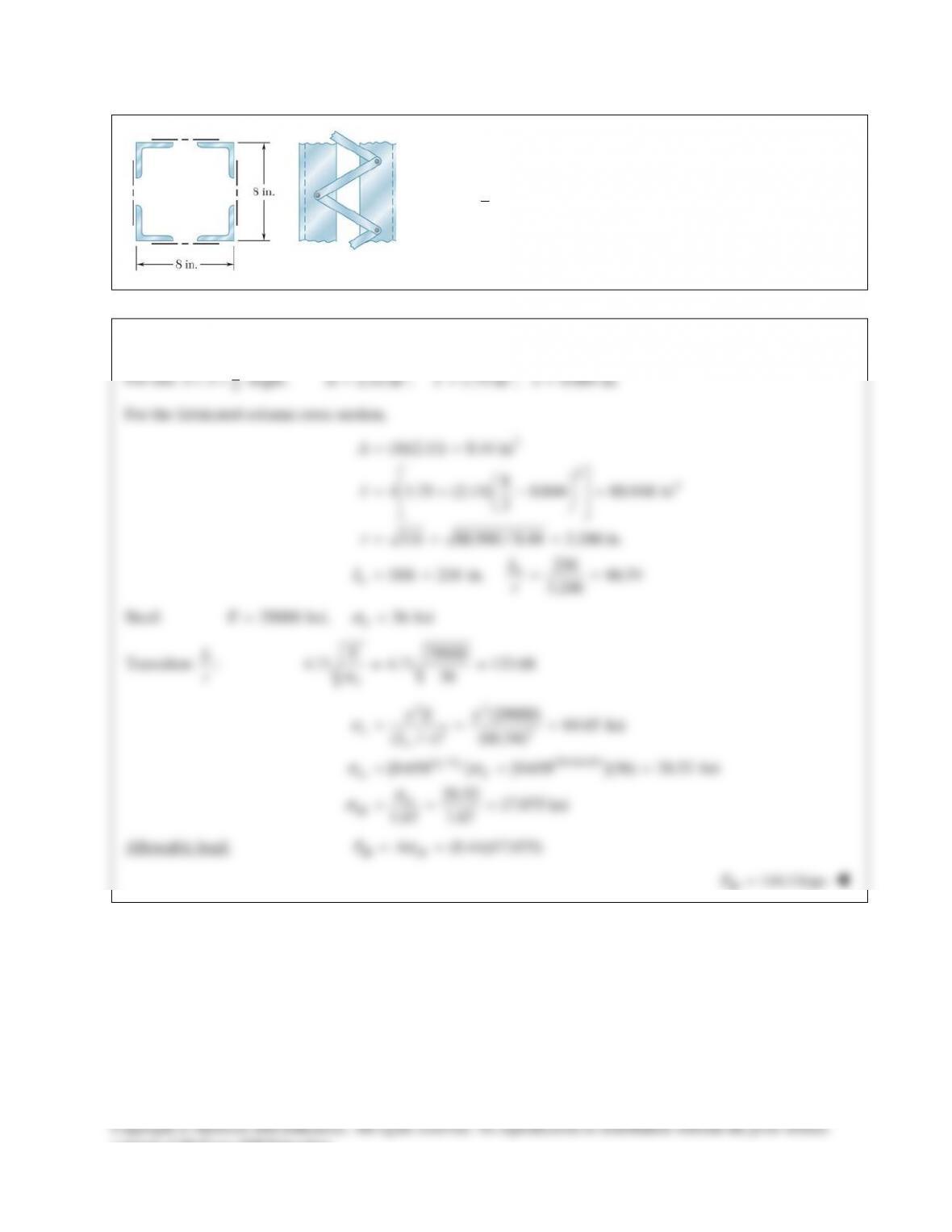
PROBLEM 16.36
A column of 18–ft effective length is obtained by connecting four
3
8
L3 3 -in.××
steel angles with lacing bars as shown. Using
allowable stress design, determine the allowable centric load for
the column. Use
36 ksi
Y
s
=
and
6
29 10 psi.E= ×
SOLUTION
For one
3
8
33××
angle,
24
2.11 in , 1.75 in , 0.884 in.A Ix= = =
For the fabricated column cross section,
2
24
(4)(2.11) 8.44 in
8
4 1.75 (2.11) 0.844 88.948 in
2
/ 88.948 / 8.44 3.246 in.
216
18ft 216 in. 66.54
3.246
e
e
A
I
r IA
L
Lr
= =
=+−=
= = =
= = = =
Steel:
29000 ksi, 36 ksi
Y
E
s
= =
Transition
L
r
:
29000
4.71 4.71 133.68
36
Y
E
s
= =
22
22
/(36/64.65)
cr
cr
all
(29000) 64.65 ksi
( / ) (66.54)
[0.658 ] [0.658 ](36) 28.52 ksi
28.52 17.075 ksi
1.67 1.67
Ye
ee
Y
E
Lr
ss
ππ
s
ss
s
s
= = =
= = =
= = =
Allowable load:
all all (8.44)(17.075)PA
s
= =
all
144.1 kipsP=
consent of McGraw–Hill Education.
PROBLEM 16.37
A rectangular column with a 4.4–m effective length is made of glued
laminated wood. Knowing that for the grade of wood used the adjusted
allowable stress for compression parallel to the grain is
8.3
C
σ
=
MPa and
the adjusted modulus is
4.6 GPa,E=
determine the maximum
allowable centric load for the column.
PROBLEM 16.38
An aluminum structural tube is reinforced by bolting two plates to it
as shown for use as a column of 1.7–m effective length. Knowing
that all material is aluminum alloy 2014-T6, determine the
maximum allowable centric load.
PROBLEM 16.31
Using the aluminum alloy 2014–T6, determine the largest allowable length of
the aluminum bar AB for a centric load P of magnitude (a) 150 kN,
(b) 90 kN, (c)25 kN.
SOLUTION
2 32
−
consent of McGraw–Hill Education.
PROBLEM 16.31 (Continued)
3
all 2
356 10 MPa 90 MPa
( /)
62.893
Lr
L
r
σ
×
= =
=
(62.893)(5.7735) 363.11 mmL= =
363 mmL=
(c)
25 kN:P=
36
all 3
25 10 25 10 Pa 25 MPa
1 10
P
A
σ
−
×
== =×=
×
For
/ 52.7Lr>
,
3
all 2
356 10 MPa
( /)Lr
σ
×
=
3
356 10
/ 119.331
25
Lr ×
= =
(119.331)(5.7735) 688.96 mmL= =
689 mm
L=
consent of McGraw–Hill Education.
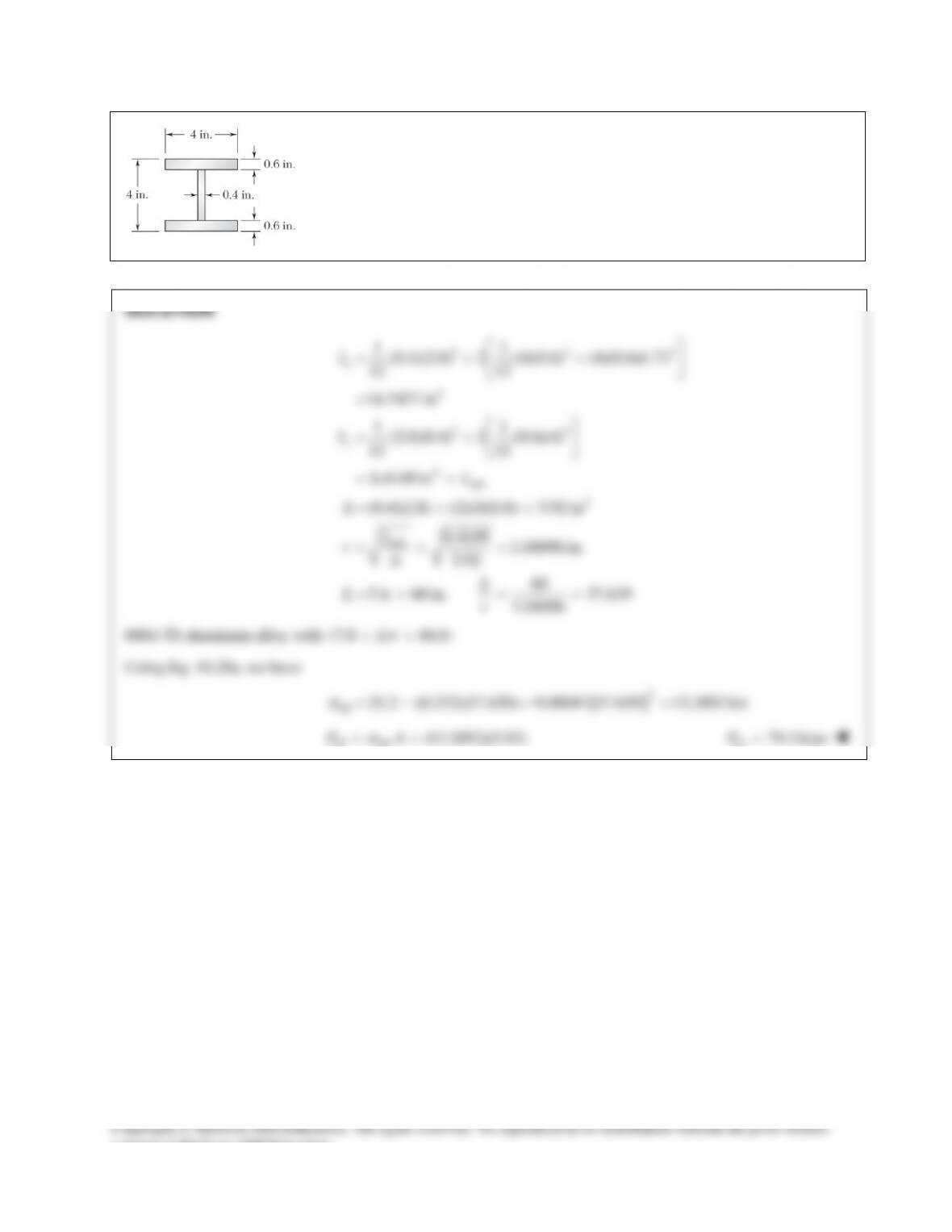
PROBLEM 16.32
A compression member has the cross section shown and an effective length of
5 ft. Knowing that the aluminum alloy used is 6061–T6, determine the allowable
centric load.
PROBLEM 16.33
A compression member of 9–m effective length is obtained by welding two 10–mm–thick
steel plates to a
W250 80×
rolled–steel shape as shown. Knowing that
345 MPa
Y
σ
=
and
200 GPa=E
and using allowable stress design, determine the allowable centric load for the
compression member.
SOLUTION
For
W250 80,×
2
64 64
10200 mm , 257 mm, 254 mm
126 10 mm , 42.9 10 mm
f
xy
A db
II
= = =
=×=×
For one plate,
4
3 64
2
3 64
(257)(10) 2570 mm
1(10)(257) 14.145 10 mm
12
1 254 10
(257)(10) (2570) 44.801 10 mm
12 2 2
x
y
A
I
I
= =
= = ×
= + += ×
For column,
3 2 32
6 6 64
6 6 64min
10200 (2)(2570) 15.34 10 mm 15.34 10 m
126 10 (2)(14.145 10 ) 154.29 10 mm
42.9 10 (2)(44.801 10 ) 132.50 10 mm
x
y
A
I
II
−
=+ =×=×
=×+ × = ×
= ×+ × = × =
63
min 3
3
132.50 10 92.938 mm 92.938 10 m
15.34 10
996.838
92.938 10
e
I
rA
L
r
−
−
×
= = = = ×
×
= =
×
Steel: Transition
/:Lr
9
6
200 10
4.71 4.71 113.40 96.838
345 10
Y
E
σ
×
= = >
×
22 9
22
345/ 210.49
cr
all
(200 10 ) 210.49 MPa
( / ) (96.838)
1[0.658 ](345) 104.03 MPa
. . 1.67
e
E
Lr
FS
ππ
σ
σ
σ
×
= = =
= = =
63
all all (104.03 10 )(15.34 10 )PA
σ
−
==××
all 1596 kN
P=
consent of McGraw–Hill Education.
PROBLEM 16.34
A compression member of 9–m effective length is obtained by welding two 10–mm–thick steel
plates to a
W250 80×
rolled–steel shape as shown. Knowing that
345 MPa
Y
σ
=
and
200 GPaE=
and using allowable stress design, determine the allowable centric load for the
compression member.
SOLUTION
For
W250 80,×
2
64 64
10,200 mm , 257 mm, 254 mm
126 10 mm , 42.9 10 mm
f
xy
A db
II
= = =
=×=×
For one plate,
2
2
3 64
3 64
(254)(10) 2540 mm
1 257 10
(254)(10) (2540) 45.290 10 mm
12 2 2
1(10)(254) 13.656 10 mm
12
x
y
A
I
I
= =
= + += ×
= = ×
For column,
2 32
6 6 64
6 6 64min
10,200 (2)(2540) 15280 mm 15.28 10 m
126 10 (2)(45.2900 10 ) 216.55 10 mm
42.9 10 (2)(13.656 10 ) 70.212 10 mm
x
y
A
I
II
−
=+= =×
=×+ × = ×
= ×+ × = × =
63
min
3
70.212 10 67.787 mm 67.787 10 m
15280
9132.768
67.787 10
e
I
rA
L
r
−
−
×
= = = = ×
= =
×
Steel: Transition
/:Lr
9
6
200 10
4.71 4.71 113.40 < 132.768
345 10
Y
E
σ
×
= =
×
22 9
22
cr
all
(200 10 ) 111.98 MPa
( / ) (132.768)
0.877 58.805 MPa
. . 1.67
e
e
E
Lr
FS
ππ
σ
σσ
σ
×
= = =
= = =
63
all all
(58.805 10 )(15.28 10 )PA
σ
−
==××
all
899 kNP=
consent of McGraw–Hill Education.
PROBLEM 16.35
A compression member of 8.2–ft effective length is obtained by bolting together
two
1
2
L5 3 -in.××
steel angles as shown. Using allowable stress design, determine the
allowable centric load for the column. Use
36 ksi
Y
s
=
and
6
29 10 psi.E= ×
consent of McGraw–Hill Education.
PROBLEM 16.36
A column of 18–ft effective length is obtained by connecting four
3
8
L3 3 -in.××
steel angles with lacing bars as shown. Using
allowable stress design, determine the allowable centric load for
the column. Use
36 ksi
Y
s
=
and
6
29 10 psi.E= ×
SOLUTION
For one
3
8
33××
angle,
24
2.11 in , 1.75 in , 0.884 in.A Ix= = =
For the fabricated column cross section,
2
24
(4)(2.11) 8.44 in
8
4 1.75 (2.11) 0.844 88.948 in
2
/ 88.948 / 8.44 3.246 in.
216
18ft 216 in. 66.54
3.246
e
e
A
I
r IA
L
Lr
= =
=+−=
= = =
= = = =
Steel:
29000 ksi, 36 ksi
Y
E
s
= =
Transition
L
r
:
29000
4.71 4.71 133.68
36
Y
E
s
= =
22
22
/(36/64.65)
cr
cr
all
(29000) 64.65 ksi
( / ) (66.54)
[0.658 ] [0.658 ](36) 28.52 ksi
28.52 17.075 ksi
1.67 1.67
Ye
ee
Y
E
Lr
ss
ππ
s
ss
s
s
= = =
= = =
= = =
Allowable load:
all all (8.44)(17.075)PA
s
= =
all
144.1 kipsP=
consent of McGraw–Hill Education.
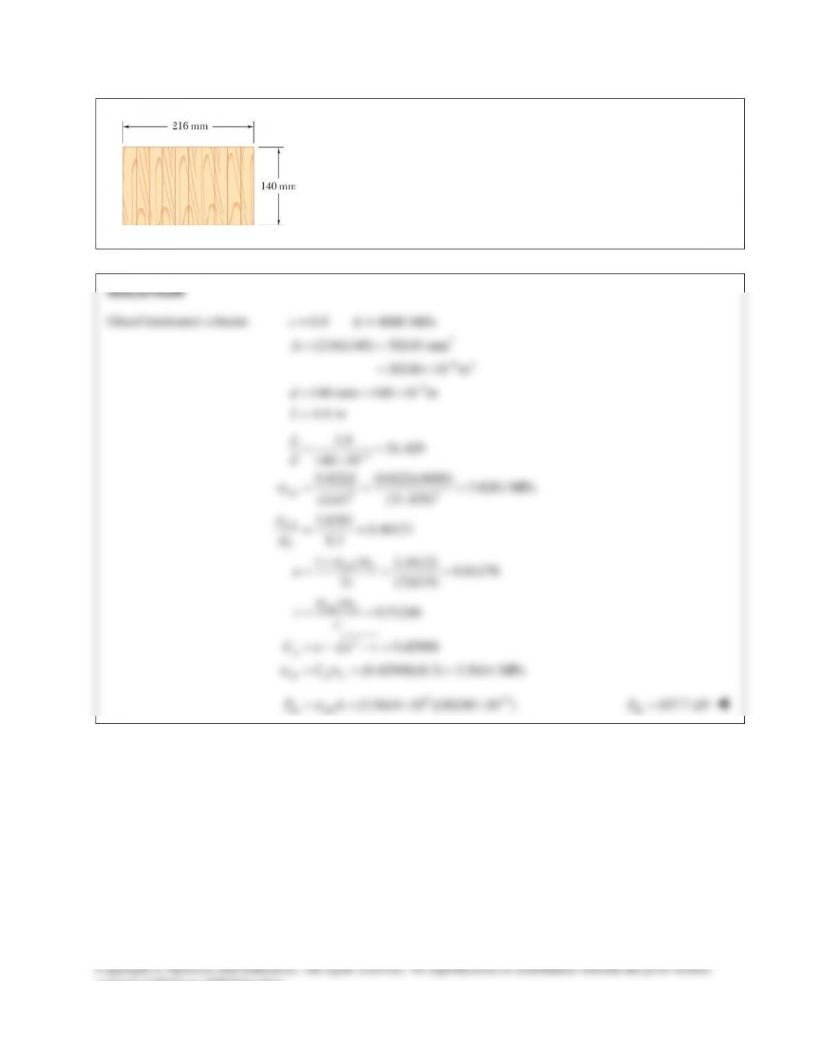
PROBLEM 16.37
A rectangular column with a 4.4–m effective length is made of glued
laminated wood. Knowing that for the grade of wood used the adjusted
allowable stress for compression parallel to the grain is
8.3
C
σ
=
MPa and
the adjusted modulus is
4.6 GPa,E=
determine the maximum
allowable centric load for the column.
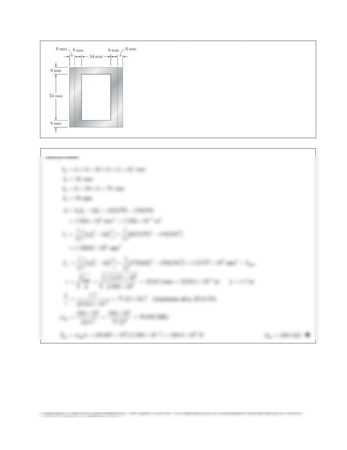
PROBLEM 16.38
An aluminum structural tube is reinforced by bolting two plates to it
as shown for use as a column of 1.7–m effective length. Knowing
that all material is aluminum alloy 2014-T6, determine the
maximum allowable centric load.