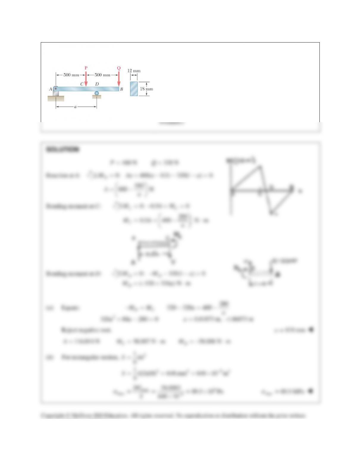
PROBLEM 12.27
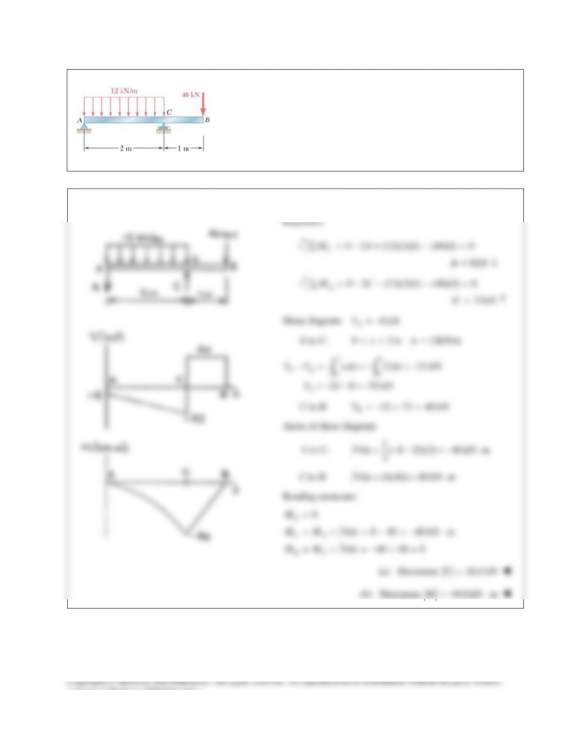
Determine (a) the distance a for which the absolute value of the
bending moment in the beam is as small as possible, (b) the
corresponding maximum normal stress due to bending. (Hint: Draw
the bending–moment diagram and equate the absolute values of the
largest positive and negative bending moments obtained.)
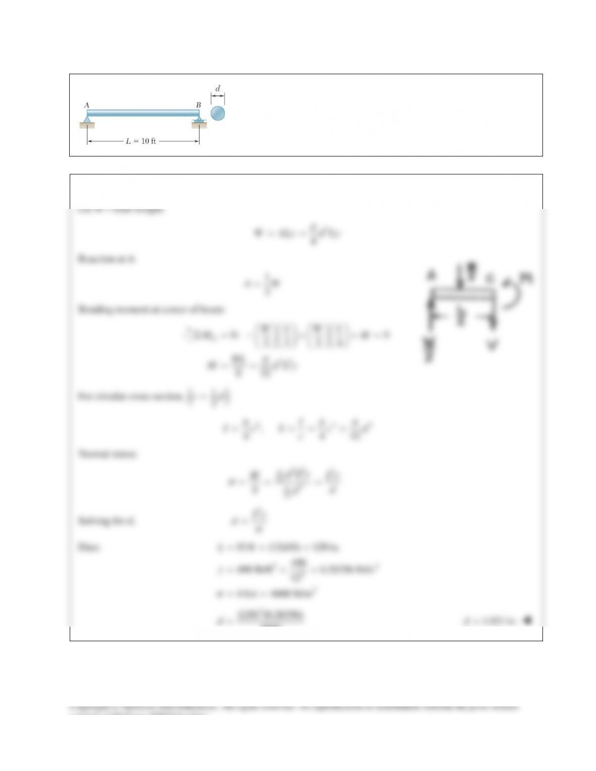
PROBLEM 12.28
A solid steel rod of diameter d is supported as shown. Knowing that for
steel
3
490 lb/ft ,
γ
=
determine the smallest diameter d that can be
used if the normal stress due to bending is not to exceed 4 ksi.
SOLUTION
PROBLEM 12.29
Using the method of Sec. 12.2, solve Prob. 12.1a.
PROBLEM 12.1 For the beam and loading shown, (a) draw the shear and
bending-moment diagrams, (b) determine the equations of the shear and
consent of McGraw–Hill Education.
PROBLEM 12.30
Using the method of Sec. 12.2, solve Prob. 12.2a.
PROBLEM 12.2 For the beam and loading shown, (a) draw the shear and
bending-moment diagrams, (b) determine the equations of the shear and
consent of McGraw–Hill Education.
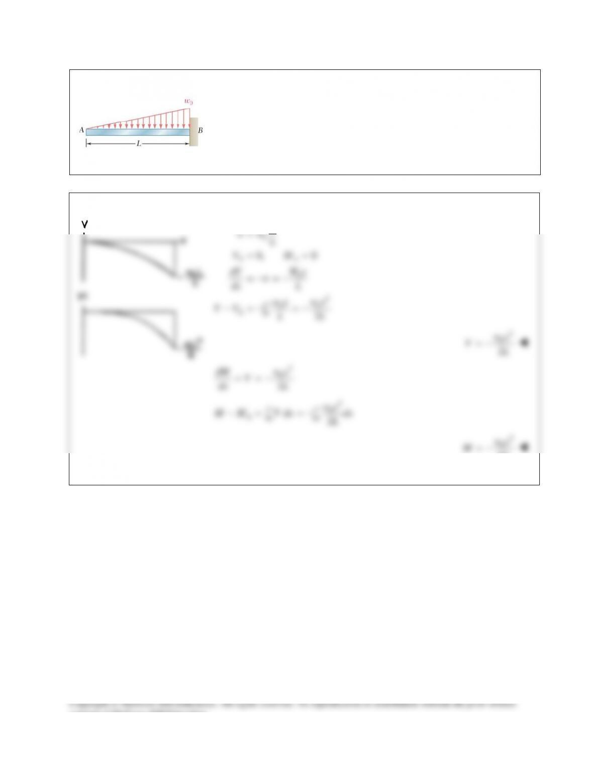
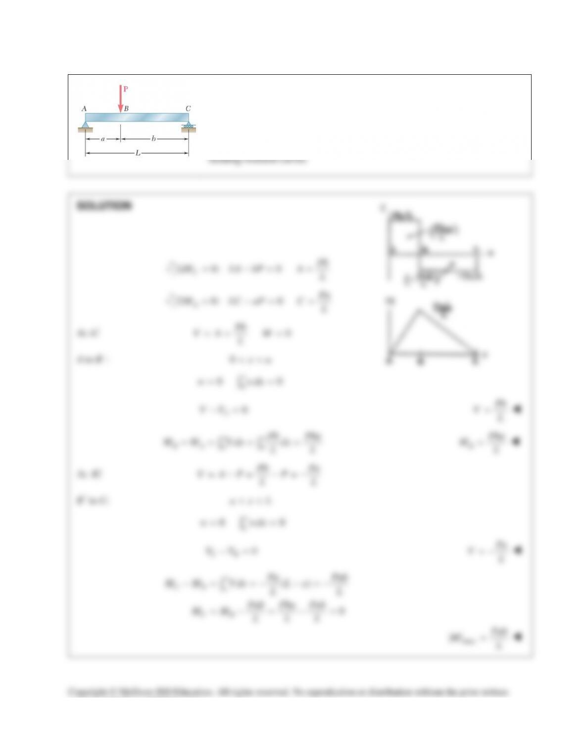
PROBLEM 12.31
Using the method of Sec. 12.2, solve Prob. 12.3a
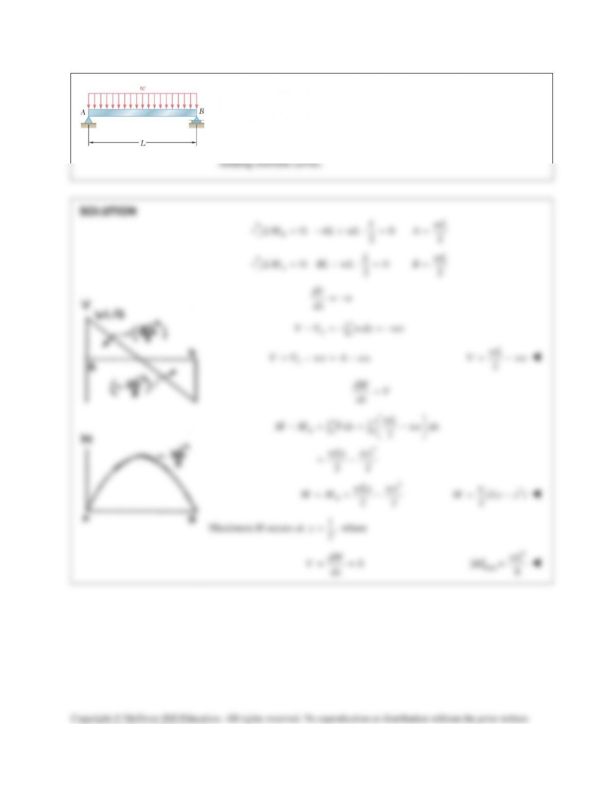
PROBLEM 12.3 For the beam and loading shown, (a) draw the shear and
bending-moment diagrams, (b) determine the equations of the shear and
bending-moment curves.
SOLUTION
0
0
2
00
0
0, 0
2
AA
x
A
x
ww
L
VM
dV W x
w
dx L
wx wx
VV LL
=
= =
=−=−
−=− =−
∫
2
0
2
wx
VL
= −
2
0
2
dM w x
V
dx L
= = −
2
0
00
2
xx
Awx
M M V dx dx
L
−= =−
∫∫
3
0
6
wx
ML
= −
PROBLEM 12.32 (Continued)
At
C.
x La= −
11
( 2) ( 2)
22
CC
V wLaM Laa=−− =−
C
to D.
1( 2)
2
C
V V wL a==−−
0
D
M=
,
2
L
At x =
22
max
82
La
Mw
= −
consent of McGraw–Hill Education.
PROBLEM 12.33
Using the method of Sec. 12.2 solve Prob. 12.5.
PROBLEM 12.5 Draw the shear and bending–moment diagrams for the
beam and loading shown, and determine the maximum absolute value
(a) of the shear, (b) of the bending moment.
SOLUTION
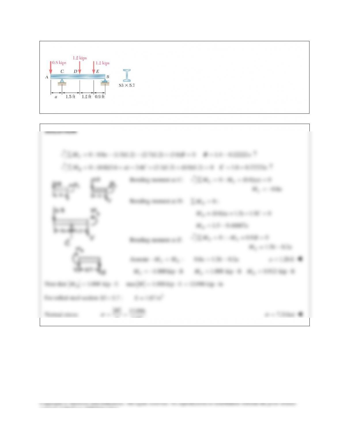
PROBLEM 12.34
Using the method of Sec. 12.2, Solve Prob. 12.6
PROBLEM 12.6 Draw the shear and bending–moment diagram for the
beam and loading shown, and determine the maximum absolute value
(a) of the shear, (b) of the bending moment.
SOLUTION
0 : (0.3)(200) (0.525)(200)
(0.825)(500) (1.05)(200) 0
AA
MM∑= −− −
+ −=
37.5N m
A
M= ⋅
0 : 200 200 500 200 0
yA
FV∑= −−+−=
100N
A
V=
Shear:
A to C:
100NV=
C to D:
100 200 100 NV=−=−
D to E:
100 200 300 NV=−− =−
E to B:
300 500 200NV=−+ =
Areas under shear diagram:
A to C:
(100)(0.3) 30N mVdx = = ⋅
∫
C to D:
( 100)(0.225) 22.5N mVdx =− =−⋅
∫
D to E:
( 300)(0.3) 90 N mVdx =− =−⋅
∫
E to B:
(200)(0.225) 45N mVdx = = ⋅
∫
Bending moments:
37.5N m
A
M= ⋅
37.5 30 67.5N m
C
CA
A
M M V dx= + = += ⋅
∫
67.5 22.5 45N m
D
DC
C
M M V dx=+ =−=⋅
∫
45 90 45N m
E
ED
D
M M V dx
= + =−=− ⋅
∫
45 45 0
D
BE
E
M M V dx= + =−+ =
∫
(a) Maximum
300NV=
(b) Maximum
67.5 N mM= ⋅
consent of McGraw–Hill Education.
PROBLEM 12.35
Using the method of Sec. 12.2, Solve Prob. 12.7
PROBLEM 12.7 Draw the shear and bending–moment diagrams for the
beam and loading shown, and determine the maximum absolute value
(a) of the shear, (b) of the bending moment.
SOLUTION
PROBLEM 12.27
Determine (a) the distance a for which the absolute value of the
bending moment in the beam is as small as possible, (b) the
corresponding maximum normal stress due to bending. (Hint: Draw
the bending–moment diagram and equate the absolute values of the
largest positive and negative bending moments obtained.)
PROBLEM 12.28
A solid steel rod of diameter d is supported as shown. Knowing that for
steel
3
490 lb/ft ,
γ
=
determine the smallest diameter d that can be
used if the normal stress due to bending is not to exceed 4 ksi.
SOLUTION
PROBLEM 12.29
Using the method of Sec. 12.2, solve Prob. 12.1a.
PROBLEM 12.1 For the beam and loading shown, (a) draw the shear and
bending-moment diagrams, (b) determine the equations of the shear and
consent of McGraw–Hill Education.
PROBLEM 12.30
Using the method of Sec. 12.2, solve Prob. 12.2a.
PROBLEM 12.2 For the beam and loading shown, (a) draw the shear and
bending-moment diagrams, (b) determine the equations of the shear and
consent of McGraw–Hill Education.
PROBLEM 12.31
Using the method of Sec. 12.2, solve Prob. 12.3a
PROBLEM 12.3 For the beam and loading shown, (a) draw the shear and
bending-moment diagrams, (b) determine the equations of the shear and
bending-moment curves.
SOLUTION
0
0
2
00
0
0, 0
2
AA
x
A
x
ww
L
VM
dV W x
w
dx L
wx wx
VV LL
=
= =
=−=−
−=− =−
∫
2
0
2
wx
VL
= −
2
0
2
dM w x
V
dx L
= = −
2
0
00
2
xx
Awx
M M V dx dx
L
−= =−
∫∫
3
0
6
wx
ML
= −
PROBLEM 12.32 (Continued)
At
C.
x La= −
11
( 2) ( 2)
22
CC
V wLaM Laa=−− =−
C
to D.
1( 2)
2
C
V V wL a==−−
0
D
M=
,
2
L
At x =
22
max
82
La
Mw
= −
consent of McGraw–Hill Education.
PROBLEM 12.33
Using the method of Sec. 12.2 solve Prob. 12.5.
PROBLEM 12.5 Draw the shear and bending–moment diagrams for the
beam and loading shown, and determine the maximum absolute value
(a) of the shear, (b) of the bending moment.
SOLUTION
PROBLEM 12.34
Using the method of Sec. 12.2, Solve Prob. 12.6
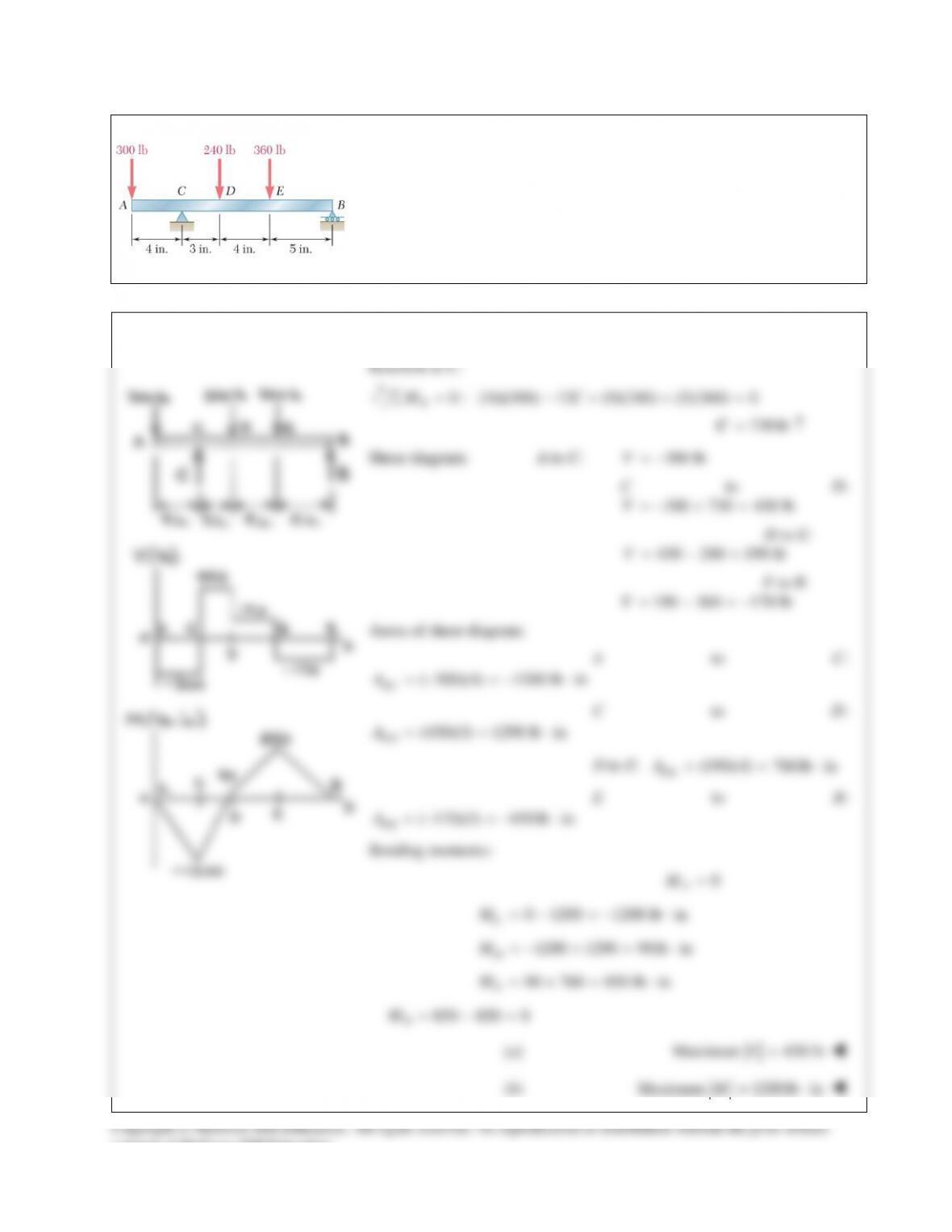
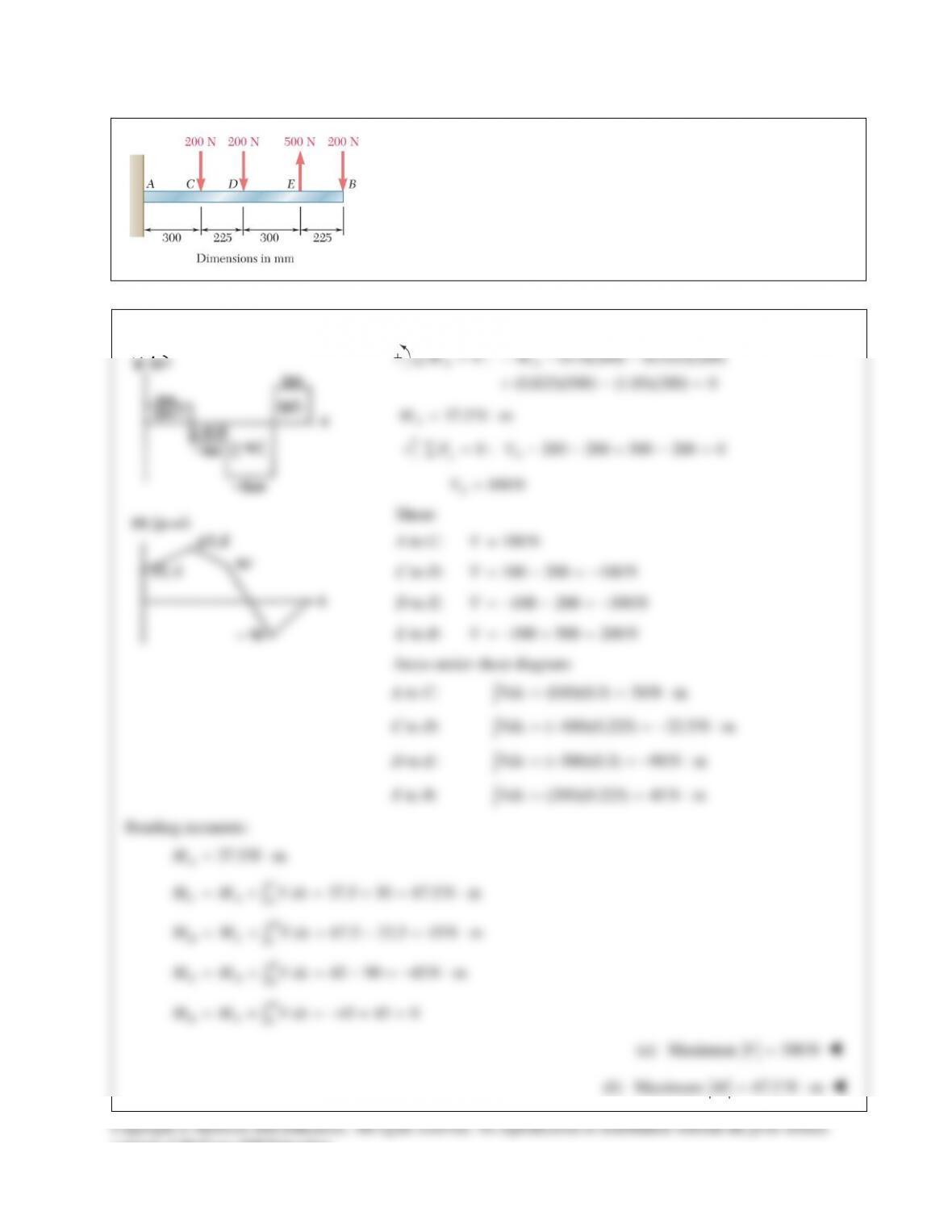
PROBLEM 12.6 Draw the shear and bending–moment diagram for the
beam and loading shown, and determine the maximum absolute value
(a) of the shear, (b) of the bending moment.
SOLUTION
0 : (0.3)(200) (0.525)(200)
(0.825)(500) (1.05)(200) 0
AA
MM∑= −− −
+ −=
37.5N m
A
M= ⋅
0 : 200 200 500 200 0
yA
FV∑= −−+−=
100N
A
V=
Shear:
A to C:
100NV=
C to D:
100 200 100 NV=−=−
D to E:
100 200 300 NV=−− =−
E to B:
300 500 200NV=−+ =
Areas under shear diagram:
A to C:
(100)(0.3) 30N mVdx = = ⋅
∫
C to D:
( 100)(0.225) 22.5N mVdx =− =−⋅
∫
D to E:
( 300)(0.3) 90 N mVdx =− =−⋅
∫
E to B:
(200)(0.225) 45N mVdx = = ⋅
∫
Bending moments:
37.5N m
A
M= ⋅
37.5 30 67.5N m
C
CA
A
M M V dx= + = += ⋅
∫
67.5 22.5 45N m
D
DC
C
M M V dx=+ =−=⋅
∫
45 90 45N m
E
ED
D
M M V dx
= + =−=− ⋅
∫
45 45 0
D
BE
E
M M V dx= + =−+ =
∫
(a) Maximum
300NV=
(b) Maximum
67.5 N mM= ⋅
consent of McGraw–Hill Education.
PROBLEM 12.35
Using the method of Sec. 12.2, Solve Prob. 12.7
PROBLEM 12.7 Draw the shear and bending–moment diagrams for the
beam and loading shown, and determine the maximum absolute value
(a) of the shear, (b) of the bending moment.
SOLUTION