PROBLEM 9.75
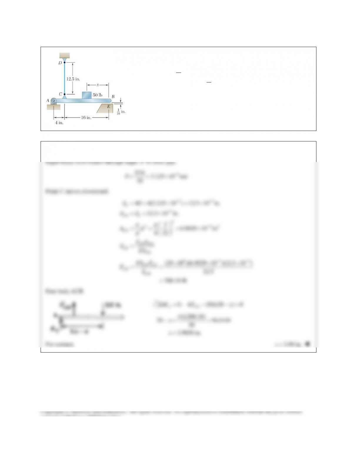
The length of the
3
32
–in.–diameter steel wire CD has been adjusted so that
with no load applied, a gap of
1
16 in.
exists between the end B of the rigid
beam ACB and a contact point E. Knowing that
6
29 10 psi,E= ×
determine where a 50–lb block should be placed on the beam in order to
cause contact between B and E.
SOLUTION
Rigid beam ACB rotates through angle
θ
to close gap.
3
1/16 3.125 10 rad
20
θ
−
= = ×
Point C moves downward.
33
3
2
2 32
4 4(3.125 10 ) 12.5 10 in.
12.5 10 in.
36.9029 10 in
4 32
C
CD C
CD
CD CD
CD CD
Ad
d
FL
EA
dθ
dd
ππ
d
−−
−
−
== ×=×
= = ×
= = = ×
=
6 33
(29 10 )(6.9029 10 )(12.5 10 )
12.5
200.18 lb
d
−−
× ××
= =
=
CD CD
CD CD
EA
FL
Free body ACB:
0: 4 (50)(20 ) 0Σ = − −=
A CD
MF x
(4)(200.18)
20 16.0144
50
3.9856 in.
x
x
−= =
=
For contact,
3.99 in.x<
consent of McGraw–Hill Education.
PROBLEM 9.76
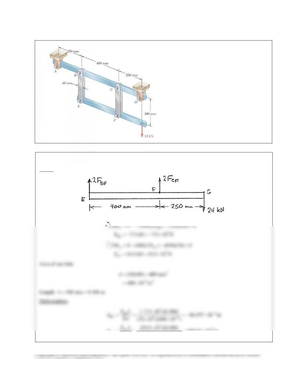
Each of the four vertical links connecting the
two rigid horizontal members is made of
aluminum
( 70 GPa)=E
and has a uniform
rectangular cross section of 10 × 40 mm. For
the loading shown, determine the deflection of
(a) point E, (b) point F, (c) point G.
SOLUTION
Statics. Free body EFG:
3
0: (400)(2 ) (250)(24) 0
7.5 kN 7.5 10 N
F BE
BE
MF
F
Σ=− − =
=− =−×
3
0: (400)(2 ) (650)(24) 0
19.5 kN 19.5 10 N
E CF
CF
MF
F
Σ= − =
= = ×
Area of one link:
2
62
(10)(40) 400 mm
400 10 m
−
= =
= ×
A
Length:
300 mm 0.300 m= =L
Deformations.
36
96
36
96
( 7.5 10 )(0.300) 80.357 10 m
(70 10 )(400 10 )
(19.5 10 )(0.300) 208.93 10 m
(70 10 )(400 10 )
BE
BE
CF
CF
FL
EA
FL
EA
δ
δ
−
−
−
−
−×
== =−×
××
×
= = = ×
××
consent of McGraw–Hill Education.
PROBLEM 9.76 (Continued)
(a) Deflection of Point E.
||
δδ
=
E BF
80.4 m
E
δm
= ↑
(b) Deflection of Point F.
F CF
δδ
=
209 m
F
δm
= ↓
Geometry change.
Let
θ
be the small change in slope angle.
66 6
80.357 10 208.93 10 723.22 10 radians
0.400
δδ
θ
−− −
+×+ ×
= = = ×
EF
EF
L
(c) Deflection of Point G.
G F FG
L
δδ θ
= +
66
6
208.93 10 (0.250)(723.22 10 )
389.73 10 m
G F FG
L
δδ θ
−−
−
=+ = ×+ ×
= ×
390 m
δm
= ↓
G
consent of McGraw–Hill Education.
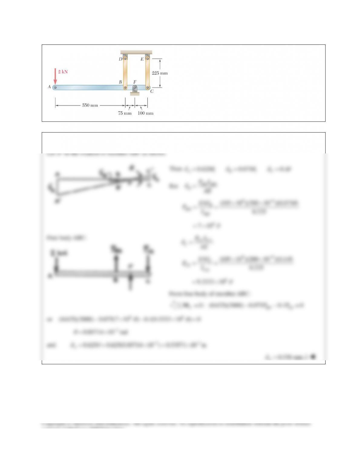
PROBLEM 9.77
Each of the rods BD and CE is made of brass (E = 105 GPa)
and has a cross–sectional area of 200 mm2. Determine the
deflection of end A of the rigid member ABC caused by
the 2-kN load.
SOLUTION
consent of McGraw-Hill Education.
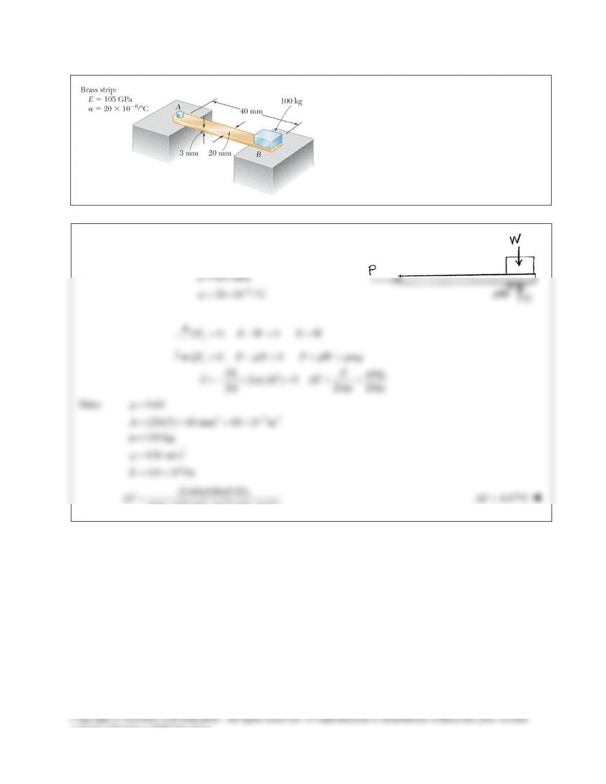
PROBLEM 9.78
The brass strip AB has been attached to a fixed
support at A and rests on a rough support at B.
Knowing that the coefficient of friction is 0.60
between the strip and the support at B, determine
the decrease in temperature for which slipping will
impend.
SOLUTION
Brass strip:
(105 10 )(60 10 )(20 10 )
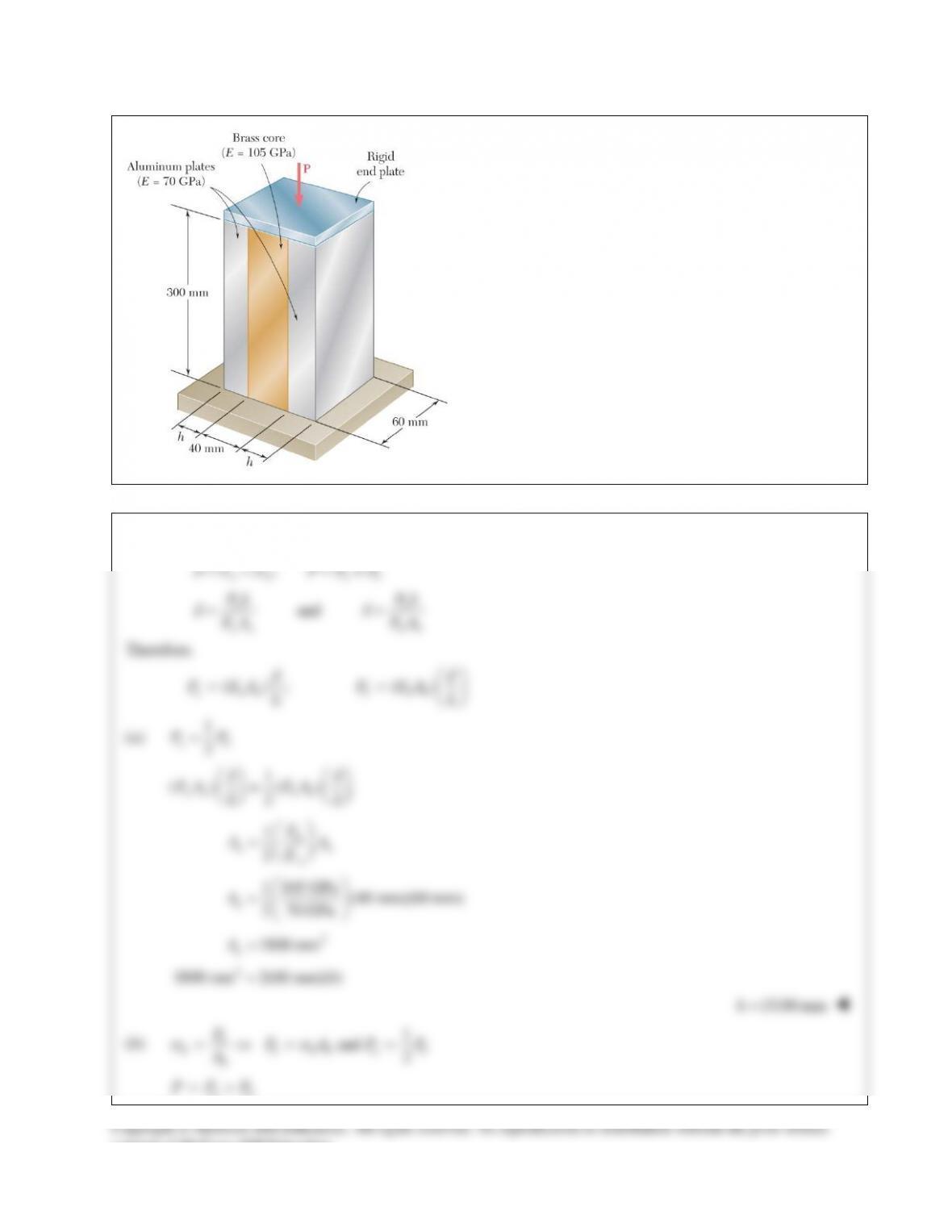
PROBLEM 9.79
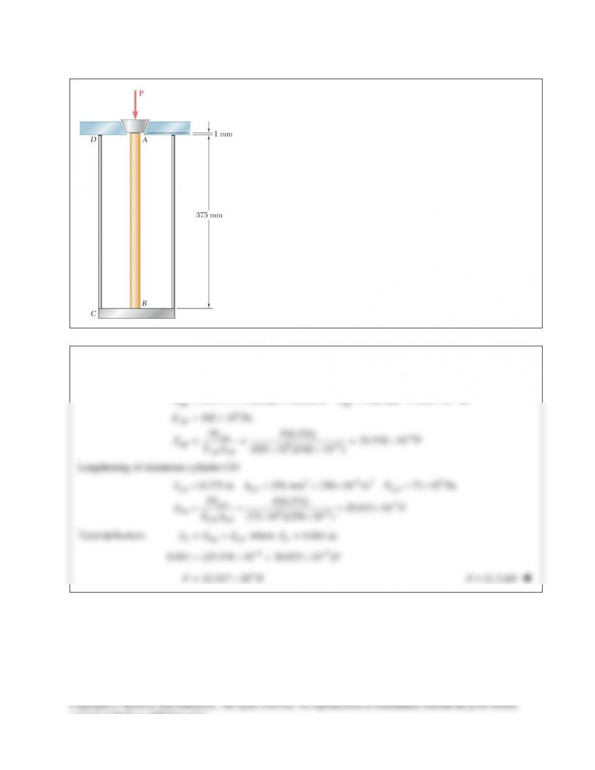
An axial centric force P is applied to the composite block
shown by means of a rigid end plate. Determine (a) the
value of h if the portion of the load carried by the
aluminum plates is half the portion of the load carried by
the brass core, (b) the total load if the stress in the brass is
80 MPa.
SOLUTION
;
a b ab
PP P
δδ δ
= = = +
and
ab
aa bb
PL PL
EA EA
δδ
= =
Therefore,
( ); ( )
a aa b bb
P EA P EA
LL
δδ
= =
(a)
1
2
ab
PP=
1
() ()
2
aa bb
EA EA
LL
δδ
=
1
2
b
ab
a
E
AA
E
=
1 105 GPa
(40 mm)(60 mm)
2 70 GPa
=
a
A
2
1800 mm
a
A=
2
1800 mm 2(60 mm)( )=h
15.00 mmh=
(b)
1
and 2
=⇒= =
b
b b bb a b
b
PP AP P
A
σσ
ab
PPP= +
consent of McGraw–Hill Education.
PROBLEM 9.75
The length of the
3
32
–in.–diameter steel wire CD has been adjusted so that
with no load applied, a gap of
1
16 in.
exists between the end B of the rigid
beam ACB and a contact point E. Knowing that
6
29 10 psi,E= ×
determine where a 50–lb block should be placed on the beam in order to
cause contact between B and E.
SOLUTION
Rigid beam ACB rotates through angle
θ
to close gap.
3
1/16 3.125 10 rad
20
θ
−
= = ×
Point C moves downward.
33
3
2
2 32
4 4(3.125 10 ) 12.5 10 in.
12.5 10 in.
36.9029 10 in
4 32
C
CD C
CD
CD CD
CD CD
Ad
d
FL
EA
dθ
dd
ππ
d
−−
−
−
== ×=×
= = ×
= = = ×
=
6 33
(29 10 )(6.9029 10 )(12.5 10 )
12.5
200.18 lb
d
−−
× ××
= =
=
CD CD
CD CD
EA
FL
Free body ACB:
0: 4 (50)(20 ) 0Σ = − −=
A CD
MF x
(4)(200.18)
20 16.0144
50
3.9856 in.
x
x
−= =
=
For contact,
3.99 in.x<
consent of McGraw–Hill Education.
PROBLEM 9.76
Each of the four vertical links connecting the
two rigid horizontal members is made of
aluminum
( 70 GPa)=E
and has a uniform
rectangular cross section of 10 × 40 mm. For
the loading shown, determine the deflection of
(a) point E, (b) point F, (c) point G.
SOLUTION
Statics. Free body EFG:
3
0: (400)(2 ) (250)(24) 0
7.5 kN 7.5 10 N
F BE
BE
MF
F
Σ=− − =
=− =−×
3
0: (400)(2 ) (650)(24) 0
19.5 kN 19.5 10 N
E CF
CF
MF
F
Σ= − =
= = ×
Area of one link:
2
62
(10)(40) 400 mm
400 10 m
−
= =
= ×
A
Length:
300 mm 0.300 m= =L
Deformations.
36
96
36
96
( 7.5 10 )(0.300) 80.357 10 m
(70 10 )(400 10 )
(19.5 10 )(0.300) 208.93 10 m
(70 10 )(400 10 )
BE
BE
CF
CF
FL
EA
FL
EA
δ
δ
−
−
−
−
−×
== =−×
××
×
= = = ×
××
consent of McGraw–Hill Education.
PROBLEM 9.76 (Continued)
(a) Deflection of Point E.
||
δδ
=
E BF
80.4 m
E
δm
= ↑
(b) Deflection of Point F.
F CF
δδ
=
209 m
F
δm
= ↓
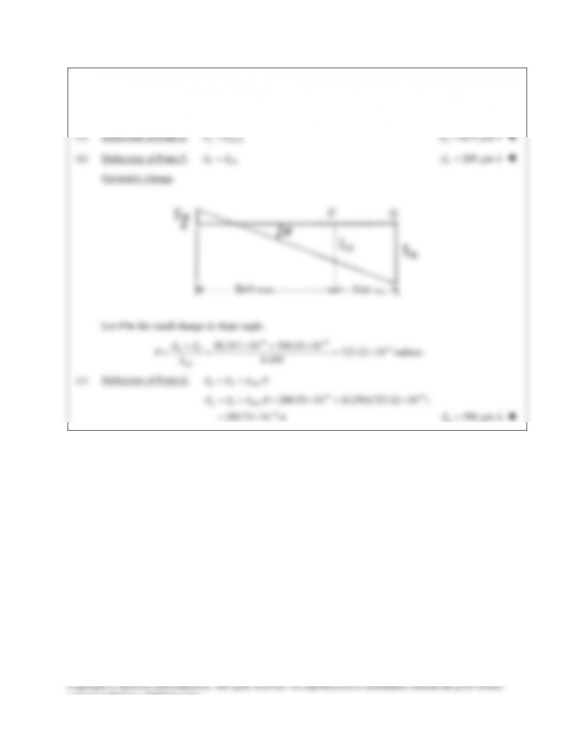
Geometry change.
Let
θ
be the small change in slope angle.
66 6
80.357 10 208.93 10 723.22 10 radians
0.400
δδ
θ
−− −
+×+ ×
= = = ×
EF
EF
L
(c) Deflection of Point G.
G F FG
L
δδ θ
= +
66
6
208.93 10 (0.250)(723.22 10 )
389.73 10 m
G F FG
L
δδ θ
−−
−
=+ = ×+ ×
= ×
390 m
δm
= ↓
G
consent of McGraw–Hill Education.
PROBLEM 9.77
Each of the rods BD and CE is made of brass (E = 105 GPa)
and has a cross–sectional area of 200 mm2. Determine the
deflection of end A of the rigid member ABC caused by
the 2-kN load.
SOLUTION
consent of McGraw-Hill Education.
PROBLEM 9.78
The brass strip AB has been attached to a fixed
support at A and rests on a rough support at B.
Knowing that the coefficient of friction is 0.60
between the strip and the support at B, determine
the decrease in temperature for which slipping will
impend.
SOLUTION
Brass strip:
(105 10 )(60 10 )(20 10 )
PROBLEM 9.79
An axial centric force P is applied to the composite block
shown by means of a rigid end plate. Determine (a) the
value of h if the portion of the load carried by the
aluminum plates is half the portion of the load carried by
the brass core, (b) the total load if the stress in the brass is
80 MPa.
SOLUTION
;
a b ab
PP P
δδ δ
= = = +
and
ab
aa bb
PL PL
EA EA
δδ
= =
Therefore,
( ); ( )
a aa b bb
P EA P EA
LL
δδ
= =
(a)
1
2
ab
PP=
1
() ()
2
aa bb
EA EA
LL
δδ
=
1
2
b
ab
a
E
AA
E
=
1 105 GPa
(40 mm)(60 mm)
2 70 GPa
=
a
A
2
1800 mm
a
A=
2
1800 mm 2(60 mm)( )=h
15.00 mmh=
(b)
1
and 2
=⇒= =
b
b b bb a b
b
PP AP P
A
σσ
ab
PPP= +
consent of McGraw–Hill Education.