PROBLEM 12.77
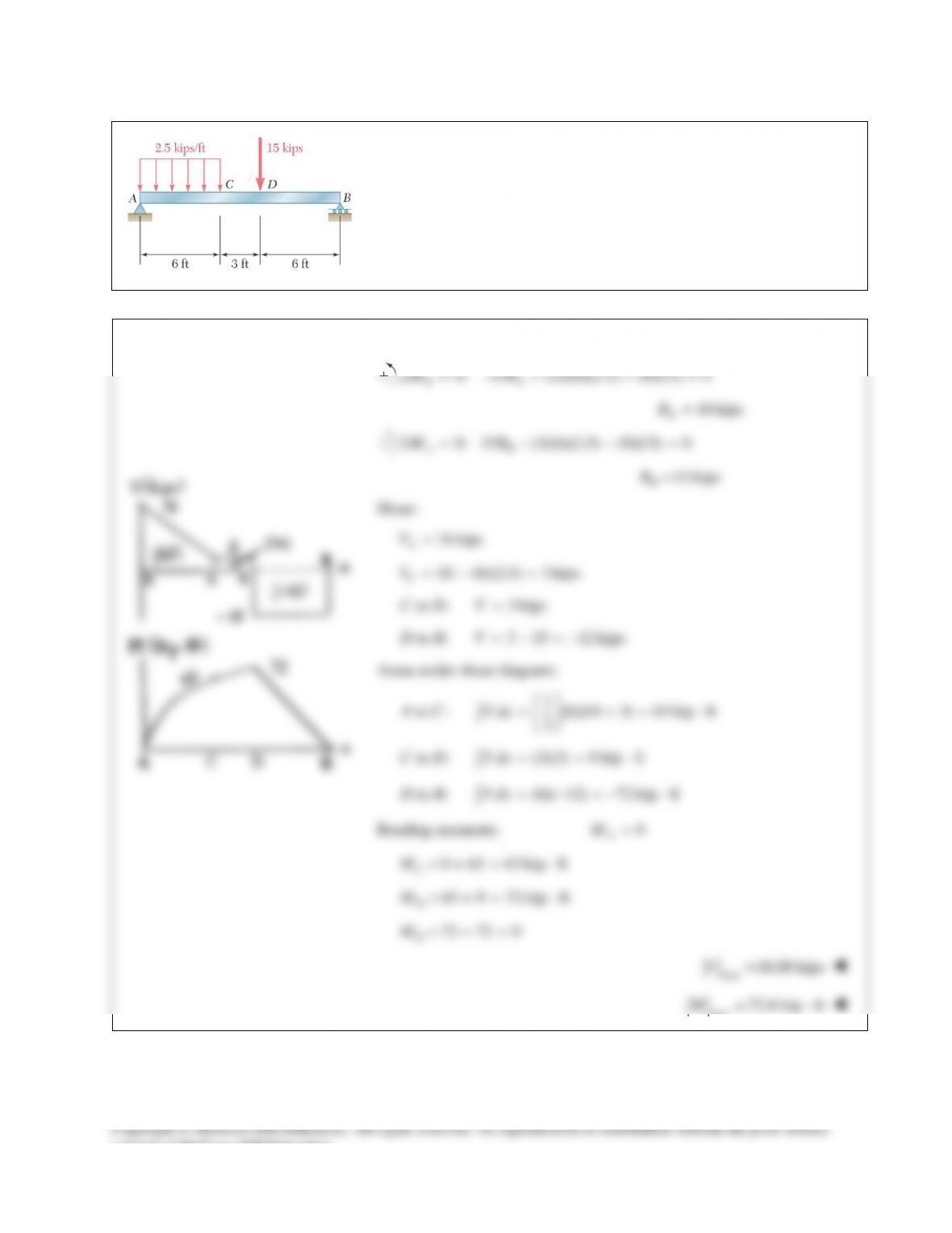
Draw the shear and bending–moment diagrams for the beam and loading
shown, and determine the maximum absolute value (a) of the shear,
(b) of the bending moment.
SOLUTION
0: 15 (12)(6)(2.5) (6)(15) 0
BA
MRΣ= − + + =
18 kips
A
R=
0: 15 (3)(6)(2.5) (9)(15) 0
AB
MRΣ= − − =
12 kips
B
R=
Shear:
18 kips
A
V=
18 (6)(2.5) 3 kips
C
V=−=
to : 3 kipsCD V=
to : 3 15 12 kipsDB V=−=−
Areas under shear diagram:
1
to : (6)(18 3) 63 kip ft
2
A C V dx
= += ⋅
∫
to : (3)(3) 9 kip ft
C D V dx = = ⋅
∫
to : (6)( 12) 72 kip ftD B V dx = −=− ⋅
∫
Bending moments:
0
A
M=
0 63 63 kip ft
C
M=+= ⋅
63 9 72 kip ft
D
M= += ⋅
72 72 0
B
M=−=
max
18.00 kipsV=
max
72.0 kip ftM= ⋅
consent of McGraw–Hill Education.
PROBLEM 12.78
Draw the shear and bending–moment diagrams for the beam and loading
shown, and determine the maximum absolute value (a) of the shear, (b) of
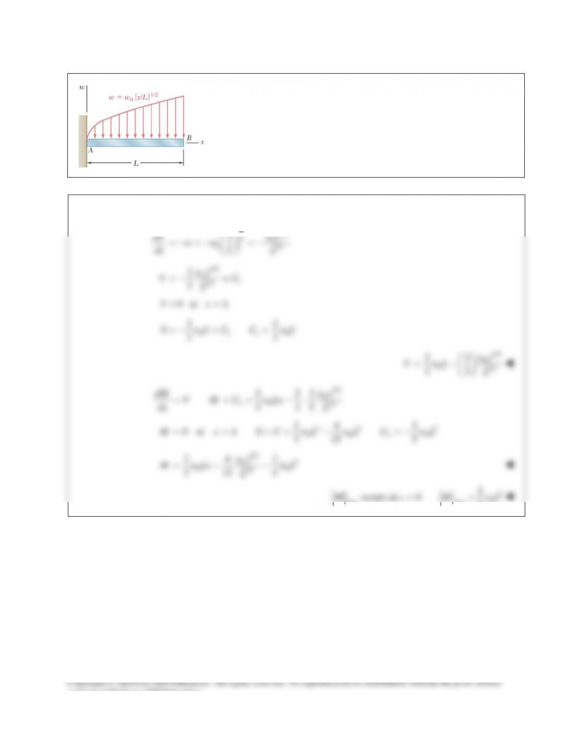
PROBLEM 12.79
Determine (a) the equations of the shear and bending–moment curves for
the beam and loading shown, (b) the maximum absolute value of the
bending moment in the beam.
SOLUTION
11/2
20
01/2
dV x w x
ww
dx L L
=−=− =−
3/2
1
1/2
2
3o
wx
VC
L
=−+
0 atV xL= =
01 1 0
22
033
wL C C wL=−+ =
3/2
0
01/2
22
33
wx
V wL L
= −
5/2
0
20 1/2
2 22
3 35
dM w x
V M C w Lx
dx L
= = + −⋅
22 2
0 020
24 2
0 at 0 3 15 5
M x L C wL wL C wL= = =+− =−
5/2 2
0
00
1/2
24 2
3 15 5
wx
M wLx wL
L
=−−
2
0
max max
2
occurs at 0 5
M x M wL= =
consent of McGraw–Hill Education.
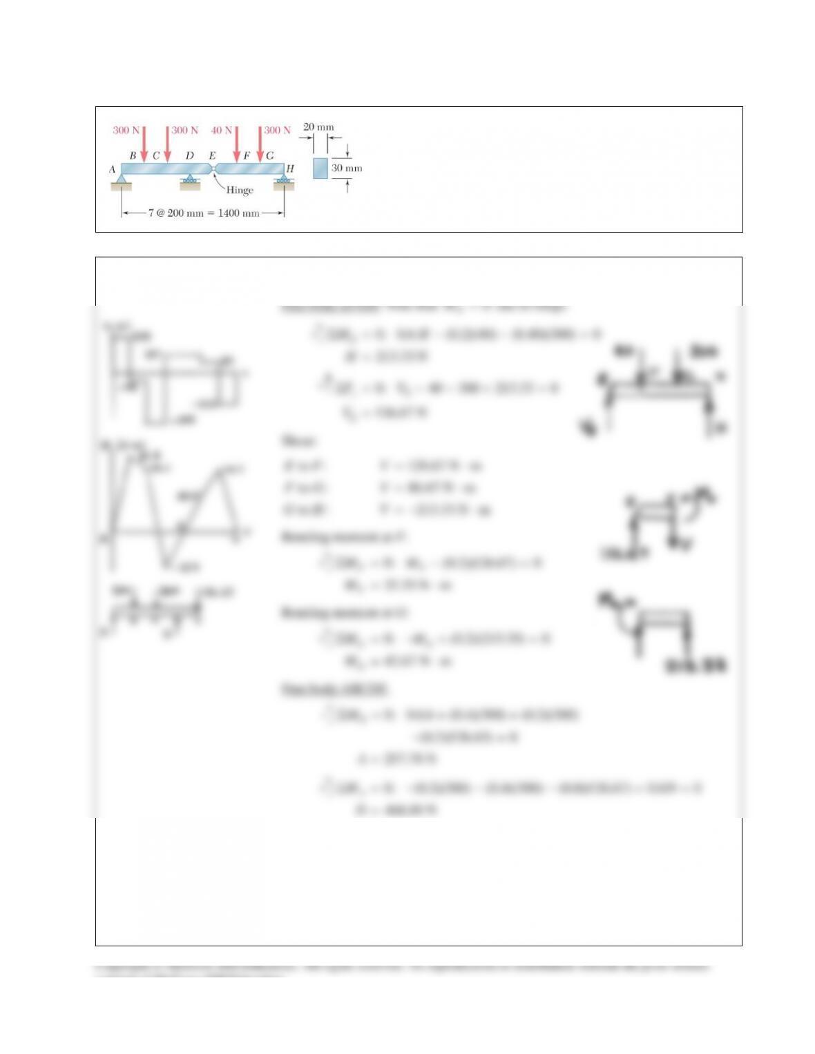
PROBLEM 12.80
Draw the shear and bending–moment diagrams for the beam
and loading shown, and determine the maximum normal stress
due to bending.
SOLUTION
PROBLEM 12.80 (Continued)
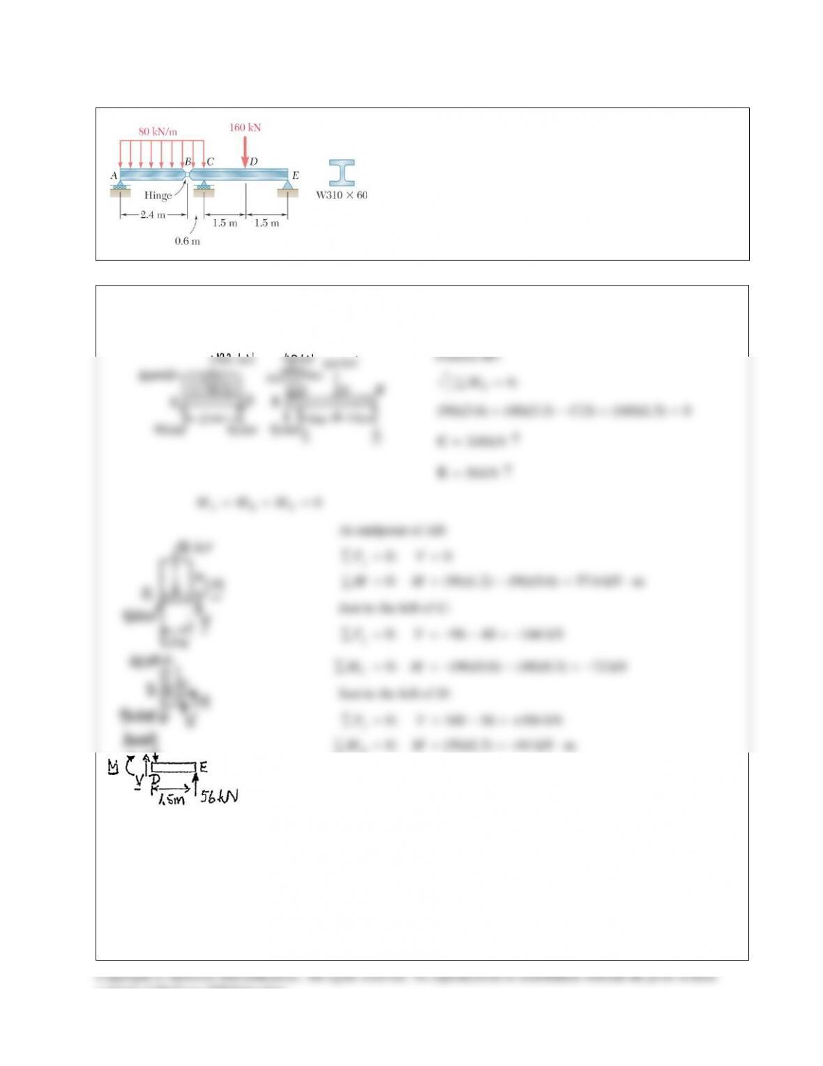
PROBLEM 12.81
Draw the shear and bending–moment diagrams for the beam
and loading shown and determine the maximum normal
stress due to bending.
SOLUTION
Statics: Consider portion AB and BE separately.
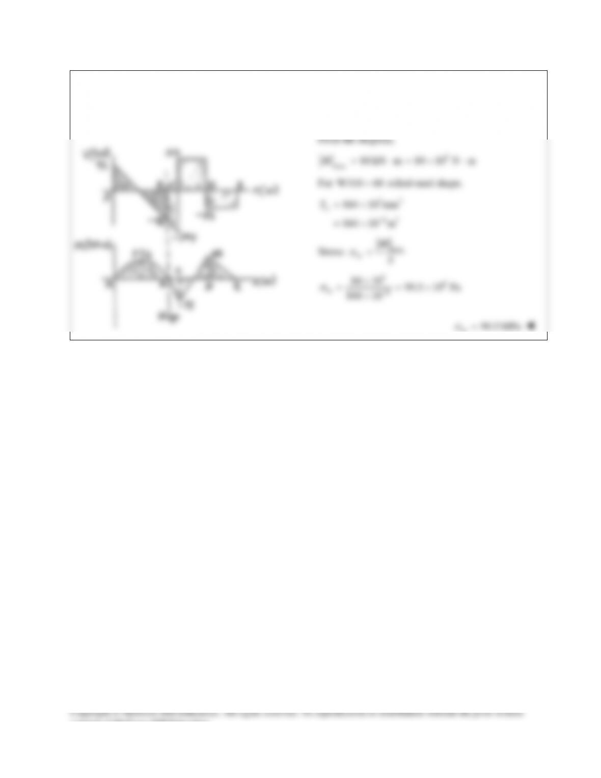
PROBLEM 12.81 (Continued)
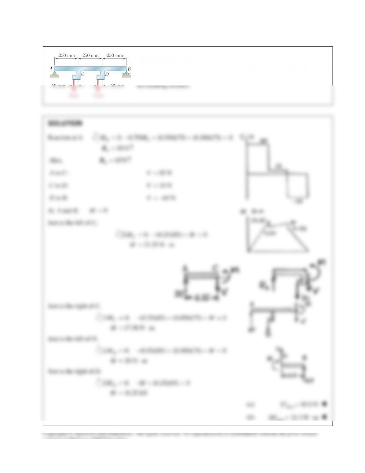
PROBLEM 12.82
Determine (a) the distance a for which the maximum absolute
value of the bending moment in the beam is as small as
possible, (b) the corresponding maximum normal stress due to
bending. (Hint: Draw the bending–moment diagram and equate
the absolute values of the largest positive and negative bending
moments obtained.)
SOLUTION
Reaction at B:
0: 5 (8)(10) 13 0
1(80 5 )
18
CB
B
Ma R
Ra
Σ= − + =
= −
Bending moment at D:
0: 5 0
5
5 (80 5 )
13
D DB
DB
M MR
MR a
Σ = −+ =
= = −
Bending moment at C:
05 0
5
CC
C
M aM
Ma
= +=
= −
Equate:
5
5 (80 5 )
13
CD
MM
aa
−=
= −
4.4444 fta=
( ) 4.44 ftaa=
Then
(5)(4.4444) 22.222 kip ft
CD
MM−= = = ⋅
max
| | 22.222 kip ft 266.67 kip in.M= ⋅= ⋅
For
W14 22
×
rolled–steel section,
3
29.0 in
S=
Normal stress:
266.67 9.20 ksi
29.0
M
S
s
= = =
( ) 9.20 ksib
consent of McGraw–Hill Education.
PROBLEM 12.83
Beam AB, of length L and square cross section of side a, is
supported by a pivot at C and loaded as shown. (a) Check that the
beam is in equilibrium. (b) Show that the maximum normal stress
due to bending occurs at C and is equal to
23
0
/(1.5 ) .wL a
SOLUTION
PROBLEM 12.77
Draw the shear and bending–moment diagrams for the beam and loading
shown, and determine the maximum absolute value (a) of the shear,
(b) of the bending moment.
SOLUTION
0: 15 (12)(6)(2.5) (6)(15) 0
BA
MRΣ= − + + =
18 kips
A
R=
0: 15 (3)(6)(2.5) (9)(15) 0
AB
MRΣ= − − =
12 kips
B
R=
Shear:
18 kips
A
V=
18 (6)(2.5) 3 kips
C
V=−=
to : 3 kipsCD V=
to : 3 15 12 kipsDB V=−=−
Areas under shear diagram:
1
to : (6)(18 3) 63 kip ft
2
A C V dx
= += ⋅
∫
to : (3)(3) 9 kip ft
C D V dx = = ⋅
∫
to : (6)( 12) 72 kip ftD B V dx = −=− ⋅
∫
Bending moments:
0
A
M=
0 63 63 kip ft
C
M=+= ⋅
63 9 72 kip ft
D
M= += ⋅
72 72 0
B
M=−=
max
18.00 kipsV=
max
72.0 kip ftM= ⋅
consent of McGraw–Hill Education.
PROBLEM 12.78
Draw the shear and bending–moment diagrams for the beam and loading
shown, and determine the maximum absolute value (a) of the shear, (b) of
PROBLEM 12.79
Determine (a) the equations of the shear and bending–moment curves for
the beam and loading shown, (b) the maximum absolute value of the
bending moment in the beam.
SOLUTION
11/2
20
01/2
dV x w x
ww
dx L L
=−=− =−
3/2
1
1/2
2
3o
wx
VC
L
=−+
0 atV xL= =
01 1 0
22
033
wL C C wL=−+ =
3/2
0
01/2
22
33
wx
V wL L
= −
5/2
0
20 1/2
2 22
3 35
dM w x
V M C w Lx
dx L
= = + −⋅
22 2
0 020
24 2
0 at 0 3 15 5
M x L C wL wL C wL= = =+− =−
5/2 2
0
00
1/2
24 2
3 15 5
wx
M wLx wL
L
=−−
2
0
max max
2
occurs at 0 5
M x M wL= =
consent of McGraw–Hill Education.
PROBLEM 12.80
Draw the shear and bending–moment diagrams for the beam
and loading shown, and determine the maximum normal stress
due to bending.
SOLUTION
PROBLEM 12.80 (Continued)
PROBLEM 12.81
Draw the shear and bending–moment diagrams for the beam
and loading shown and determine the maximum normal
stress due to bending.
SOLUTION
Statics: Consider portion AB and BE separately.
PROBLEM 12.81 (Continued)
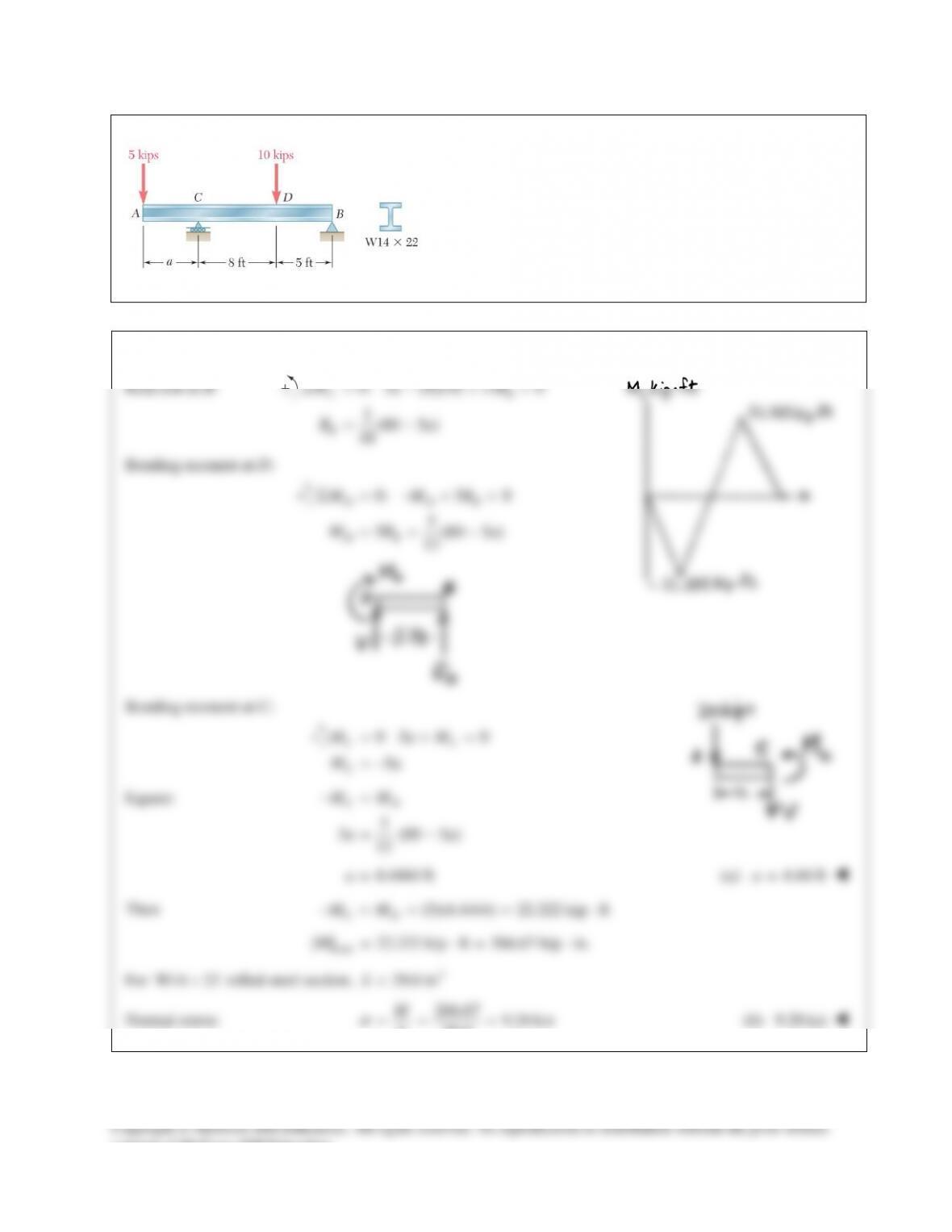
PROBLEM 12.82
Determine (a) the distance a for which the maximum absolute
value of the bending moment in the beam is as small as
possible, (b) the corresponding maximum normal stress due to
bending. (Hint: Draw the bending–moment diagram and equate
the absolute values of the largest positive and negative bending
moments obtained.)
SOLUTION
Reaction at B:
0: 5 (8)(10) 13 0
1(80 5 )
18
CB
B
Ma R
Ra
Σ= − + =
= −
Bending moment at D:
0: 5 0
5
5 (80 5 )
13
D DB
DB
M MR
MR a
Σ = −+ =
= = −
Bending moment at C:
05 0
5
CC
C
M aM
Ma
= +=
= −
Equate:
5
5 (80 5 )
13
CD
MM
aa
−=
= −
4.4444 fta=
( ) 4.44 ftaa=
Then
(5)(4.4444) 22.222 kip ft
CD
MM−= = = ⋅
max
| | 22.222 kip ft 266.67 kip in.M= ⋅= ⋅
For
W14 22
×
rolled–steel section,
3
29.0 in
S=
Normal stress:
266.67 9.20 ksi
29.0
M
S
s
= = =
( ) 9.20 ksib
consent of McGraw–Hill Education.
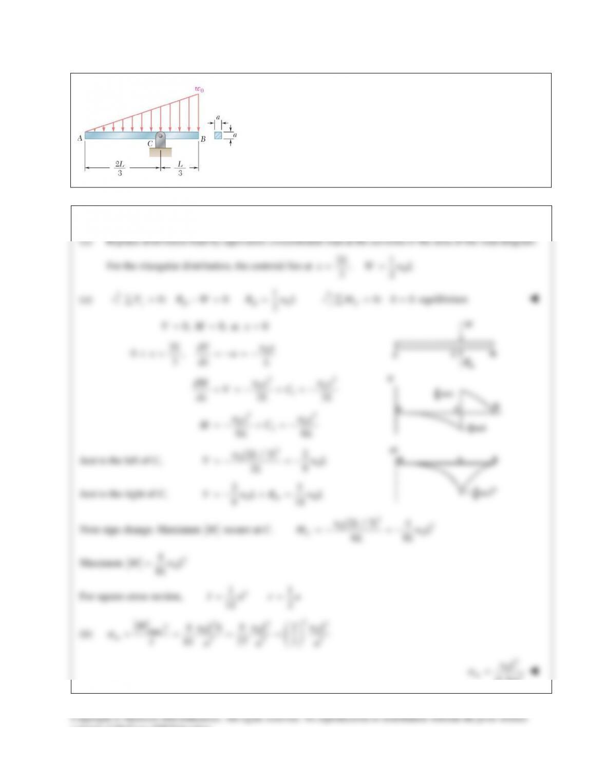
PROBLEM 12.83
Beam AB, of length L and square cross section of side a, is
supported by a pivot at C and loaded as shown. (a) Check that the
beam is in equilibrium. (b) Show that the maximum normal stress
due to bending occurs at C and is equal to
23
0
/(1.5 ) .wL a
SOLUTION