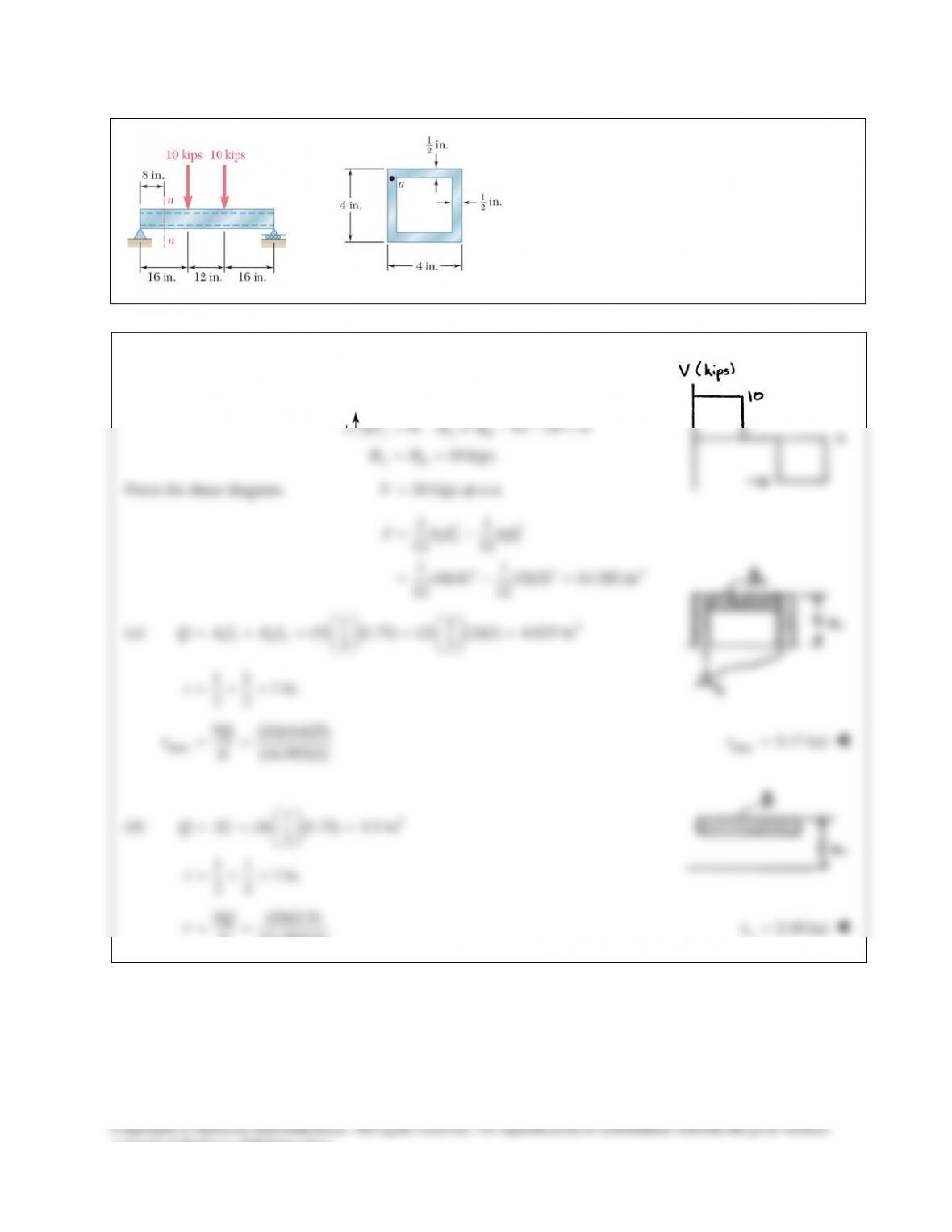
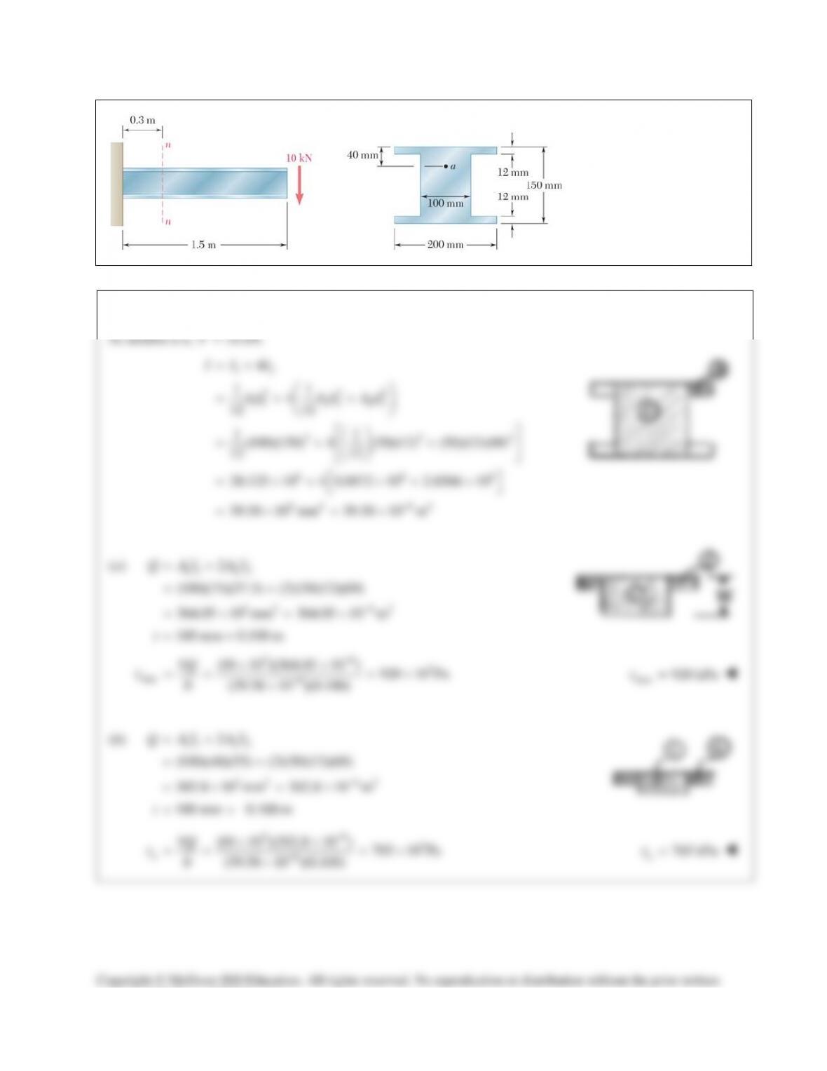
PROBLEM 13.11
For the beam and loading
shown, consider section
n-n and determine (a) the
largest shearing stress in
that section, (b
) the
shearing stress at point a.
SOLUTION
At section n–n,
10 kN.V=
12
3 32
11 2 2 2 2
3 32
6 66
6 4 64
4
11
4
12 12
11
(100)(150) 4 (50)(12) (50)(12)(69)
12 12
28.125 10 4 0.0072 10 2.8566 10
39.58 10 mm 39.58 10 m
II I
bh bh Ad
−
= +
=++
=++
= ×+ ×+ ×
=×=×
(a)
11 2 2
3 3 63
2
(100)(75)(37.5) (2)(50)(12)(69)
364.05 10 mm 364.05 10 m
100 mm = 0.100 m
Q Ay Ay
t
−
= +
= +
=×=×
=
36
3
max 6
(10 10 )(364.05 10 ) 920 10 Pa
(39.58 10 )(0.100)
VQ
It
t
−
−
××
= = = ×
×
max
920 kPa
t
=
(b)
11 2 2
3 3 63
2
(100)(40)(55) (2)(50)(12)(69)
302.8 10 mm 302.8 10 m
100 mm 0.100 m
Q Ay Ay
t
−
= +
= +
=×=×
= =
363
6
(10 10 )(302.8 10 ) 765 10 Pa
(39.58 10 )(0.100)
a
VQ
It
t
−
−
××
= = = ×
×
765 kPa
a
t
=
Copyright © McGraw–Hill Education. All rights reserved. No reproduction or distribution without the prior written
consent of McGraw–Hill Education.
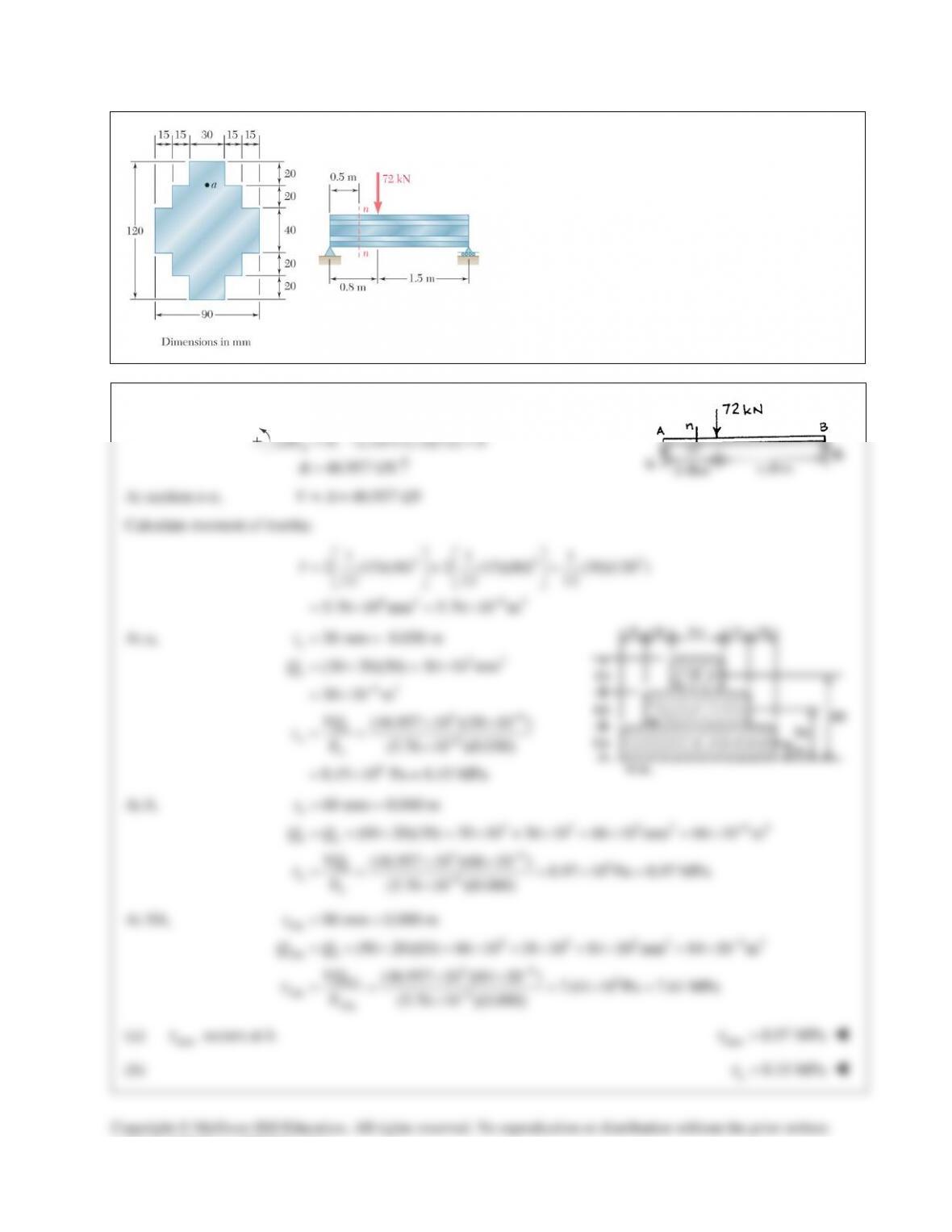
PROBLEM 13.12
For the beam and loading shown, consider
section n-n and determine (a) the largest shearing
stress in that section, (b) the shearing stress at
point a.
SOLUTION
0: 2.3 (1.5)(72) 0
46.957 kN
B
MA
Σ=− + =
= ↑A
At section n-n,
46.957 kNVA
= =
Calculate moment of inertia:
3 33
6 4 64
1 11
2 (15)(40) 2 (15)(80) (30)(120 )
12 12 12
5.76 10 mm 5.76 10 m
I
−
=++
=×=×
At a,
33
63
36
6
6
30 mm 0.030 m
(30 20)(50) 30 10 mm
30 10 m
(46.957 10 )(30 10 )
(5.76 10 )(0.030)
8.15 10 Pa = 8.15 MPa
a
a
a
aa
t
Q
VQ
It
t
−
−
−
= =
=×=×
= ×
××
= = ×
= ×
At b,
3 3 3 3 64
36 6
6
60 mm 0.060 m
(60 20)(30) 30 10 36 10 66 10 mm 66 10 m
(46.957 10 )(66 10 ) 8.97 10 Pa 8.97 MPa
(5.76 10 )(0.060)
b
ba
b
bb
t
QQ
VQ
It
t
−
−
−
= =
= + × =× +× =× =×
××
== =×=
×
At NA,
NA
3 3 3 3 63
NA
36 6
NA
NA 6
NA
90 mm 0.090 m
(90 20)(10) 66 10 18 10 84 10 mm 84 10 m
(46.957 10 )(84 10 ) 7.61 10 Pa 7.61 MPa
(5.76 10 )(0.090)
b
t
QQ
VQ
It
t
−
−
−
= =
= + × =× +× =× =×
××
= = =×=
×
(a)
max
t
occurs at b.
max 8.97 MPa
t
=
(b)
8.15 MPa
a
t
=
Copyright © McGraw–Hill Education. All rights reserved. No reproduction or distribution without the prior written
consent of McGraw–Hill Education.
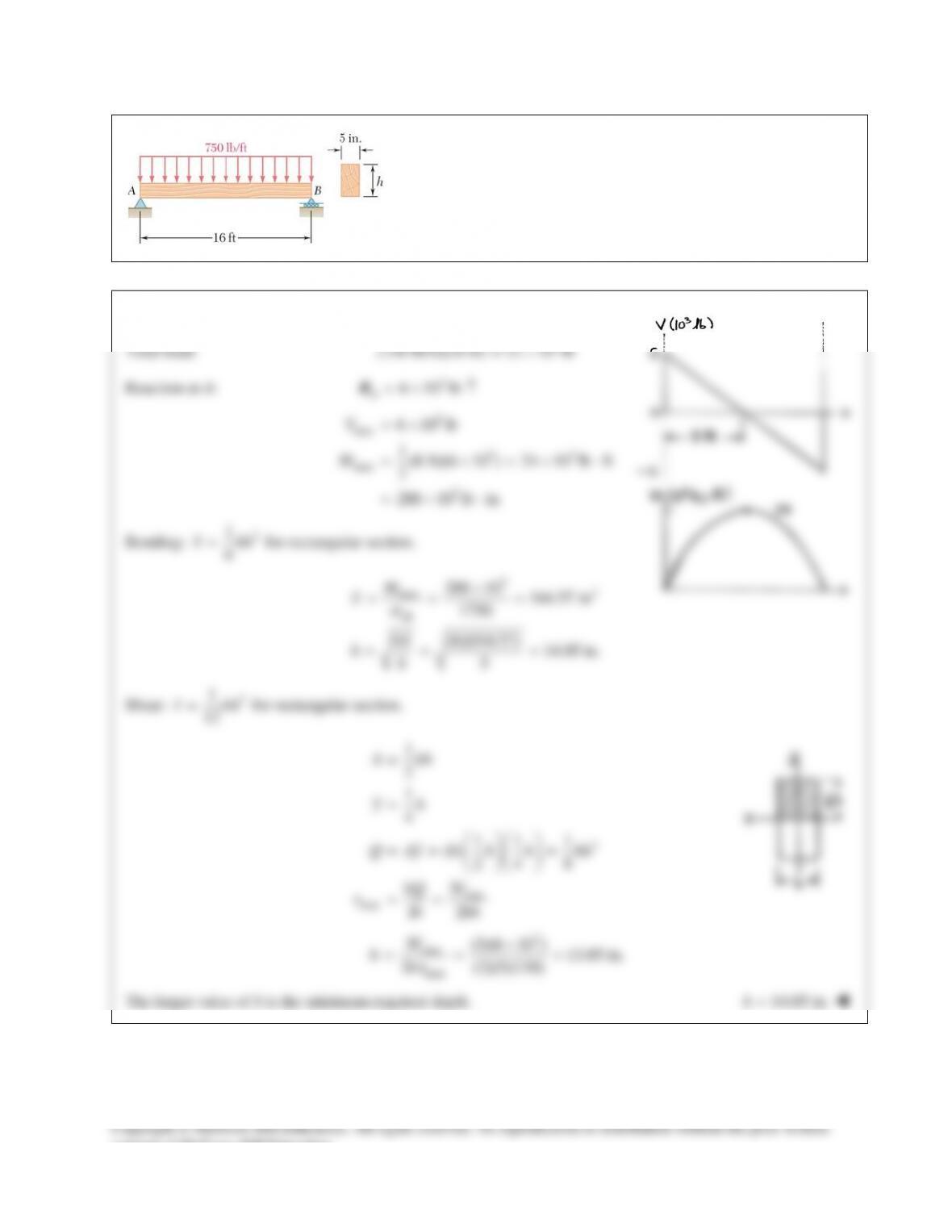
PROBLEM 13.13
For the beam and loading shown, determine the minimum required
depth h, knowing that for the grade of timber used,
all 1750 psi
s
=
and
all
130 psi.
τ
=
SOLUTION
Total load:
3
(750 lb/ft)(16 ft) 12 10 lb= ×
Reaction at A:
3
6 10 lb
A
=×↑R
3
max
33
max
3
6 10 lb
1(8 ft)(6 10 ) 24 10 lb ft
2
288 10 lb in
V
M
= ×
= ×=× ⋅
=×⋅
Bending:
2
1
6
S bh=
for rectangular section.
33
max
all
288 10 164.57 in
1750
6 (6)(164.57) 14.05 in.
5
M
S
S
hb
s
×
= = =
= = =
Shear:
3
1
12
I bh=
for rectangular section.
2
max
max
1
2
1
4
11 1
() 24 8
3
2
A bh
yh
Q Ay b h h bh
VQ V
Ib bh
τ
=
=
= = =
= =
3
max
max
3 (3)(6 10 ) 13.85 in.
2 (2)(5)(130)
V
hb
τ
×
= = =
The larger value of h is the minimum required depth.
14.05 in.h=
consent of McGraw–Hill Education.
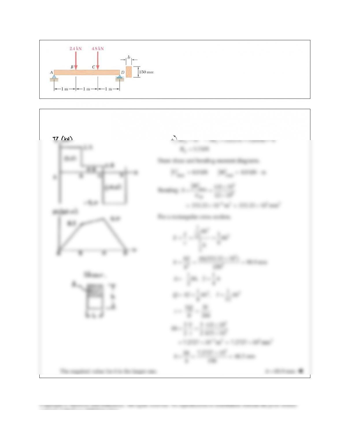
PROBLEM 13.14
For the beam and loading shown, determine the minimum
required width b, knowing that for the grade of timber
used,
all
12 MPa
σ
=
and
all
825 kPa.
τ
=
SOLUTION
0: 3 (2)(2.4) (1)(4.8) 0
3.2 kN
DA
A
MR
R
=−+ + =
=
Draw shear and bending moment diagrams.
max max
4.0 kN 4.0 kN mVM= = ⋅
Bending:
3
max 6
all
63 3 3
4.0 10
12 10
333.33 10 m 333.33 10 mm
M
S
σ
−
×
= = ×
=×=×
For a rectangular cross section,
3
2
3
22
23
3
3
32 3 2
3
11
12
16
2
6 (6)(333.33 10 ) 88.9 mm
150
11
,
24
11
,
8 12
3
2
3 3 4.0 10
22
825 10
7.2727 10 m 7.2727 10 mm
7.2727 10 48.5 mm
150
bh
I
S bh
ch
S
bh
A bh y h
Q Ay bh I bh
VQ V
It bh
V
bh
bh
bh
τ
τ
−
= = =
×
= = =
= =
= = =
= =
×
= = ×
=×=×
×
= = =
The required value for b is the larger one.
88.9 mmb=
consent of McGraw–Hill Education.
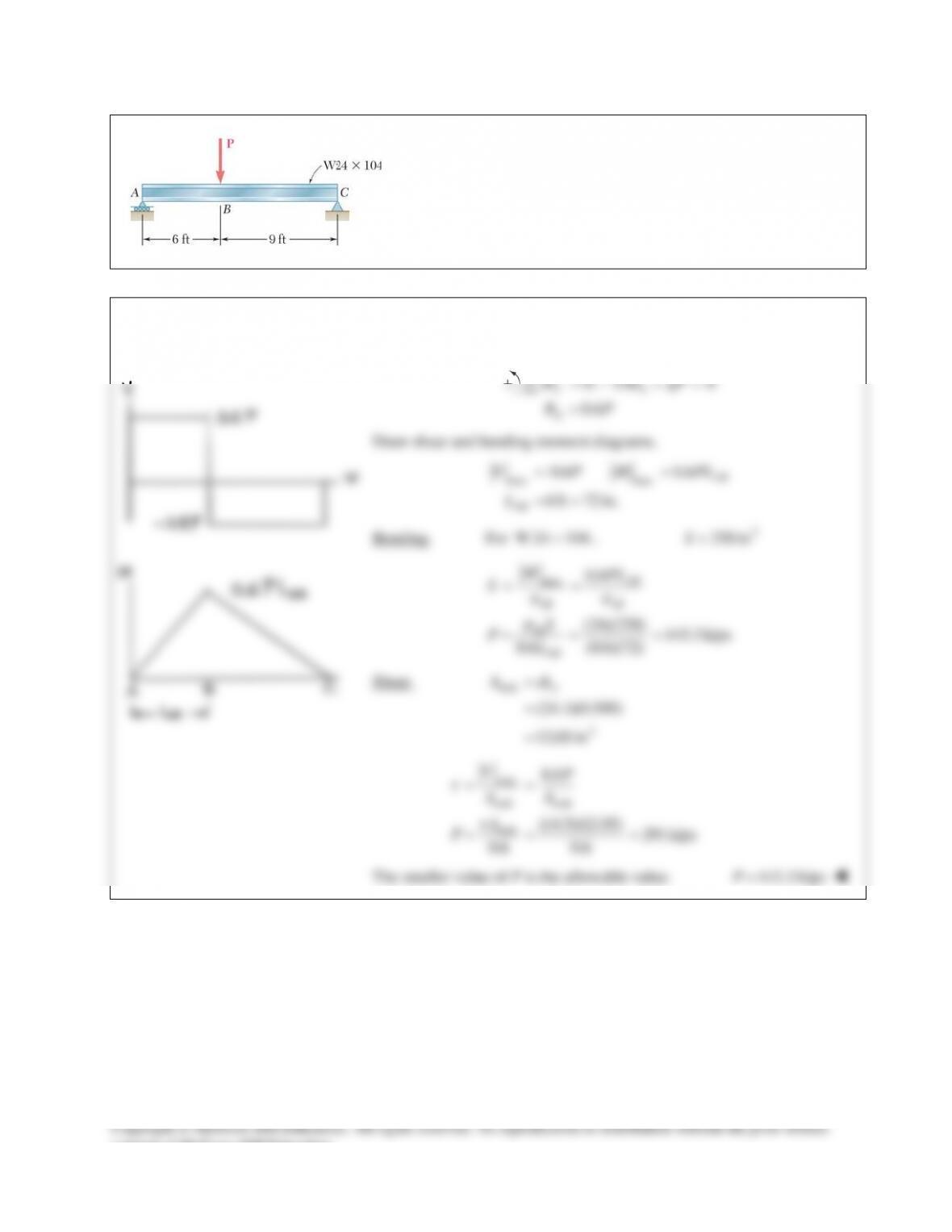
PROBLEM 13.15
For the wide–flange beam with the loading shown, determine the
largest load P that can be applied, knowing that the maximum
normal stress is 24 ksi and the largest shearing stress using the
approximation
web
/
m
VA
τ
=
is 14.5 ksi.
SOLUTION
0: 15 0
0.6
CA
A
M R qP
RP
=− +=
=
∑
Draw shear and bending moment diagrams.
max max
0.6 0.6
6ft 72 in.
AB
AB
V P M PL
L
= =
= =
Bending. For
W24 104×
,
3
258 inS=
max
all all
all
0.6
(24)(258) 143.3 kips
0.6 (0.6)(72)
AB
AB
MPL
S
S
PL
ss
s
= =
= = =
Shear.
web
2
(24.1)(0.500)
12.05 in
w
A dt
=
=
=
max
web web
web
0.6
(14.5)(12.05) 291kips
0.6 0.6
VP
AA
A
P
τ
τ
= =
= = =
The smaller value of P is the allowable value.
143.3 kipsP=
consent of McGraw–Hill Education.
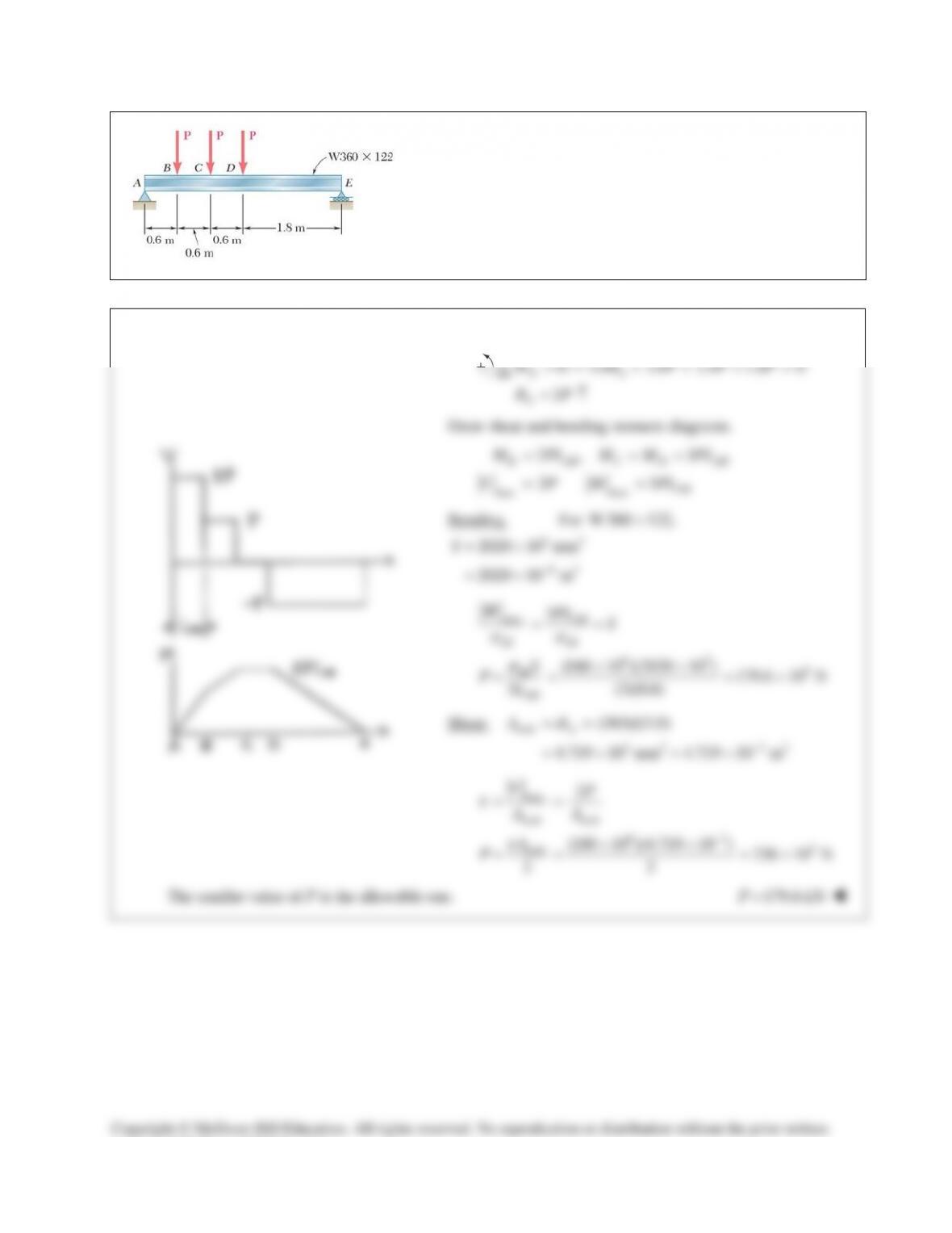
PROBLEM 13.16
For the wide–flange beam with the loading shown, determine the
largest load P that can be applied, knowing that the maximum
normal stress is 160 MPa and the largest shearing stress using the
approximation
web
/
m
VA
τ
=
is 100 MPa.
SOLUTION
0: 3.6 3.0 2.4 1.8 0
2
EA
A
M R PPP
RP
=− +++=
= ↑
∑
Draw shear and bending moment diagrams.
max max
2, 3
23
B AB C D AB
AB
M PL M M PL
V P M PL
= = =
= =
Bending. For
W360 122,
×
33
63
= 2020 10 mm
= 2020 10 m
S
−
×
×
max
all all
63 3
all
3
(160 10 )(2020 10 ) 179.6 10 N
3 (3)(0.6)
AB
AB
MPL S
S
PL
σσ
σ
= =
××
= = = ×
Shear.
web
3 2 32
(363)(13.0)
4.719 10 mm 4.719 10 m
w
A dt
−
= =
=×=×
max
web web
63
3
web
2
(100 10 )(4.719 10 ) 236 10 N
22
VP
AA
A
P
τ
τ
−
= =
××
= = = ×
The smaller value of P is the allowable one.
179.6 kNP=
Copyright © McGraw–Hill Education. All rights reserved. No reproduction or distribution without the prior written
consent of McGraw–Hill Education.
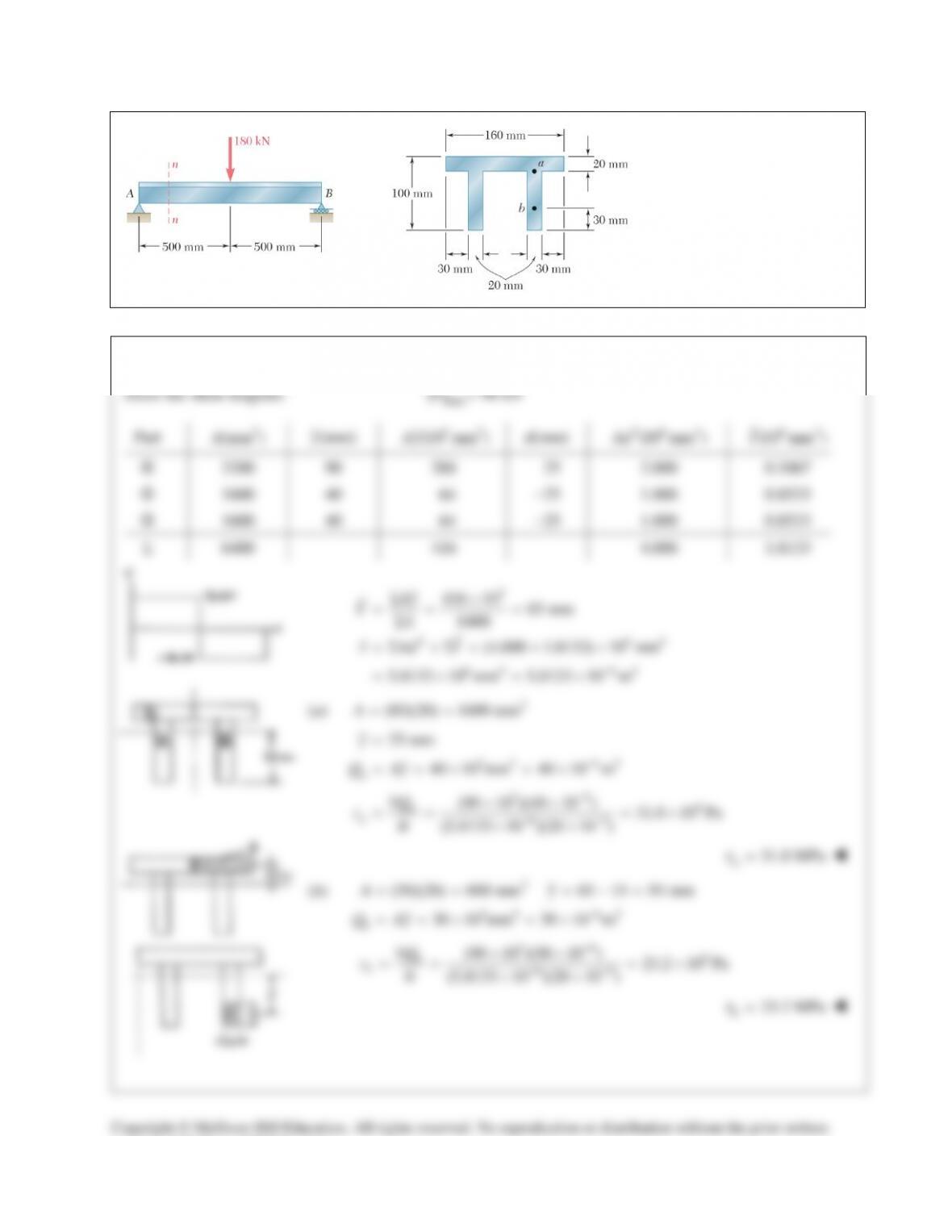
PROBLEM 13.17
For the beam and loading
shown, consider section n–n
and determine the shearing
stress at (a) point a, (b) point b.
SOLUTION
Draw the shear diagram.
max
| | 90 kNV=
Part
2
(mm )A
(mm)y
33
(10 mm )Ay
d(mm)
26 4
(10 mm )Ad
64
(10 mm )I
3200 90 288 25 2.000 0.1067
1600 40 64 −25 1.000 0.8533
1600 40 64 −25 1.000 0.8533
Σ 6400 416 4.000 1.8133
3
2 64
6 4 64
416 10 65 mm
6400
(4.000 1.8133) 10 mm
5.8133 10 mm 5.8133 10 m
Ay
YA
I Ad I
−
Σ×
= = =
Σ
=Σ +Σ = + ×
=×=×
(a)
2
(80)(20) 1600 mmA= =
3 3 63
25 mm
40 10 mm 40 10 m
a
y
Q Ay
−
=
==×=×
36 6
63
(90 10 )(40 10 ) 31.0 10 Pa
(5.8133 10 )(20 10 )
a
a
VQ
It
t
−
−−
××
= = = ×
××
31.0 MPa
a
t
=
(b)
2
3 3 63
(30)(20) 600 mm 65 15 50 mm
30 10 mm 30 10 m
b
Ay
Q Ay
−
= = =−=
==×=×
36 6
63
(90 10 )(30 10 ) 23.2 10 Pa
(5.8133 10 )(20 10 )
b
b
VQ
It
t
−
−−
××
= = = ×
××
23.2 MPa
b
t
=
Copyright © McGraw–Hill Education. All rights reserved. No reproduction or distribution without the prior written
consent of McGraw–Hill Education.
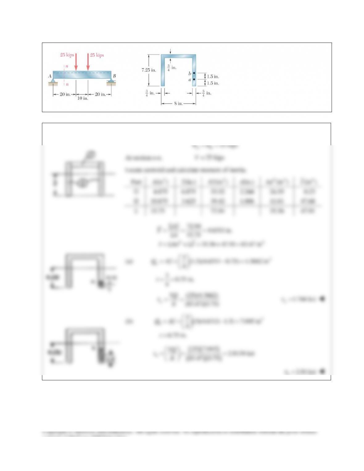
PROBLEM 13.18
For the beam and loading shown,
consider section n–n and determine the
shearing stress at (a) point a, (b) point b.
SOLUTION
25 kips
AB
RR= =
At section n–n,
25 kipsV=
Locate centroid and calculate moment of inertia.
Part
2
(in )A
(in.)
y
3
(in )Ay
d(in.)
24
(in )Ad
4
(in )I
4.875 6.875 33.52 2.244 24.55 0.23
10.875 3.625 39.42 1.006 11.01 47.68
Σ 15.75 72.94 35.56 47.91
24
72.94 4.6311 in.
15.75
35.56 47.91 83.47 in
Ay
YA
I Ad I
Σ
= = =
Σ
=Σ +Σ = + =
(a)
3
3(1.5)(4.6311 0.75) 4.3662 in
4
30.75 in.
4
a
Q Ay
t
== −=
= =
(25)(4.3662)
(83.47)(0.75)
a
VQ
It
t
= =
1.744 ksi
a
t
=
(b)
3
3(3)(4.6311 1.5) 7.045 in
4
0.75 in.
b
Q Ay
t
== −=
=
( )( )
( )( )
25 7.045 2.8134 ksi
83.47 0.75
b
VQ
It
t
= = =
2.81 ksi
b
t
=
consent of McGraw–Hill Education.
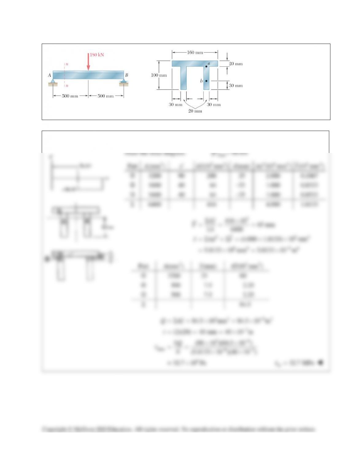
PROBLEM 13.19
For the beam and loading
shown, determine the largest
shearing stress in section n–n.
SOLUTION
consent of McGraw–Hill Education.
PROBLEM 13.11
For the beam and loading
shown, consider section
n-n and determine (a) the
largest shearing stress in
that section, (b
) the
shearing stress at point a.
SOLUTION
At section n–n,
10 kN.V=
12
3 32
11 2 2 2 2
3 32
6 66
6 4 64
4
11
4
12 12
11
(100)(150) 4 (50)(12) (50)(12)(69)
12 12
28.125 10 4 0.0072 10 2.8566 10
39.58 10 mm 39.58 10 m
II I
bh bh Ad
−
= +
=++
=++
= ×+ ×+ ×
=×=×
(a)
11 2 2
3 3 63
2
(100)(75)(37.5) (2)(50)(12)(69)
364.05 10 mm 364.05 10 m
100 mm = 0.100 m
Q Ay Ay
t
−
= +
= +
=×=×
=
36
3
max 6
(10 10 )(364.05 10 ) 920 10 Pa
(39.58 10 )(0.100)
VQ
It
t
−
−
××
= = = ×
×
max
920 kPa
t
=
(b)
11 2 2
3 3 63
2
(100)(40)(55) (2)(50)(12)(69)
302.8 10 mm 302.8 10 m
100 mm 0.100 m
Q Ay Ay
t
−
= +
= +
=×=×
= =
363
6
(10 10 )(302.8 10 ) 765 10 Pa
(39.58 10 )(0.100)
a
VQ
It
t
−
−
××
= = = ×
×
765 kPa
a
t
=
Copyright © McGraw–Hill Education. All rights reserved. No reproduction or distribution without the prior written
consent of McGraw–Hill Education.
PROBLEM 13.12
For the beam and loading shown, consider
section n-n and determine (a) the largest shearing
stress in that section, (b) the shearing stress at
point a.
SOLUTION
0: 2.3 (1.5)(72) 0
46.957 kN
B
MA
Σ=− + =
= ↑A
At section n-n,
46.957 kNVA
= =
Calculate moment of inertia:
3 33
6 4 64
1 11
2 (15)(40) 2 (15)(80) (30)(120 )
12 12 12
5.76 10 mm 5.76 10 m
I
−
=++
=×=×
At a,
33
63
36
6
6
30 mm 0.030 m
(30 20)(50) 30 10 mm
30 10 m
(46.957 10 )(30 10 )
(5.76 10 )(0.030)
8.15 10 Pa = 8.15 MPa
a
a
a
aa
t
Q
VQ
It
t
−
−
−
= =
=×=×
= ×
××
= = ×
= ×
At b,
3 3 3 3 64
36 6
6
60 mm 0.060 m
(60 20)(30) 30 10 36 10 66 10 mm 66 10 m
(46.957 10 )(66 10 ) 8.97 10 Pa 8.97 MPa
(5.76 10 )(0.060)
b
ba
b
bb
t
QQ
VQ
It
t
−
−
−
= =
= + × =× +× =× =×
××
== =×=
×
At NA,
NA
3 3 3 3 63
NA
36 6
NA
NA 6
NA
90 mm 0.090 m
(90 20)(10) 66 10 18 10 84 10 mm 84 10 m
(46.957 10 )(84 10 ) 7.61 10 Pa 7.61 MPa
(5.76 10 )(0.090)
b
t
QQ
VQ
It
t
−
−
−
= =
= + × =× +× =× =×
××
= = =×=
×
(a)
max
t
occurs at b.
max 8.97 MPa
t
=
(b)
8.15 MPa
a
t
=
Copyright © McGraw–Hill Education. All rights reserved. No reproduction or distribution without the prior written
consent of McGraw–Hill Education.
PROBLEM 13.13
For the beam and loading shown, determine the minimum required
depth h, knowing that for the grade of timber used,
all 1750 psi
s
=
and
all
130 psi.
τ
=
SOLUTION
Total load:
3
(750 lb/ft)(16 ft) 12 10 lb= ×
Reaction at A:
3
6 10 lb
A
=×↑R
3
max
33
max
3
6 10 lb
1(8 ft)(6 10 ) 24 10 lb ft
2
288 10 lb in
V
M
= ×
= ×=× ⋅
=×⋅
Bending:
2
1
6
S bh=
for rectangular section.
33
max
all
288 10 164.57 in
1750
6 (6)(164.57) 14.05 in.
5
M
S
S
hb
s
×
= = =
= = =
Shear:
3
1
12
I bh=
for rectangular section.
2
max
max
1
2
1
4
11 1
() 24 8
3
2
A bh
yh
Q Ay b h h bh
VQ V
Ib bh
τ
=
=
= = =
= =
3
max
max
3 (3)(6 10 ) 13.85 in.
2 (2)(5)(130)
V
hb
τ
×
= = =
The larger value of h is the minimum required depth.
14.05 in.h=
consent of McGraw–Hill Education.
PROBLEM 13.14
For the beam and loading shown, determine the minimum
required width b, knowing that for the grade of timber
used,
all
12 MPa
σ
=
and
all
825 kPa.
τ
=
SOLUTION
0: 3 (2)(2.4) (1)(4.8) 0
3.2 kN
DA
A
MR
R
=−+ + =
=
Draw shear and bending moment diagrams.
max max
4.0 kN 4.0 kN mVM= = ⋅
Bending:
3
max 6
all
63 3 3
4.0 10
12 10
333.33 10 m 333.33 10 mm
M
S
σ
−
×
= = ×
=×=×
For a rectangular cross section,
3
2
3
22
23
3
3
32 3 2
3
11
12
16
2
6 (6)(333.33 10 ) 88.9 mm
150
11
,
24
11
,
8 12
3
2
3 3 4.0 10
22
825 10
7.2727 10 m 7.2727 10 mm
7.2727 10 48.5 mm
150
bh
I
S bh
ch
S
bh
A bh y h
Q Ay bh I bh
VQ V
It bh
V
bh
bh
bh
τ
τ
−
= = =
×
= = =
= =
= = =
= =
×
= = ×
=×=×
×
= = =
The required value for b is the larger one.
88.9 mmb=
consent of McGraw–Hill Education.
PROBLEM 13.15
For the wide–flange beam with the loading shown, determine the
largest load P that can be applied, knowing that the maximum
normal stress is 24 ksi and the largest shearing stress using the
approximation
web
/
m
VA
τ
=
is 14.5 ksi.
SOLUTION
0: 15 0
0.6
CA
A
M R qP
RP
=− +=
=
∑
Draw shear and bending moment diagrams.
max max
0.6 0.6
6ft 72 in.
AB
AB
V P M PL
L
= =
= =
Bending. For
W24 104×
,
3
258 inS=
max
all all
all
0.6
(24)(258) 143.3 kips
0.6 (0.6)(72)
AB
AB
MPL
S
S
PL
ss
s
= =
= = =
Shear.
web
2
(24.1)(0.500)
12.05 in
w
A dt
=
=
=
max
web web
web
0.6
(14.5)(12.05) 291kips
0.6 0.6
VP
AA
A
P
τ
τ
= =
= = =
The smaller value of P is the allowable value.
143.3 kipsP=
consent of McGraw–Hill Education.
PROBLEM 13.16
For the wide–flange beam with the loading shown, determine the
largest load P that can be applied, knowing that the maximum
normal stress is 160 MPa and the largest shearing stress using the
approximation
web
/
m
VA
τ
=
is 100 MPa.
SOLUTION
0: 3.6 3.0 2.4 1.8 0
2
EA
A
M R PPP
RP
=− +++=
= ↑
∑
Draw shear and bending moment diagrams.
max max
2, 3
23
B AB C D AB
AB
M PL M M PL
V P M PL
= = =
= =
Bending. For
W360 122,
×
33
63
= 2020 10 mm
= 2020 10 m
S
−
×
×
max
all all
63 3
all
3
(160 10 )(2020 10 ) 179.6 10 N
3 (3)(0.6)
AB
AB
MPL S
S
PL
σσ
σ
= =
××
= = = ×
Shear.
web
3 2 32
(363)(13.0)
4.719 10 mm 4.719 10 m
w
A dt
−
= =
=×=×
max
web web
63
3
web
2
(100 10 )(4.719 10 ) 236 10 N
22
VP
AA
A
P
τ
τ
−
= =
××
= = = ×
The smaller value of P is the allowable one.
179.6 kNP=
Copyright © McGraw–Hill Education. All rights reserved. No reproduction or distribution without the prior written
consent of McGraw–Hill Education.
PROBLEM 13.17
For the beam and loading
shown, consider section n–n
and determine the shearing
stress at (a) point a, (b) point b.
SOLUTION
Draw the shear diagram.
max
| | 90 kNV=
Part
2
(mm )A
(mm)y
33
(10 mm )Ay
d(mm)
26 4
(10 mm )Ad
64
(10 mm )I
3200 90 288 25 2.000 0.1067
1600 40 64 −25 1.000 0.8533
1600 40 64 −25 1.000 0.8533
Σ 6400 416 4.000 1.8133
3
2 64
6 4 64
416 10 65 mm
6400
(4.000 1.8133) 10 mm
5.8133 10 mm 5.8133 10 m
Ay
YA
I Ad I
−
Σ×
= = =
Σ
=Σ +Σ = + ×
=×=×
(a)
2
(80)(20) 1600 mmA= =
3 3 63
25 mm
40 10 mm 40 10 m
a
y
Q Ay
−
=
==×=×
36 6
63
(90 10 )(40 10 ) 31.0 10 Pa
(5.8133 10 )(20 10 )
a
a
VQ
It
t
−
−−
××
= = = ×
××
31.0 MPa
a
t
=
(b)
2
3 3 63
(30)(20) 600 mm 65 15 50 mm
30 10 mm 30 10 m
b
Ay
Q Ay
−
= = =−=
==×=×
36 6
63
(90 10 )(30 10 ) 23.2 10 Pa
(5.8133 10 )(20 10 )
b
b
VQ
It
t
−
−−
××
= = = ×
××
23.2 MPa
b
t
=
Copyright © McGraw–Hill Education. All rights reserved. No reproduction or distribution without the prior written
consent of McGraw–Hill Education.
PROBLEM 13.18
For the beam and loading shown,
consider section n–n and determine the
shearing stress at (a) point a, (b) point b.
SOLUTION
25 kips
AB
RR= =
At section n–n,
25 kipsV=
Locate centroid and calculate moment of inertia.
Part
2
(in )A
(in.)
y
3
(in )Ay
d(in.)
24
(in )Ad
4
(in )I
4.875 6.875 33.52 2.244 24.55 0.23
10.875 3.625 39.42 1.006 11.01 47.68
Σ 15.75 72.94 35.56 47.91
24
72.94 4.6311 in.
15.75
35.56 47.91 83.47 in
Ay
YA
I Ad I
Σ
= = =
Σ
=Σ +Σ = + =
(a)
3
3(1.5)(4.6311 0.75) 4.3662 in
4
30.75 in.
4
a
Q Ay
t
== −=
= =
(25)(4.3662)
(83.47)(0.75)
a
VQ
It
t
= =
1.744 ksi
a
t
=
(b)
3
3(3)(4.6311 1.5) 7.045 in
4
0.75 in.
b
Q Ay
t
== −=
=
( )( )
( )( )
25 7.045 2.8134 ksi
83.47 0.75
b
VQ
It
t
= = =
2.81 ksi
b
t
=
consent of McGraw–Hill Education.
PROBLEM 13.19
For the beam and loading
shown, determine the largest
shearing stress in section n–n.
SOLUTION
consent of McGraw–Hill Education.