Archives: Solution Manual
Chapter 9 Homework Sketch The Body And Show The Orientation
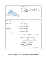
PROBLEM 9.180 For the component described in Problem 9.165, determine (a) the principal mass moments of inertia at the origin, (b) the principal axes of inertia at the origin. Sketch the body and show the orientation of the principal axes […]
Chapter 9 Homework Now Observe That The Centroidal Products Inertia
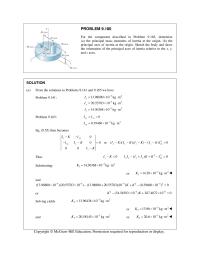
PROBLEM 9.169 Determine the mass moment of inertia of the machine component of Problems 9.136 and 9.155 with respect to the axis through the origin characterized by the unit vector (4 8 )/9. λijk SOLUTION From the solutions to […]
Chapter 9 Homework Thin aluminum wire of uniform diameter is used to
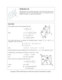
PROBLEM 9.158 Thin aluminum wire of uniform diameter is used to form the figure shown. Denoting by m the mass per unit length of the wire, determine the mass products of inertia I xy , I yz , and I […]
Chapter 9 Homework Solution First Compute The Mass Each Component
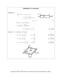
PROBLEM 9.146 (Continued) 24 35 12345 2 32 2 () (), () () () () () () () 1 ft [(8.5857 10 lb s /ft)(16 in.) ] 12 in. yy yy yy y y y y II II II I […]
Chapter 8 Homework Ef Matter How Large How Small Is
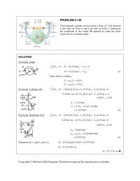
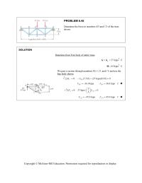
PROBLEM 8.138 The hydraulic cylinder shown exerts a force of 3 kN directed to the right on Point B and to the left on Point E. Determine the magnitude of the couple M required to rotate the drum clockwise at […]
Chapter 8 Homework The speed of the brake drum shown is controlled by
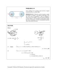
PROBLEM 8.114 Solve Problem 8.113 assuming that the belt is looped around the pulleys in a figure eight. PROBLEM 8.113 A flat belt is used to transmit a couple from pulley A to pulley B. The radius of each pulley […]
Chapter 8 Homework A scooter is to be designed to roll down
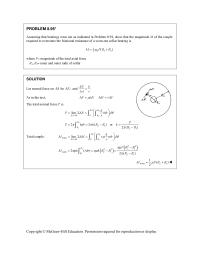
PROBLEM 8.95* Assuming that bearings wear out as indicated in Problem 8.94, show that the magnitude M of the couple required to overcome the frictional resistance of a worn-out collar bearing is 1 12 2 () k MPRR […]
Chapter 8 Homework A flat belt is used to transmit a couple from drum B
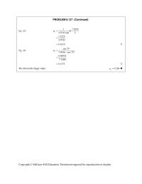
PROBLEM 8.127 (Continued) Eq. (3): 17.5056 ln 4.9742 rad 2 1.3225 4.9742 s 0.2659 Eq. (4): sin 75 7.5056 cos 75 0.96953 7.2468 s 0.1333 We choose the larger […]
Chapter 8 Homework Since Pff Machine Base Will Not Move
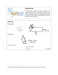
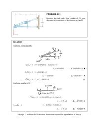
PROBLEM 8.60 The spring of the door latch has a constant of 1.8 lb/in. and in the position shown exerts a 0.6-lb force on the bolt. The coefficient of static friction between the bolt and the strike plate is 0.40; […]
Chapter 8 Homework Find P required to start raising load
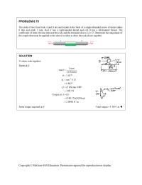
PROBLEM 8.75 The ends of two fixed rods A and B are each made in the form of a single-threaded screw of mean radius 6 mm and pitch 2 mm. Rod A has a right-handed thread and rod B has […]
Chapter 8 Homework For Motion Impending Right From Solution Prob
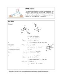
PROBLEM 8.46 Two slender rods of negligible weight are pin-connected at C and attached to blocks A and B, each of weight W. Knowing that 80 and that the coefficient of static friction between the blocks and […]
Chapter 8 Homework Determine E the largest allowable value of the coefficient
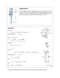
PROBLEM 8.33 A pipe of diameter 60 mm is gripped by the stillson wrench shown. Portions AB and DE of the wrench are rigidly attached to each other, and portion CF is connected by a pin at D. If the […]
Chapter 8 Homework A worker slowly moves a 50-kg crate to the left along
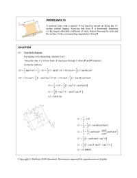
PROBLEM 8.15 A uniform crate with a massof 30 kg must be moved up along the 15° incline without tipping. Knowing that force P is horizontal, determine (a) the largest allowable coefficient of static friction between the crate and the […]
Chapter 8 Homework The weight of block E and the friction in the pulleys
CHAPTER 8 PROBLEM 8.1 Determine whether the block shown is in equilibrium and find the magnitude and direction of the friction force whenP 150 N. SOLUTION Assume equilibrium: 0: (500 N)sin 20 (150 N) cos 20 0 x FF […]
Chapter 7 Homework Determine the sag-to-span ratio for which the maximum
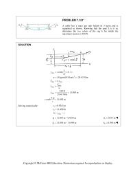
PROBLEM 7.151* A cable has a mass per unit length of 3 kg/m and is supported as shown. Knowing that the span L is 6 m, determine the two values of the sag h for which the maximum tension is […]
Chapter 7 Homework A counterweight D is attached to a cable that passes
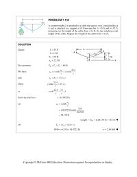
PROBLEM 7.135 A counterweight D is attached to a cable that passes over a small pulley at A and is attached to a support at B. Knowing that L= 45 ft and h= 15 ft, determine (a) the length of […]
Chapter 7 Homework T0 is The Tension The Lowest Point Solution
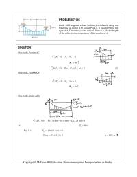
PROBLEM 7.116 Cable ACB supports a load uniformly distributed along the horizontal as shown. The lowest Point C is located 9 m to the right of A. Determine (a) the vertical distance a, (b) the length of the cable, (c) […]
Chapter 7 Homework Cable ABC supports two loads as shown
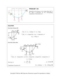
PROBLEM 7.100 Determine (a) the distance dC for which portion BC of the cable is horizontal, (b) the corresponding components of the reaction at E. SOLUTION Free body: Portion CDE 0: 2(2 kips) 0 4 kips yy y FE EΣ= […]

Chapter 7 Homework Pand B Draw The Shear And Bendingmoment
PROBLEM 7.87 For the beam and loading shown, (a) write the equations of the shear and bending-moment curves, (b) determine the magnitude and location of the maximum bending moment. SOLUTION (a) We check that beam is in equilibrium ( ) […]
Chapter 7 Homework From the values obtained for its left-hand half
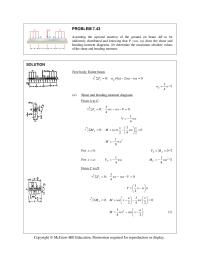
PROBLEM 7.43 Assuming the upward reaction of the ground on beam AB to be uniformly distributed and knowing that P =wa, (a) draw the shear and bending-moment diagrams, (b) determine the maximum absolute values of the shear and bending moment. […]
Chapter 7 Homework Shear and bending-moment diagrams From A to C
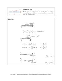
PROBLEM 7.30 For the beam and loading shown, (a) draw the shear and bending- moment diagrams, (b) determine the maximum absolute values of the shear and bending moment. SOLUTION Copyright © McGraw–Hill Education. Permission required for reproduction or display. 2 […]
Chapter 7 Homework We recall that the forces applied to a pulley may
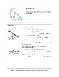
PROBLEM 7.16 Knowing that the radius of each pulley is 200 mm and neglecting friction, determine the internal forces at Point K of the frame shown. SOLUTION Free body: frame and pulleys 0: (1.8 m) (360 N)(0.2 m) (360 N)(2.6 […]
Chapter 7 Homework D Maximum Bending Moment M 960
CHAPTER 7 PROBLEM 7.1 Determine the internal forces (axial force, shearing force, and bending moment) at Point J of the structure indicated. Frame and loading of Problem 6.76. SOLUTION From Problem 6.76: 720 lb x=C 140 lb y =C Copyright […]
Chapter 7 Homework Minimum value of B.M. For M to have negative values
PROBLEM 7.54 Solve Problem 7.53 when 60 . θ = ° PROBLEM 7.53 Two small channel sections DF and EH have been welded to the uniform beam AB of weight W 3 kN= to form the rigid structural member shown. […]
Chapter 7 Homework Draw the shear and bending-moment diagrams
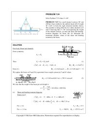
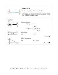
PROBLEM 7.68 Using the method of Section 7.6, solve Problem 7.34. PROBLEM 7.34 For the beam and loading shown, (a) draw the shear and bending-moment diagrams, (b) determine the maximum absolute values of the shear and bending moment. SOLUTION Free […]
Chapter 6 Homework We note that AB, BC, and FG are two-force members
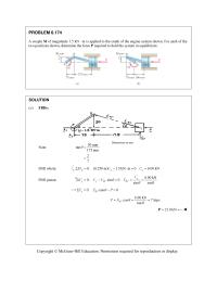
PROBLEM 6.174 A couple M of magnitude 1.5 kN m is applied to the crank of the engine system shown. For each of the two positions shown, determine the force P required to hold the system in equilibrium. SOLUTION […]
Chapter 6 Homework Member of the double-pitch roof truss shown
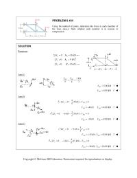
PROBLEM 6.164 Using the method of joints, determine the force in each member of the truss shown. State whether each member is in tension or compression. SOLUTION Reactions: 0: 16 kN Cx M A 0: 9 kN yy F A […]
Chapter 6 Homework The Arms Are Located In Symmetrically With
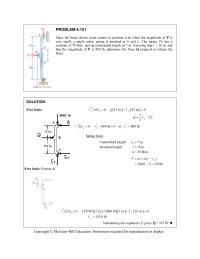
PROBLEM 6.151 Since the brace shown must remain in position even when the magnitude of P is very small, a single safety spring is attached at D and E. The spring DE has a constant of 50 lb/in. and an […]
Chapter 6 Homework The Whitworth mechanism shown is used to produce
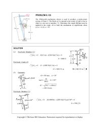
PROBLEM 6.133 The Whitworth mechanism shown is used to produce a quick-return motion of Point D. The block at B is pinned to the crank AB and is free to slide in a slot cut in member CD. Determine the […]
Chapter 6 Homework Solution Note All Three Cases The Right
PROBLEM 6.118 (Continued) Member AFB: 0: 0 y FFABP 80 33 EE FP 3FP E (3) 0: ( ) (3 ) 0 A MFaBa 8 (3)() (3)0 […]
Chapter 6 Homework The components of the force exerted at B on 8 m
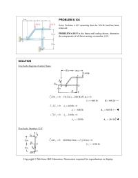
PROBLEM 6.104 Solve Problem 6.103 assuming that the 360-lb load has been removed. PROBLEM 6.103 For the frame and loading shown, determine the components of all forces acting on member ABD. SOLUTION Free body diagram of entire frame. 0: (12 […]
Chapter 6 Homework Free Body Member ABC Note Two force Member
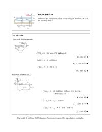
PROBLEM 6.78 Determine the components of all forces acting on member ABCD of the assembly shown. SOLUTION Free body: Entire assembly: 0: (6 in.) (120 lb)(4 in.) 0 B MD 80.0 lb D 0: 120 lb 0 […]
Chapter 6 Homework Kips Portion to the left of vertical cut through panel
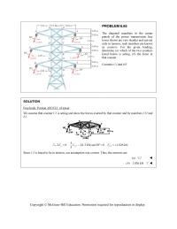
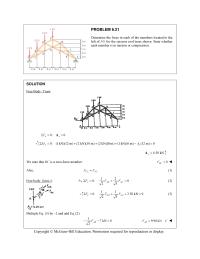
PROBLEM 6.65 The diagonal members in the center panels of the power transmission line tower shown are very slender and can act only in tension; such members are known as counters. For the given loading, determine (a) which of the […]
Chapter 6 Homework DF, DG, and EG and use the free body shown
PROBLEM 6.45 Determine the force in members BD and CD of the truss shown. SOLUTION 45 kipsH We pass a section through members BD, CD, and CE and use the free body shown. 0: (7.5 ft) (27 kips)(10 ft) […]
Chapter 6 Homework The truss shown consists of six members
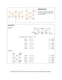
PROBLEM 6.33 For the given loading, determine the zero-force members in each of the two trusses shown. SOLUTION Truss (a): Note: Reaction at F is vertical (0). x F Joint :G 0,F 0 DG F Joint :D 0,F 0 […]
Chapter 6 Homework Knowing That The Combined Weight The Pipe
PROBLEM 6.91 Knowing that each pulley has a radius of 250 mm, determine the components of the reactions at D and E. SOLUTION Free body: Entire assembly: 0: (4.8 kN)(4.25 m) (1.5 m) 0 Ex MD 13.60 kN […]
Chapter 6 Homework Members located to the left of DE for the inverted
PROBLEM 6.21 Determine the force in each of the members located to the left of FG for the scissors roof truss shown. State whether each member is in tension or compression. SOLUTION Free Body: Truss: 0: 0 xx F A […]
Chapter 6 Homework By symmetry about the horizontal centerline
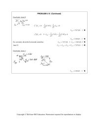
PROBLEM 6.10 (Continued) Free body: Joint B: 11 0: 7.07 0 22 yBD FF 7.07 kN BD FT 11 0: 5 (7.07) 7.07 0 22 xBA FF 5.00 kN BA FC […]
Chapter 6 Homework Determine the force in each a B C member of the truss shown
CHAPTER 6 PROBLEM 6.1 Using the method of joints, determine the force in each member of the truss shown. State whether each member is in tension or compression. SOLUTION Free body: Entire truss: 0: 0 0 yy y FB […]
Chapter 5 Homework A decorative plate placed on a pipe where 25 mm
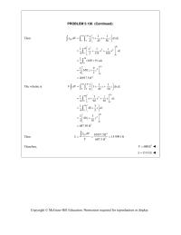
PROBLEM 5.136 (Continued) Then 50 30 00 11 1 44550 EL x x dV x z dx dz 30 2 50 32 00 50 0 50 2 0 4 19 650 42 10937.5 ft zz […]
Chapter 5 Homework Solution Choose The Element Horizontal Slice Thickness
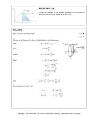
PROBLEM 5.128* Locate the centroid of the volume generated by revolving the portion of the sine curve shown about the x-axis. SOLUTION First, note that symmetry implies 0y 0z Choose as the element of volume a disk of […]
Chapter 5 Homework Locate the center of gravity of the portion of the frame
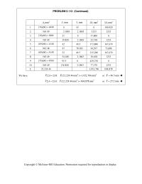
PROBLEM 5.113 (Continued) 2 ,mmA ,mm x ,mm y 3 ,mmxA 3 ,mmyA 1 (74)(60) 4440 0 43 0 190,920 2 565.49 2.1803 2.1803 1233 1233 3 (30)(60) 1800 21 0 37,800 0 4 565.49 39.820 2.1803 22,518 1233 5 […]
Chapter 5 Homework Locate the y coordinate of the center of gravity
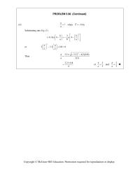
PROBLEM 5.98 (Continued) (b) ?when 0.4 hYa a Substituting into Eq. (1) 2 3 (0.4)4 4 8 hh aa aa or 2 33.20.80 hh aa […]
Chapter 5 Homework If the tank is slowly filled with water
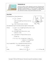
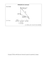
PROBLEM 5.83 The base of a dam for a lake is designed to resist up to 120 percent of the horizontal force of the water. After construction, it is found that silt (that is equivalent to a liquid of density […]
Chapter 5 Homework First replace the given loading by the loadings shown
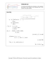
PROBLEM 5.66 For the beam and loading shown, determine (a) the magnitude and location of the resultant of the distributed load, (b) the reactions at the beam supports. SOLUTION I II 1 ( ) (400 N/m) (6 m) 2 1200 […]
Chapter 5 Homework Y4 are measured with respect to line
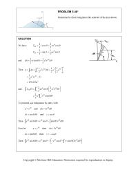
PROBLEM 5.48* Determine by direct integration the centroid of the area shown. SOLUTION We have 22 cos cos 33 22 sin sin 33 EL EL xr ae yr ae and 22 11 ()( ) […]
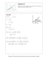
Chapter 5 Homework Express your answer in terms of
PROBLEM 5.35 Determine by direct integration the centroid of the area shown. Express your answer in terms of a and h. SOLUTION At (, ),ah 2 1 :yhka or 2 h ka 2 :yhma or h ma Now […]
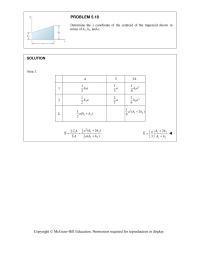
Chapter 5 Homework A collar B of weight W can move freely along the vertical
PROBLEM 5.18 Determine the x coordinate of the centroid of the trapezoid shown in terms of h1, h2, and a. SOLUTION Area 1: A x x A 1 1 1 2ha 1 3a 2 1 1 6ha 2 2 1 […]

Chapter 5 Homework Locate The Centroid The Plane Area Shown
CHAPTER 5 PROBLEM 5.1 Locate the centroid of the plane area shown. SOLUTION Area 1: Rectangle 72 mm by 45 mm. Area 2: Triangle b = 27 mm, h = 45 mm. 2 ,mmA ,mm x ,mm y 3 ,mmxA […]
Chapter 4 Homework A collar B of weight W can move freely along the vertical
PROBLEM 4.68 (Continued) Force Triangle Law of sines: 150 lb sin 29.745 sin116.565 sin 33.690 CD 270.42 lb, 167.704 lb C D 270 lbC 56.3 ; 167.7 lbD26.6 Copyright © McGraw-Hill Education. Permission required for […]