PROBLEM 7.87
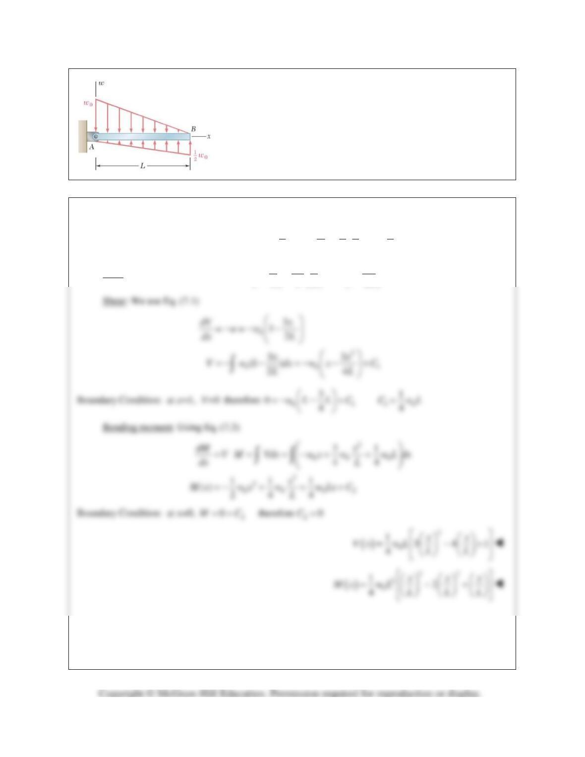
For the beam and loading shown, (a) write the equations of the shear
and bending-moment curves, (b) determine the magnitude and
location of the maximum bending moment.
SOLUTION
(a) We check that beam is in equilibrium
( )
00
1 11 2 0
2 3 22 3
L
wL wL L
−+ =
(ok)
Load:
0
00
3
() 1 1
22
w
xx x
wx w w
LL L
= −− = −
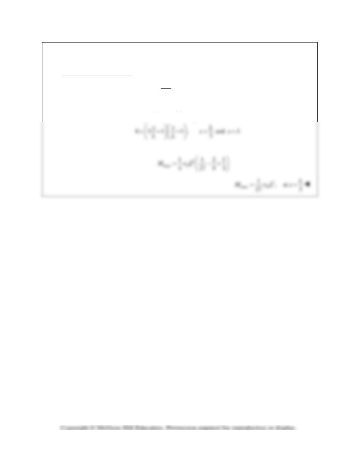
PROBLEM 7.87 (Continued)
(b) Maximum bending moment
0
dM V
dx = =
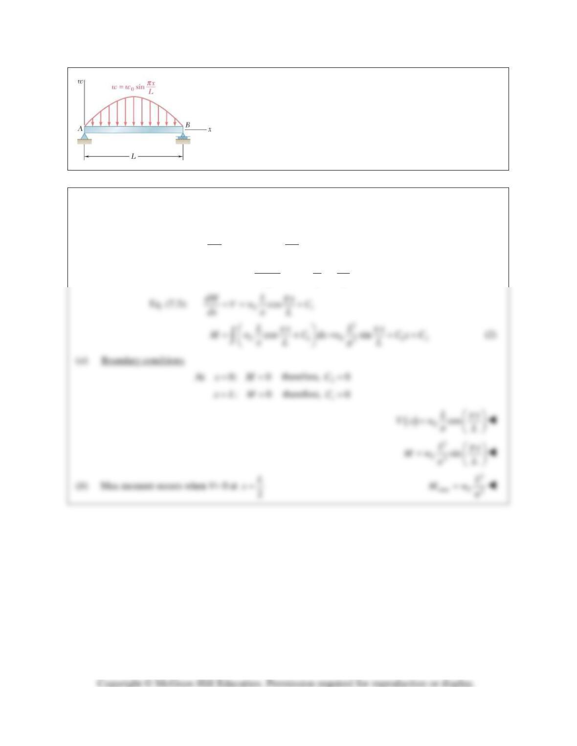
PROBLEM 7.88
For the beam and loading shown, (a) write the equations of the shear
and bending-moment curves, (b) determine the magnitude and
location of the maximum bending moment.
SOLUTION
Eq. (7.1):
0sin
dV x
ww
dx L
π
=−=−
0 01
sin cos
x Lx
V w dx w C
LL
ππ
π
=−= +
∫
(1)
PROBLEM 7.89
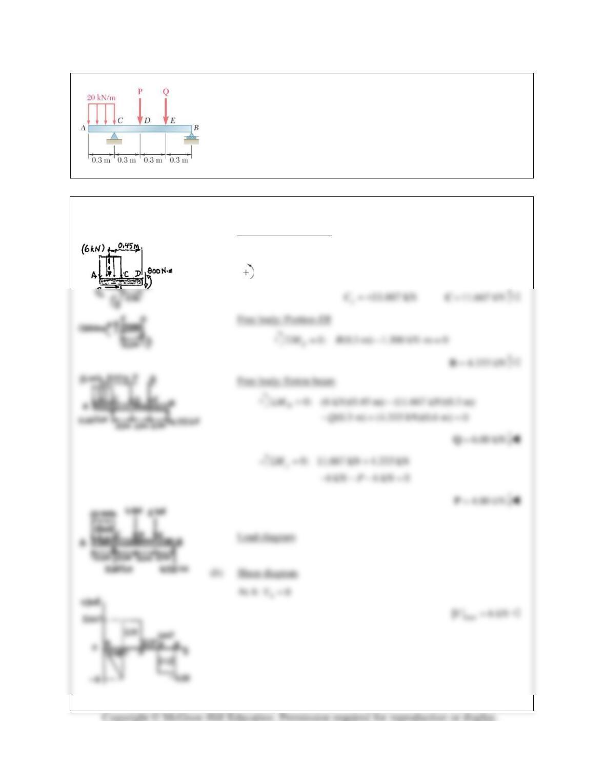
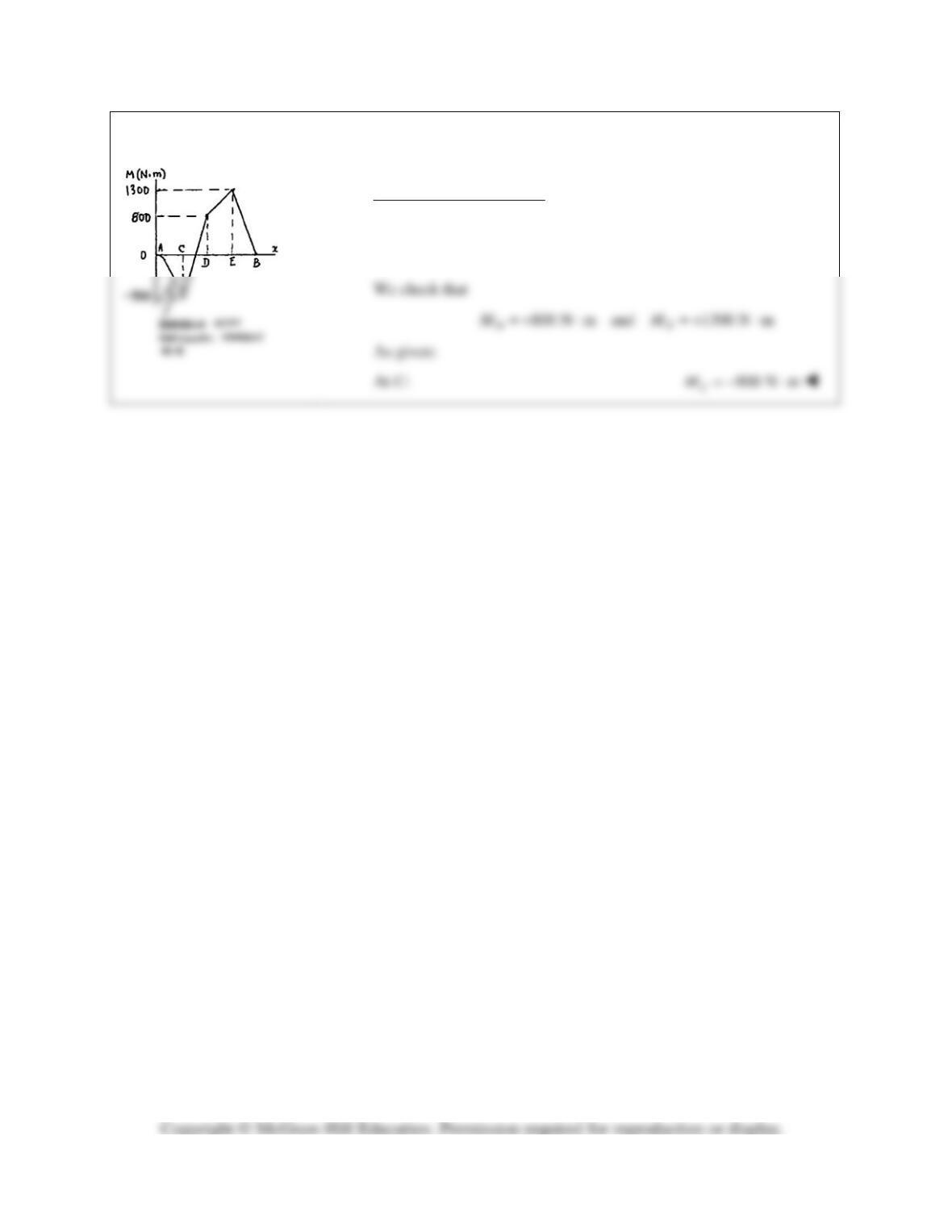
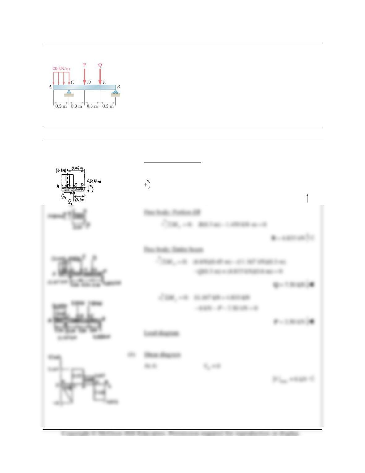
The beam AB is subjected to the uniformly distributed load shown and to
two unknown forces P and Q. Knowing that it has been experimentally
determined that the bending moment is
800 N m+⋅
at D and
1300 N m+⋅
at E, (a) determine P and Q, (b) draw the shear and bending-moment
diagrams for the beam.
SOLUTION
(a) Free body: Portion AD
0: 0
xx
FCΣ= =
0: (0.3 m) 0.800 kN m (6 kN)(0.45 m) 0
Dy
MCΣ = − + ⋅+ =
PROBLEM 7.89 (Continued)
Bending-moment diagram
At A:
0
A
M=
max
| | 1300 N mM= ⋅
PROBLEM 7.90
Solve Problem 7.89 assuming that the bending moment was found to
be
650 N m+⋅
at D and
1450 N m+⋅
at E.
PROBLEM 7.89 The beam AB is subjected to the uniformly distributed
load shown and to two unknown forces P and Q. Knowing that it has
been experimentally determined that the bending moment is
800 N m+⋅
at D and
1300 N m+⋅
at E, (a) determine P and Q, (b) draw the shear
and bending-moment diagrams for the beam.
SOLUTION
(a) Free body: Portion AD
0: 0
xx
FCΣ= =
0: (0.3 m) 0.650 kN m (6 kN)(0.45 m) 0
D
MCΣ = − + ⋅+ =
11.167 kN= +
y
C
11.167 kN=C
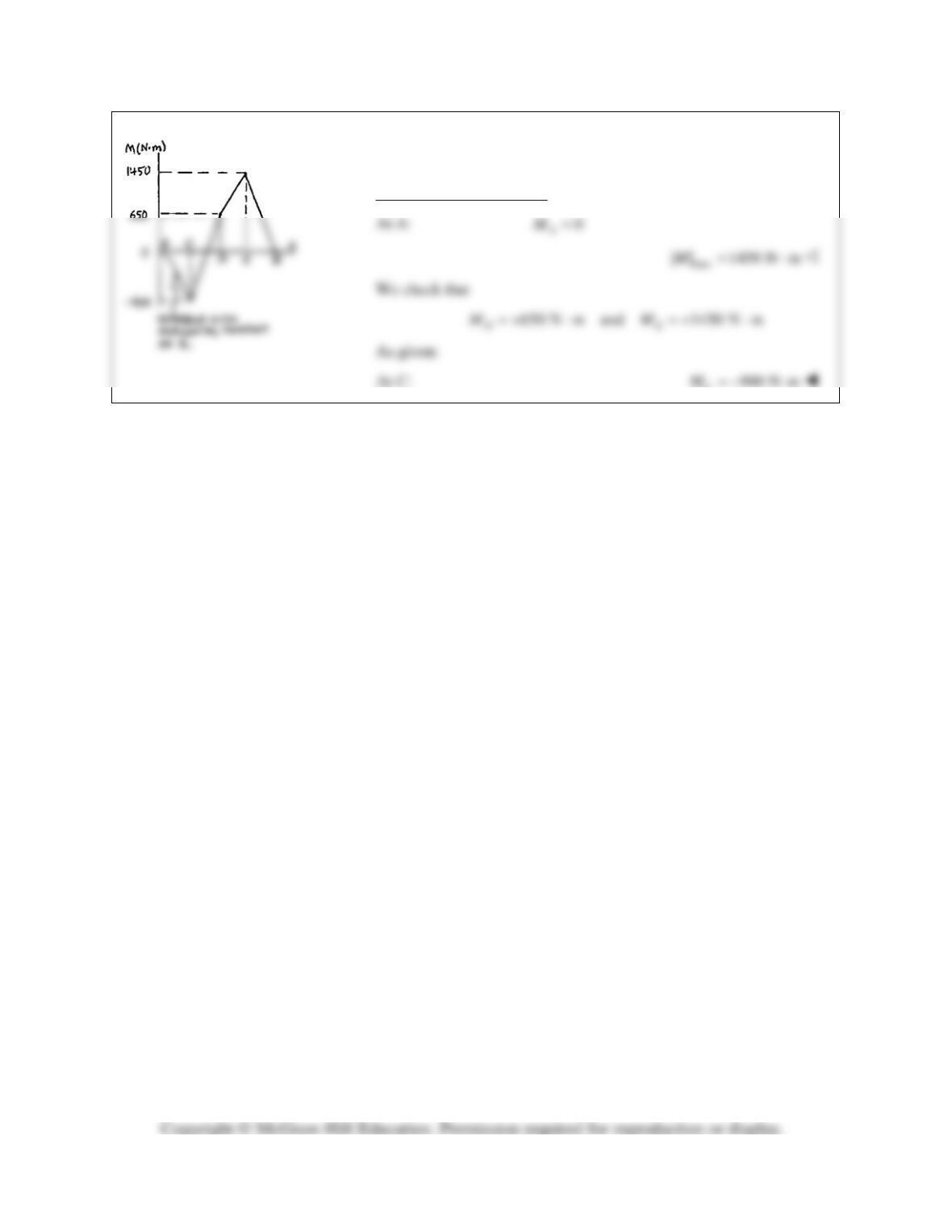
PROBLEM 7.90 (Continued)
Bending-moment diagram
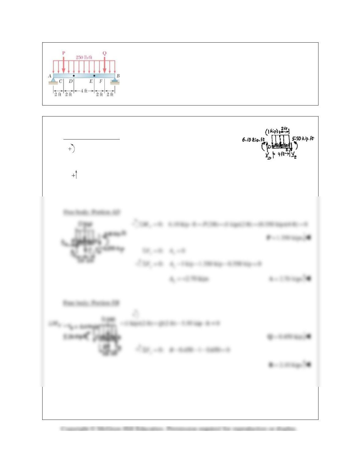
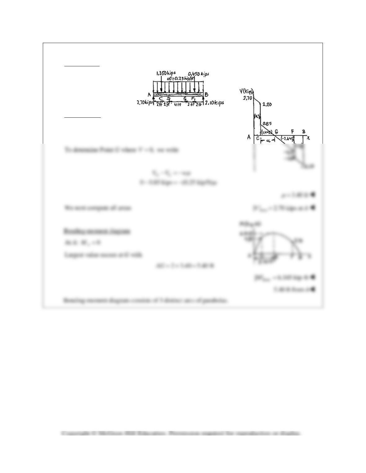
PROBLEM 7.91*
The beam AB is subjected to the uniformly distributed load shown and to
two unknown forces P and Q. Knowing that it has been experimentally
determined that the bending moment is
6.10 kip ft+⋅
at D and
5.50 kip ft+⋅
at E, (a) determine P and Q, (b) draw the shear and
bending-moment diagrams for the beam.
SOLUTION
(a) Free body: Portion DE
0: 5.50 kip ft 6.10 kip ft (1 kip)(2 ft) (4 ft)0
ED
MVΣ = ⋅− ⋅+ − =
0.350 kip
D
V= +
0: 0.350 kip 1kip 0
yE
FVΣ= − − =
0.650 kip
E
V= −
PROBLEM 7.91* (Continued)
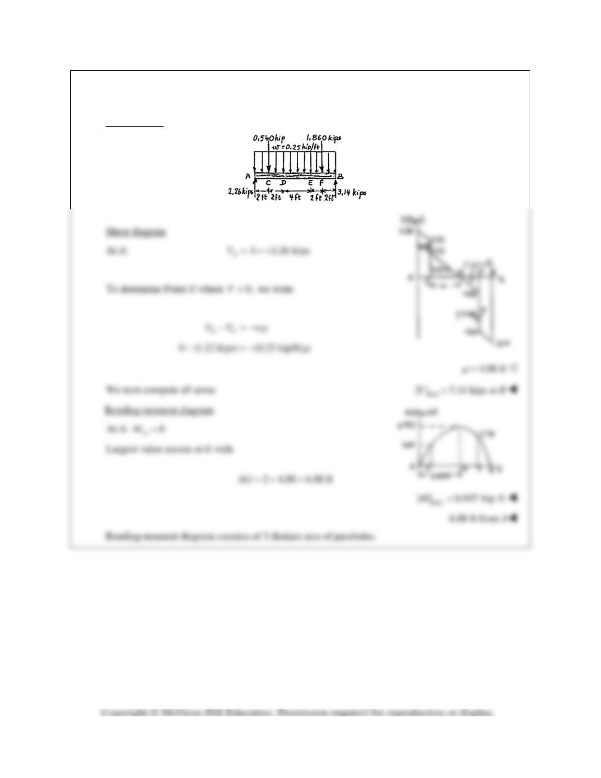
(b) Load diagram
Shear diagram
At A:
2.70 kips
A
VA= = +
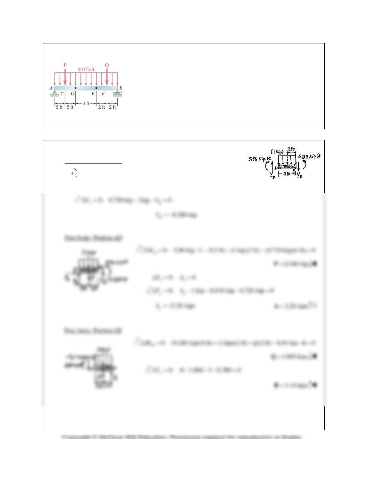
PROBLEM 7.92*
Solve Problem 7.91 assuming that the bending moment was found to
be
5.96 kip ft+⋅
at D and
6.84 kip ft+⋅
at E.
PROBLEM 7.91* The beam AB is subjected to the uniformly
distributed load shown and to two unknown forces P and Q. Knowing
that it has been experimentally determined that the bending moment is
6.10 kip ft+⋅
at D and
5.50 kip ft+⋅
at E, (a) determine Pand Q, (b) draw
the shear and bending–moment diagrams for the beam.
SOLUTION
(a) Free body: Portion DE
0: 6.84 kip ft 5.96 kip ft (1 kip)(2 ft) (4 ft)0
ED
MVΣ = ⋅− ⋅+ − =
0.720 kip
D
V= +
PROBLEM 7.92* (Continued)
(b) Load diagram
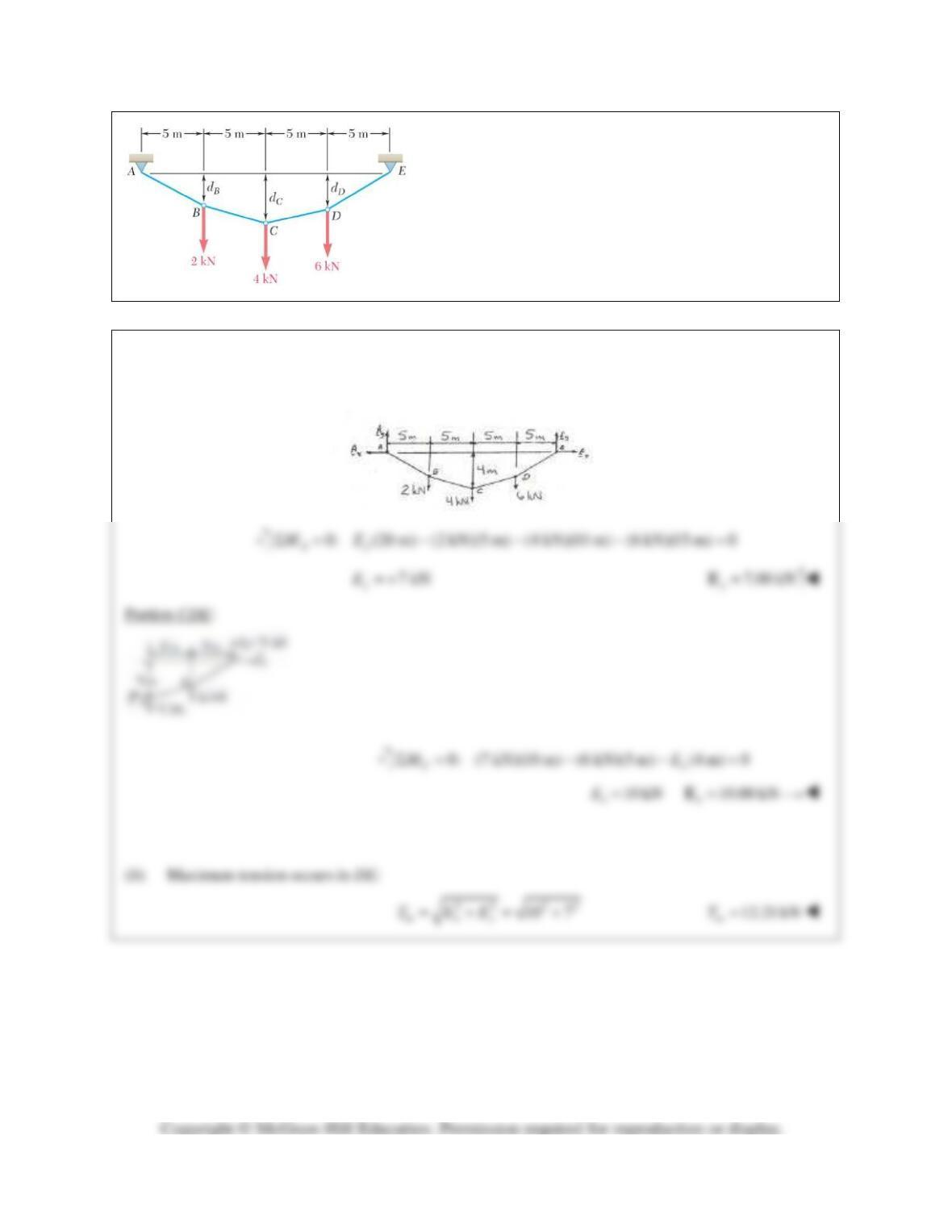
PROBLEM 7.93
Three loads are suspended as shown from the cable
ABCDE. Knowing that dC= 4 m, determine (a) the
components of the reaction at E, (b) the maximum tension
in the cable.
SOLUTION
(a)
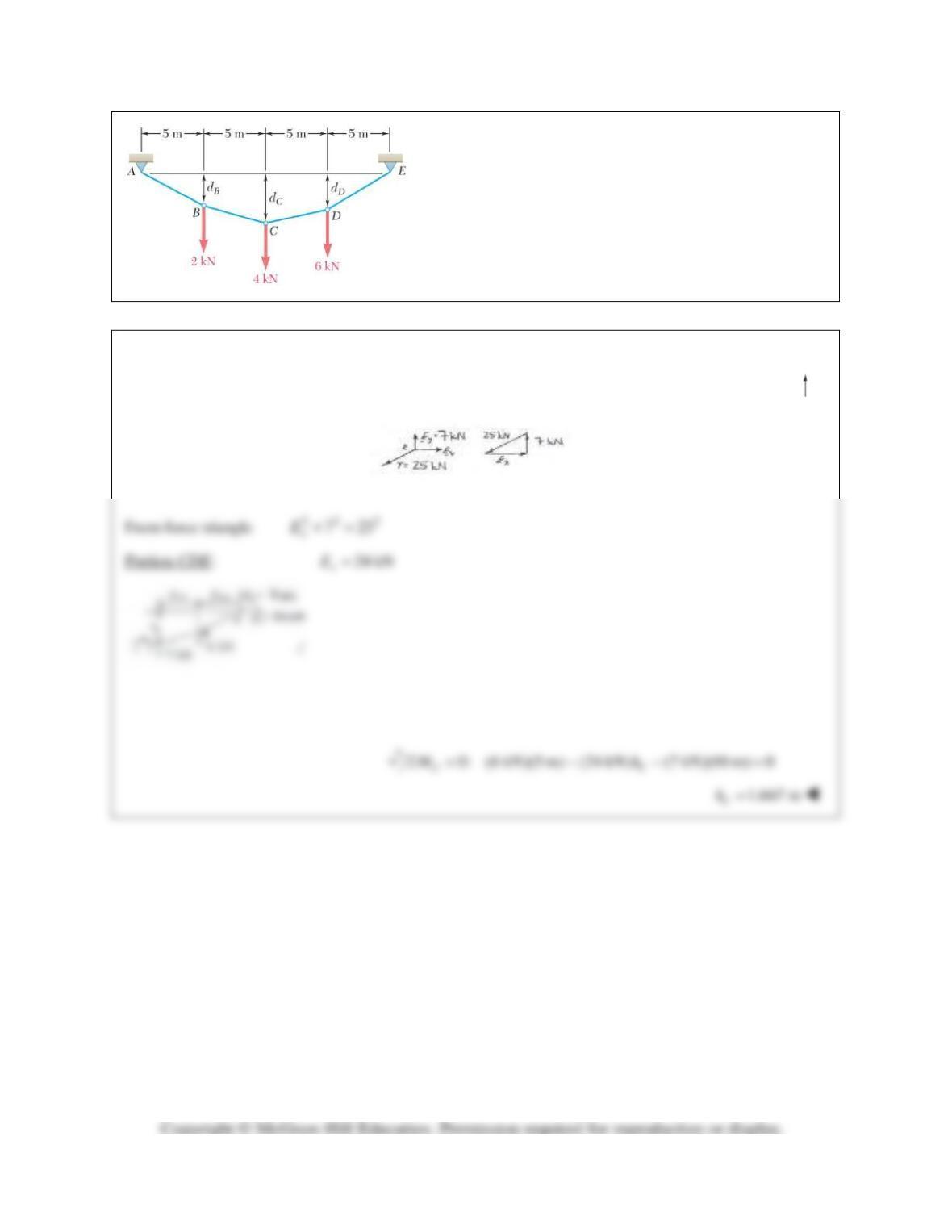
PROBLEM 7.94
Knowing that the maximum tension in cable ABCDE is
25 kN, determine the distance dC.
SOLUTION
Maximum T of 25 kN occurs in DE. See solution of Problem 7.93 for the determination of
7.00 kN
y
=E
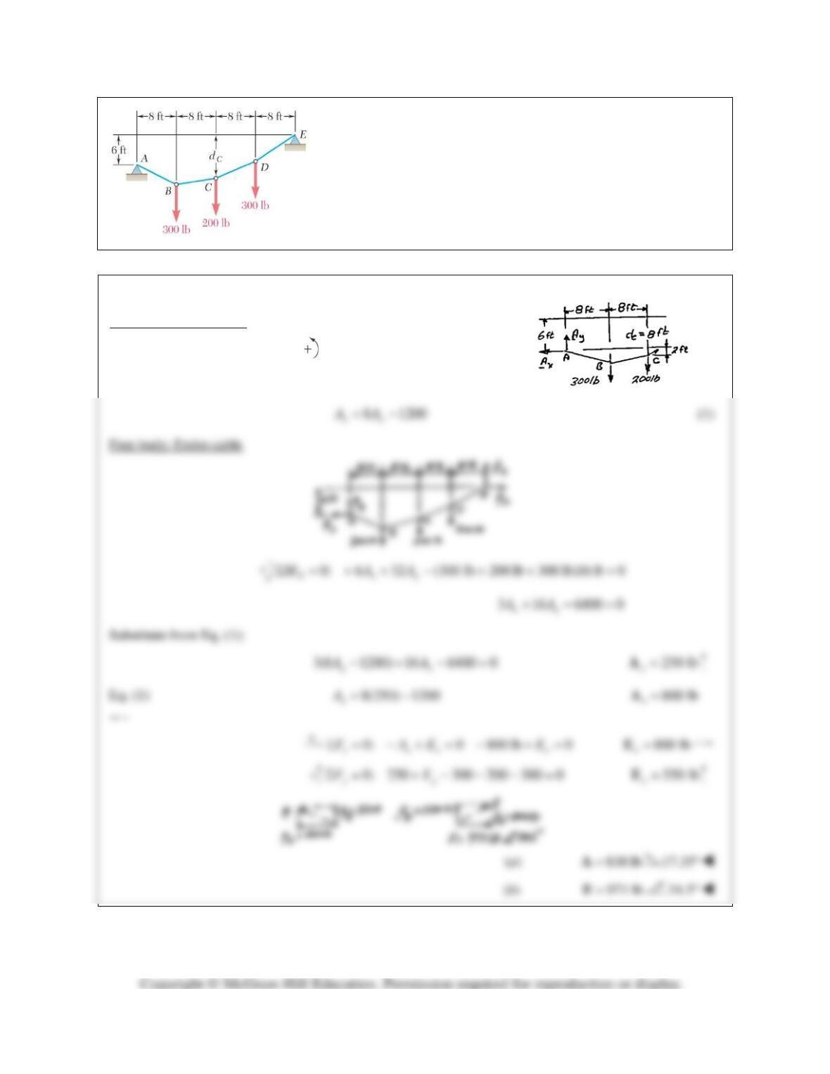
PROBLEM 7.95
If
8 ft,
C
d=
determine (a) the reaction at A, (b) the reaction at E.
SOLUTION
Free body: Portion ABC
0Σ=
C
M
2 16 300(8) 0
xy
AA−+ =
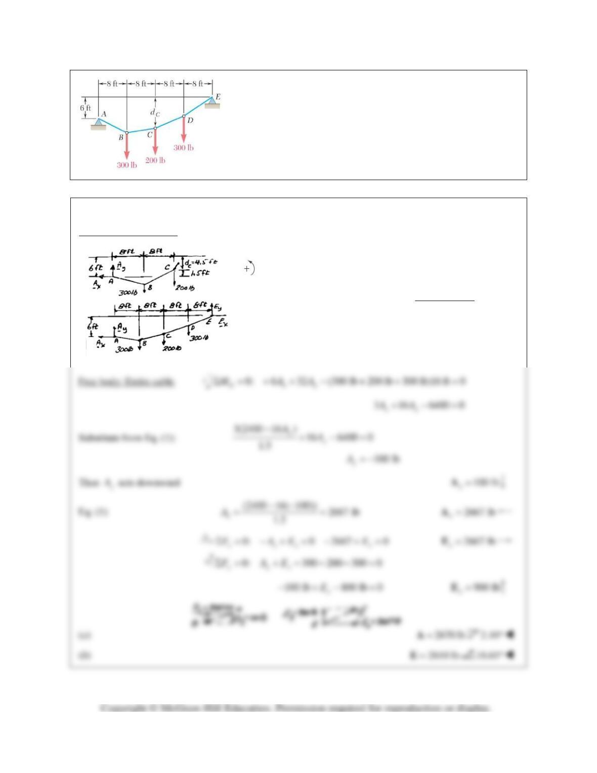
PROBLEM 7.96
If
4.5 ft,
C
d=
determine (a) the reaction at A, (b) the reaction at E.
SOLUTION
Free body: Portion ABC
0: 1.5 16 300 8 0
C xy
M AAΣ = − − + ×=
(2400 16 )
1.5
y
x
A
A−
=
(1)
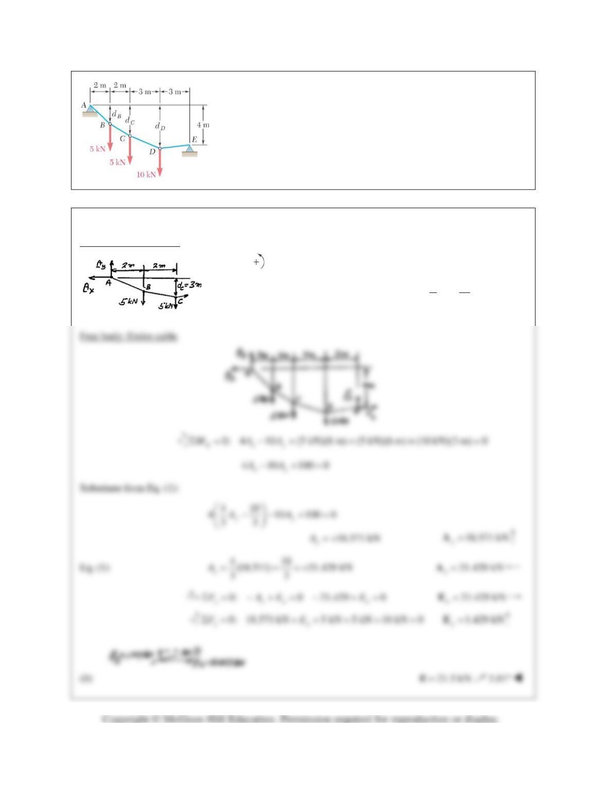
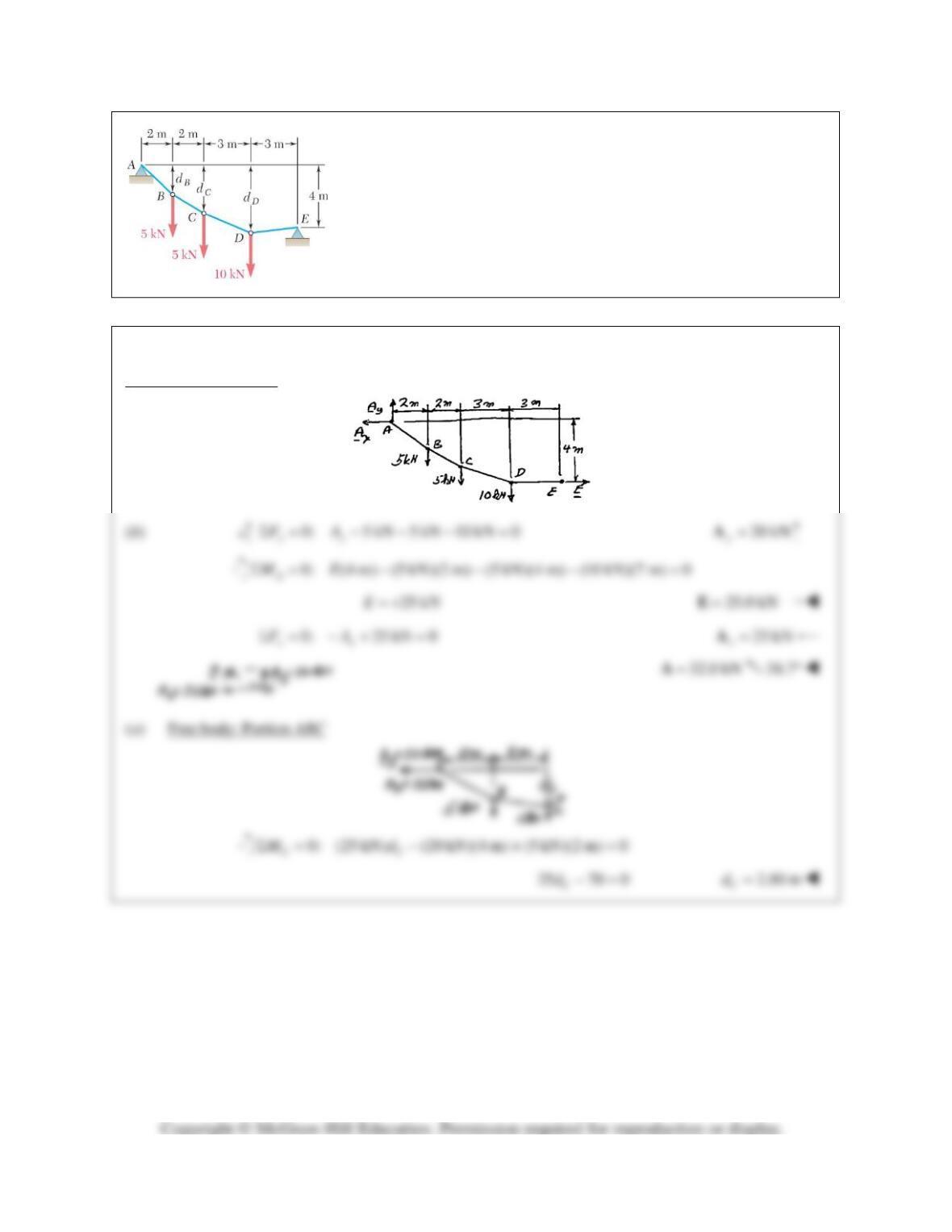
PROBLEM 7.97
Knowing that
3 m,
C
d=
determine (a) the distances
B
d
and
D
d
(b) the
reaction at E.
SOLUTION
Free body: Portion ABC
0: 3 4 (5 kN)(2 m) 0
C xy
M AAΣ= − + =
4 10
33
xy
AA= −
(1)
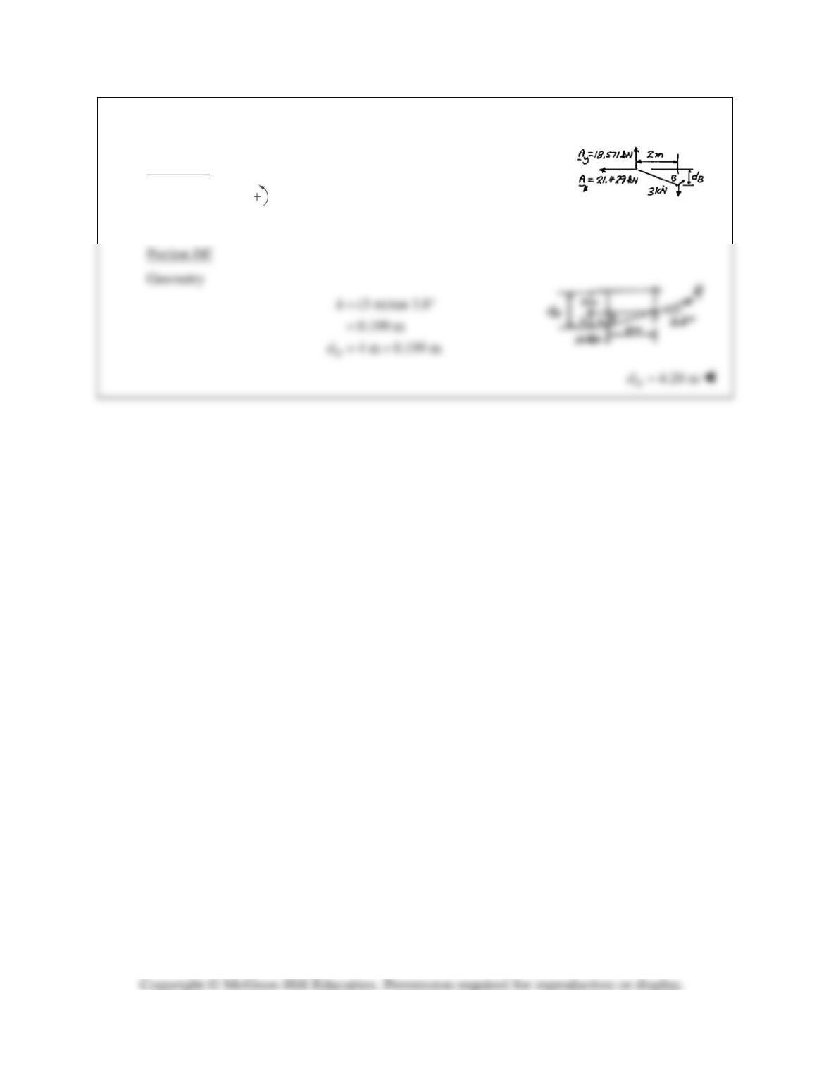
PROBLEM 7.97 (Continued)
(a) Portion AB
0: (18.571 kN)(2 m) (21.429 kN) 0
BB
MdΣ= − =
1.733 m
B
d=
D
PROBLEM 7.98
Determine (a) distance dC for which portion DE of the cable is
horizontal, (b) the corresponding reactions at A and E.
SOLUTION
Free body: Entire cable
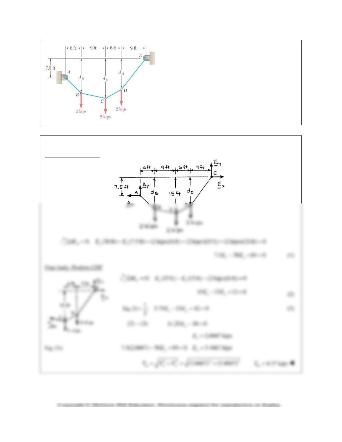
PROBLEM 7.99
If dC= 15 ft, determine (a) the distances dB and dD,
(b) the maximum tension in the cable.
SOLUTION
Free body: Entire cable
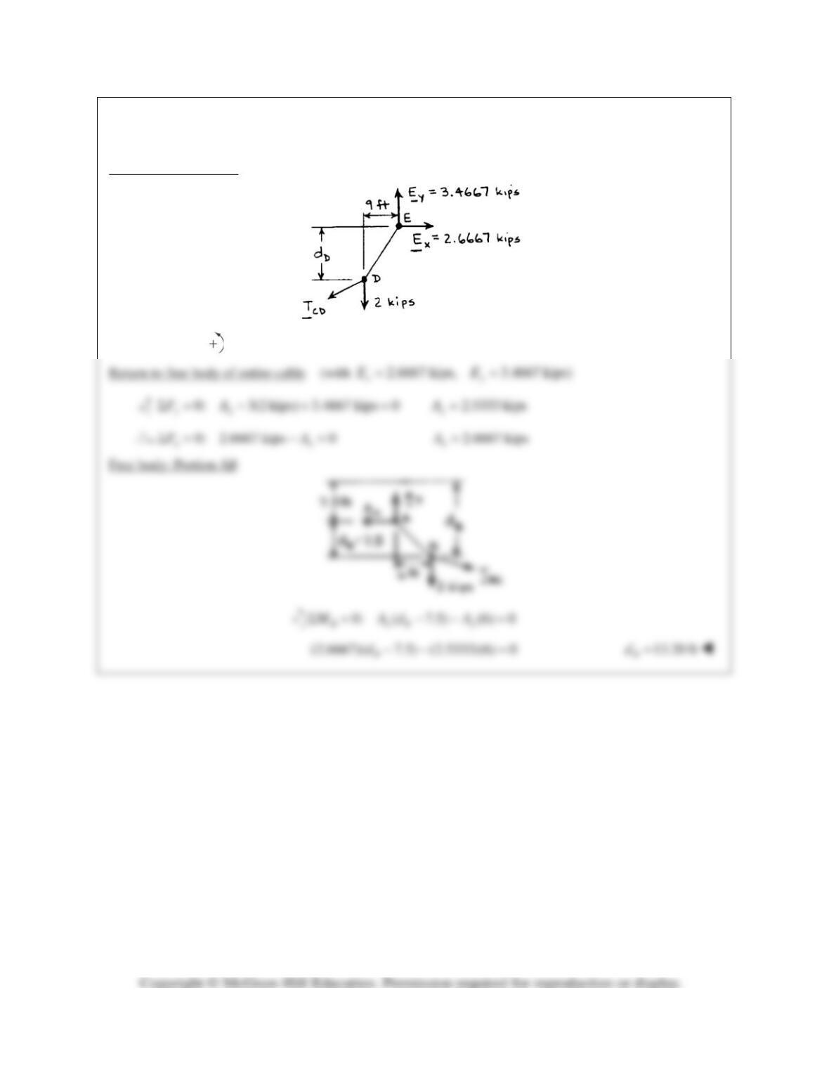
PROBLEM 7.99 (Continued)
Free body: Portion DE
0: (3.4667 kips)(9 ft) (2.6667 kips) 0
DD
MdΣ= − =
11.70 ft
D
d=