PROBLEM 7.54
Solve Problem 7.53 when
60 .
θ
= °
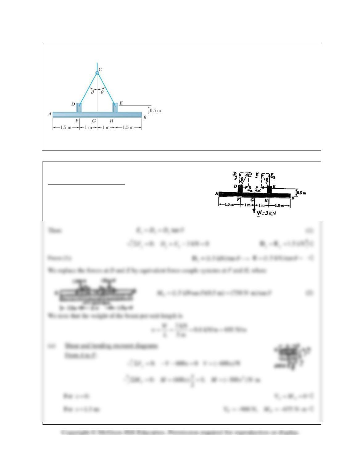
PROBLEM 7.53 Two small channel sections DF and
EH have been welded to the uniform beam AB of weight
W
3 kN=
to form the rigid structural member shown.
This member is being lifted by two cables attached at D
and E. Knowing that
30
θ
= °
and neglecting the weight
of the channel sections, (a) draw the shear and bending-
moment diagrams for beam AB, (b) determine the
maximum absolute values of the shear and bending
moment in the beam.
SOLUTION
Free body: Beam and channels
From symmetry:
yy
ED=
PROBLEM 7.54 (Continued)
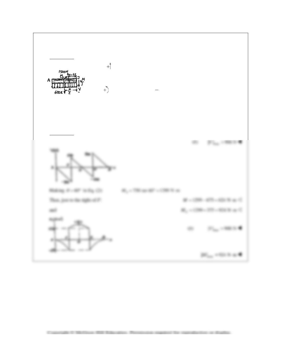
From F to H:
0: 1500 600 0
y
F xVΣ = − −=
(1500 600 ) NVx= −
0
0: (600 ) 1500( 1.5) 0
2
J
x
M Mx x MΣ= + − − −=
2
0300 1500( 1.5) N mMM x x=−+ −⋅
For
1.5 m:x=
0
600 N, ( 675) N m
FF
V MM=+ =−⋅
For
2.5 m:x=
0
0, ( 375) N m
GG
V MM= =−⋅
From G to B, The V and M diagrams will be obtained by symmetry,
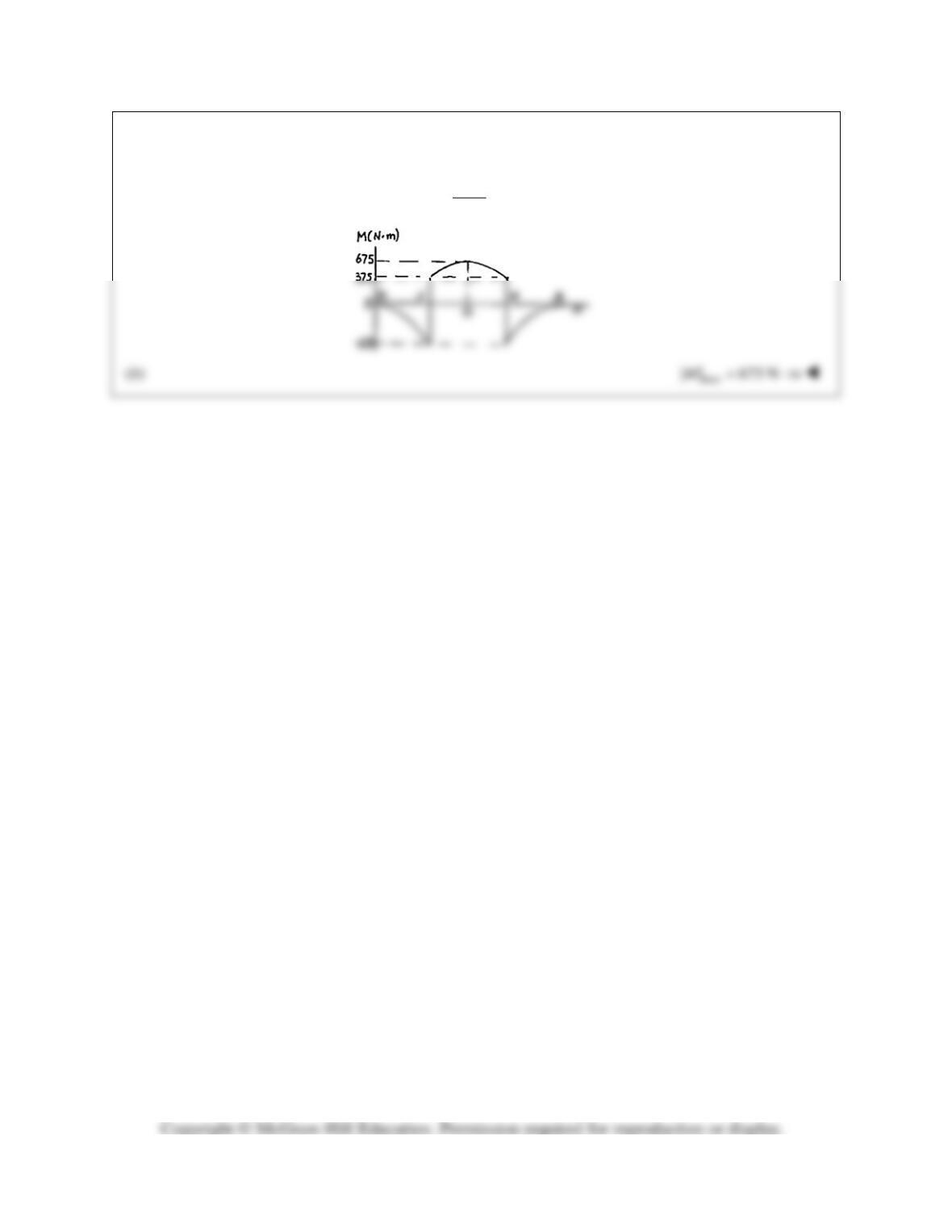
PROBLEM 7.55
For the structural member of Problem 7.53, determine
(a) the angle
θ
for which the maximum absolute value of
the bending moment in beam AB is as small as possible,
(b) the corresponding value of
max
||.M
(Hint: Draw the
bending-moment diagram and then equate the absolute
values of the largest positive and negative bending
moments obtained.)
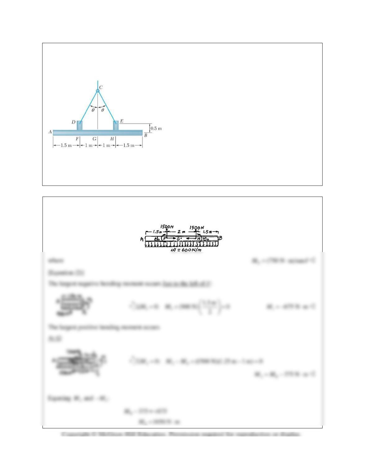
PROBLEM 7.53 Two small channel sections DF and EH
have been welded to the uniform beam AB of weight
W= 3 kN to form the rigid structural member shown. This
member is being lifted by two cables attached at D and E.
Knowing that
θ
= 30° and neglecting the weight of the
channel sections, (a) draw the shear and bending-moment
diagrams for beam AB, (b) determine the maximum absolute
values of the shear and bending moment in the beam.
SOLUTION
See solution of Problem 7.50 for reduction of loading or beam AB to the following:
PROBLEM 7.55 (Continued)
(a) From Equation (2):
1050
tan 1.400
750
θ
= =
54.5
θ
= °
PROBLEM 7.56
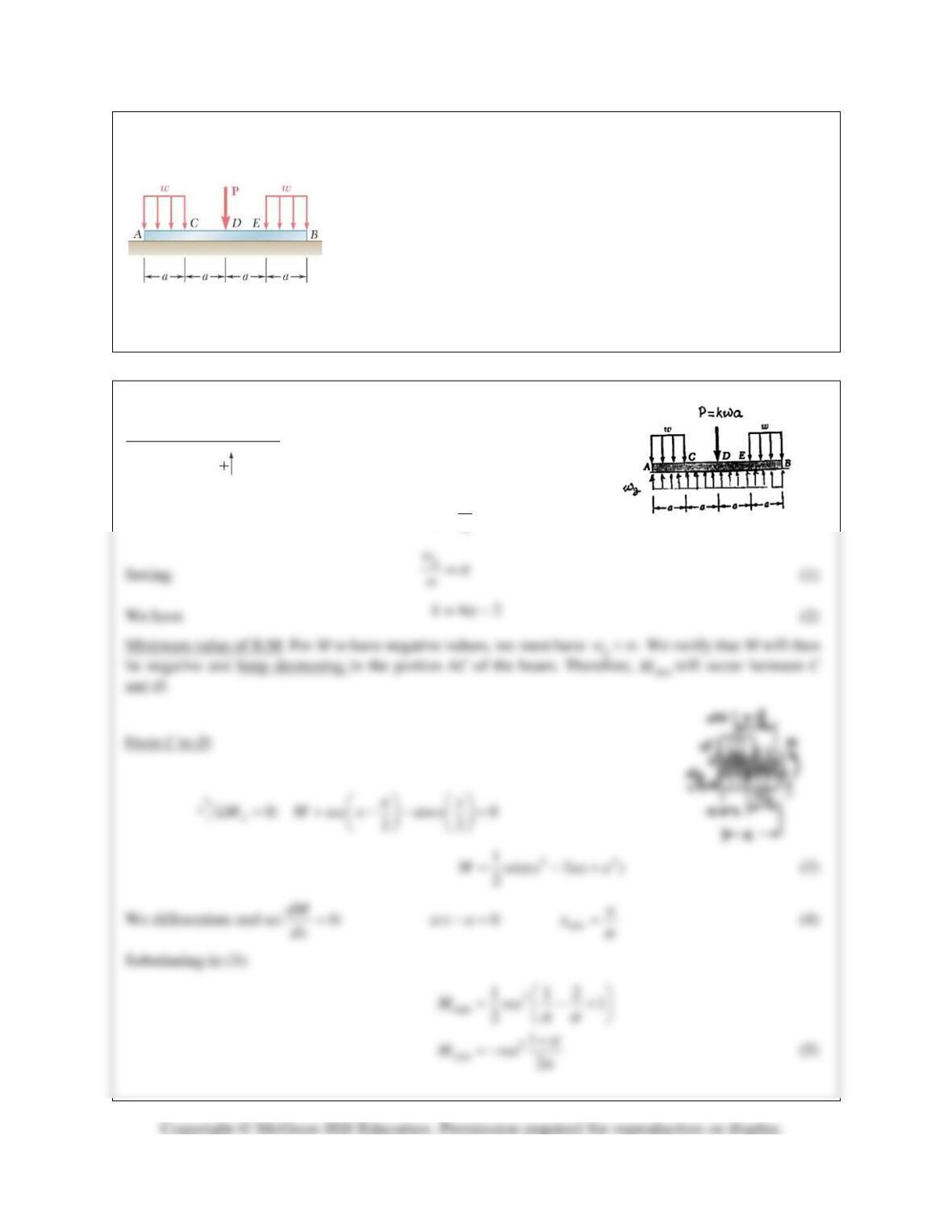
For the beam of Problem 7.43, determine (a) the ratio k=P/wa for which
the maximum absolute value of the bending moment in the beam is as
small as possible, (b) the corresponding value of |M|max. (See hint for
Problem 7.55.)
PROBLEM 7.43 Assuming the upward reaction of the ground on beam
AB to be uniformly distributed and knowing that P =wa, (a) draw the
shear and bending-moment diagrams, (b) determine the maximum
absolute values of the shear and bending moment.
SOLUTION
Free body: Entire beam
0: (4 ) 2 0
yg
F w a wa kwaΣ= − − =
(2 )
4
g
w
wk= +
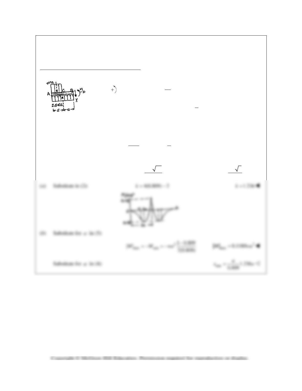
PROBLEM 7.56 (Continued)
Maximum value of bending moment occurs at D
3
0: (2 ) 0
2
DD
a
M M wa wa a
α
Σ= + − =
2
max
3
22
D
M M wa
α
= = −
(6)
Equating
min
M−
and
max :M
22
2
13
2
22
4 2 10
wa wa
αα
α
αα
−
= −
− −=
2 20
8
α
+
=
15
0.809
4
α
+
= =
PROBLEM 7.57
Determine (a) the distance a for which the maximum absolute
value of the bending moment in beam AB is as small as
possible, (b) the corresponding value of Mmax. (See hint for
Prob. 7.55.)
SOLUTION
Tension in cords supporting load:
100 mm
0: 2 80 N 0; 50 mm
40 N
80 N
x
yy
y
y
x
T
FT T
T
T
↑Σ = − = =
=
=
PROBLEM 7.57 (Continued)
0: 0
y
FVΣ= =
( )
22
0: 3.2 N m 40 N 0 40 3.2M M a MaΣ= ⋅+ − = = −
Equating the absolute values of
12
and MM
:
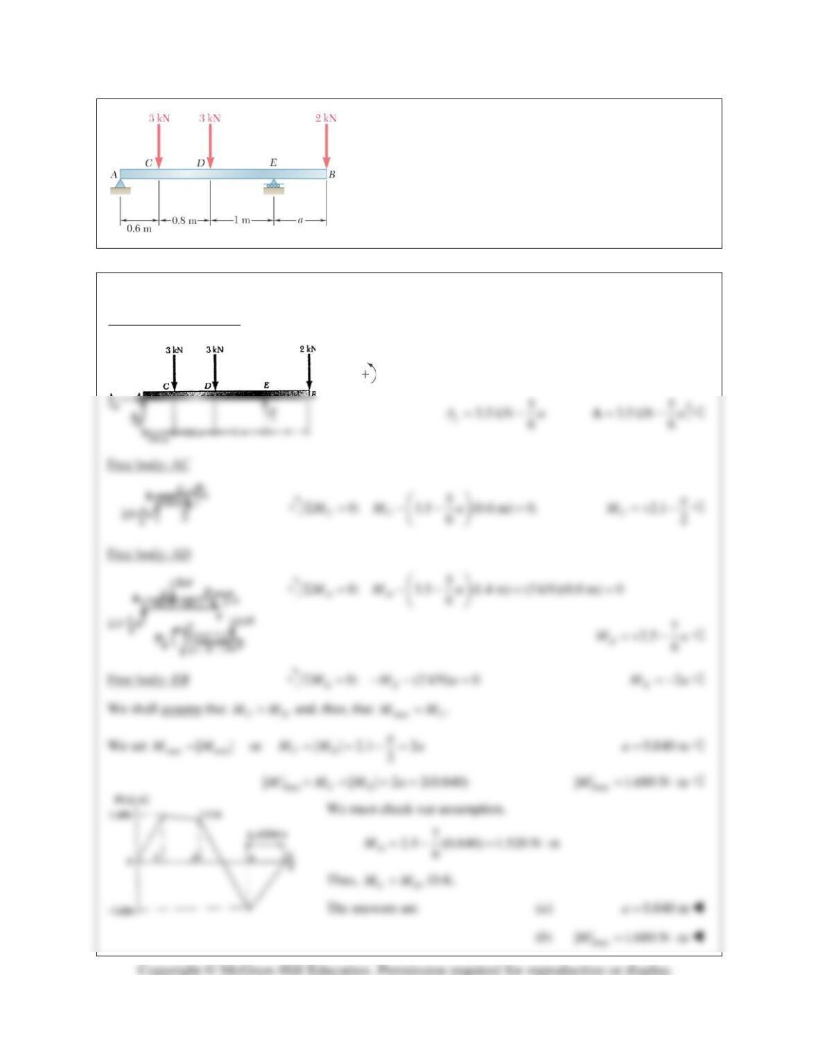
PROBLEM 7.58
For the beam and loading shown, determine (a) the distance a
for which the maximum absolute value of the bending
moment in the beam is as small as possible, (b) the
corresponding value of |M|max. (See hint for Problem 7.55.)
SOLUTION
Free body: Entire beam
0: 0
xx
FAΣ= =
0: (2.4) (3)(1.8) 3(1) (2) 0
Ey
MA aΣ= − + +− =
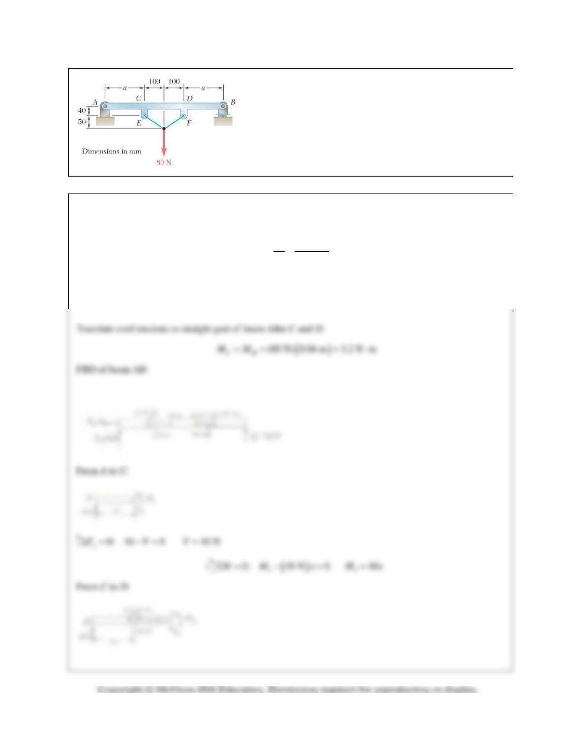
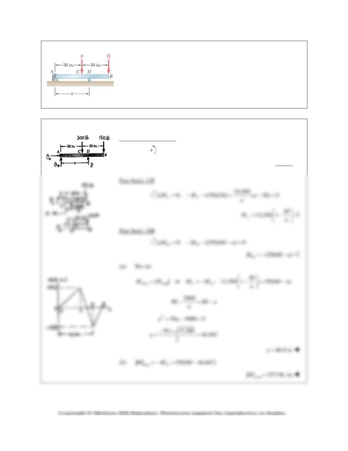
PROBLEM 7.59
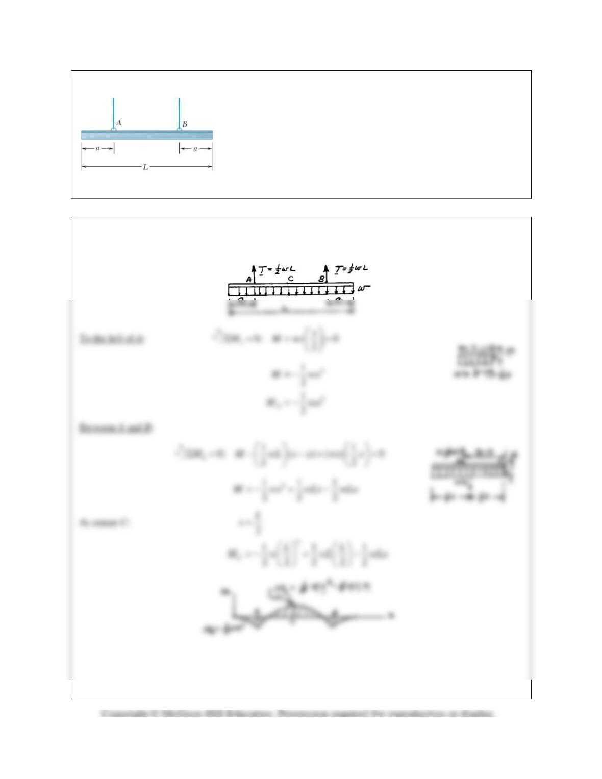
A uniform beam is to be picked up by crane cables attached at A and
B. Determine the distance a from the ends of the beam to the points
where the cables should be attached if the maximum absolute value
of the bending moment in the beam is to be as small as possible.
(Hint: Draw the bending-moment diagram in terms of a, L, and the
weight w per unit length, and then equate the absolute values of the
largest positive and negative bending moments obtained.)
SOLUTION
w= weight per unit length
PROBLEM 7.59 (Continued)
We set
2 2 22
1 11 1 11
| | | |: 2 82 282
AC
M M wa wL wLa wa wL wLa= −=− +=−
22
0.25 0a La L+− =
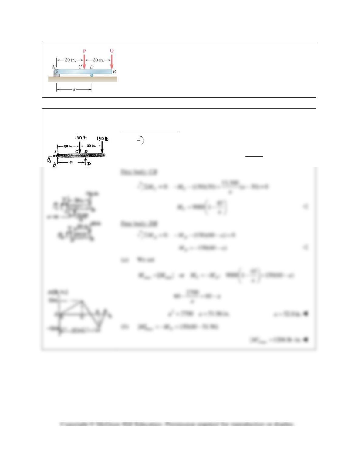
PROBLEM 7.60
Knowing that P =Q= 150 lb, determine (a) the distance a for which the
maximum absolute value of the bending moment in beam AB is as small
as possible, (b) the corresponding value of
max
|| .M
(See hint for Problem
7.55.)
SOLUTION
Free body: Entire beam
0: (150)(30) (150)(60) 0
A
M DaΣ= − − =
13,500
Da
=
PROBLEM 7.61
Solve Problem 7.60 assuming that P = 300 lb and Q= 150lb.
PROBLEM 7.60 Knowing that P =Q= 150 lb, determine (a) the distance
a for which the maximum absolute value of the bending moment in beam
AB is as small as possible, (b) the corresponding value of
max
|| .M
(See
hint for Problem 7.55.)
SOLUTION
Free body: Entire beam
0: (300)(30) (150)(60) 0
A
M DaΣ= − − =
18,000
Da
=
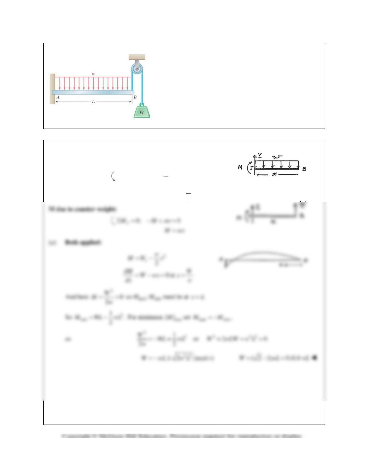
PROBLEM 7.62*
In order to reduce the bending moment in the cantilever beam
AB, a cable and counterweight are permanently attached at end
B. Determine the magnitude of the counterweight for which the
maximum absolute value of the bending moment in the beam
is as small as possible and the corresponding value of
max
|| .M
Consider (a) the case when the distributed load is permanently
applied to the beam, (b) the more general case when the
distributed load may either be applied or removed.
SOLUTION
M due to distributed load:
2
0: 0
2
1
2
J
x
M M wx
M wx
Σ = −− =
= −
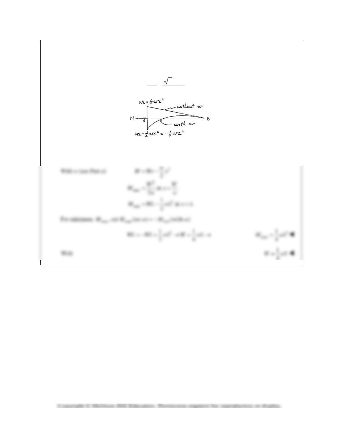
PROBLEM 7.62* (Continued)
(b) w may be removed
22
2
max
( 2 1)
22
W
M wL
w
−
= =
2
max 0.0858M wL=
Without w,
max at
M Wx
M WL A
=
=
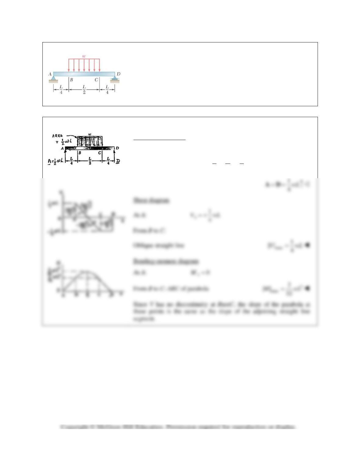
PROBLEM 7.63
Using the method of Section 7.6, solve Problem 7.29.
PROBLEM 7.29 For the beam and loading shown, (a) draw the shear
and bending-moment diagrams, (b) determine the maximum absolute
values of the shear and bending moment.
SOLUTION
Reactions at A and D
Because of the symmetry of the supports and loading.
11
224
L
A D w wL
= = =
PROBLEM 7.64
Using the method of Section 7.6, solve Problem 7.30.
PROBLEM 7.30 For the beam and loading shown, (a) draw the shear
and bending-moment diagrams, (b) determine the maximum absolute
values of the shear and bending moment.
SOLUTION
Free body: Entire beam
0
1
0: ( )( ) 0
2
y
F B wLΣ= − =
0
1
2wL=B
PROBLEM 7.65
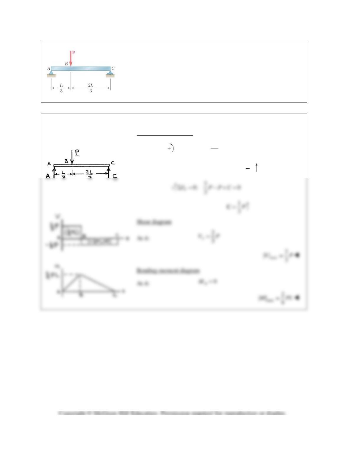
Using the method of Section 7.6, solve Problem 7.31.
PROBLEM 7.31 For the beam and loading shown, (a) draw the shear
and bending-moment diagrams, (b) determine the maximum absolute
values of the shear and bending moment.
SOLUTION
Free body: Entire beam
2
0: ( ) 0
3
C
L
M P AL
Σ= − =
2
3P=A
PROBLEM 7.66
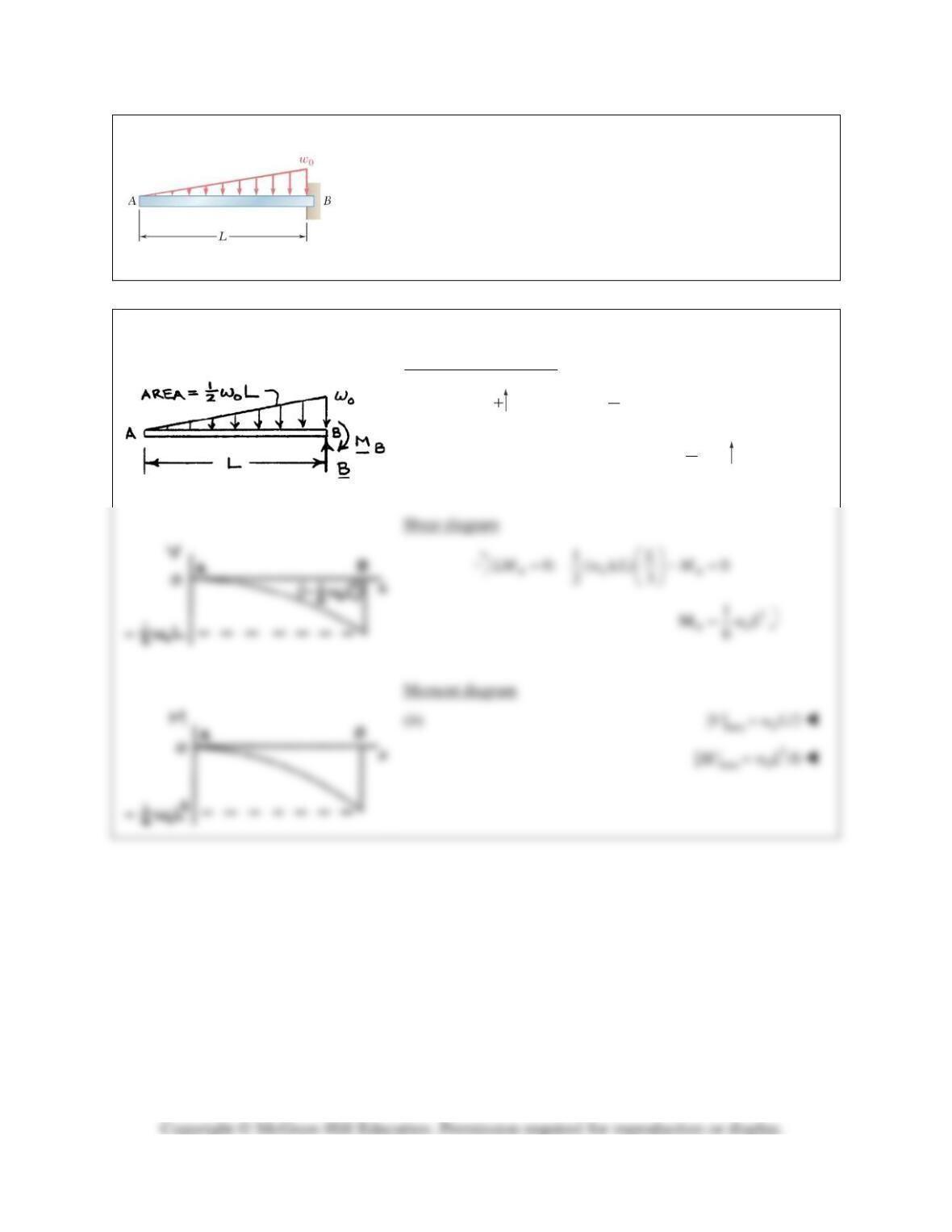
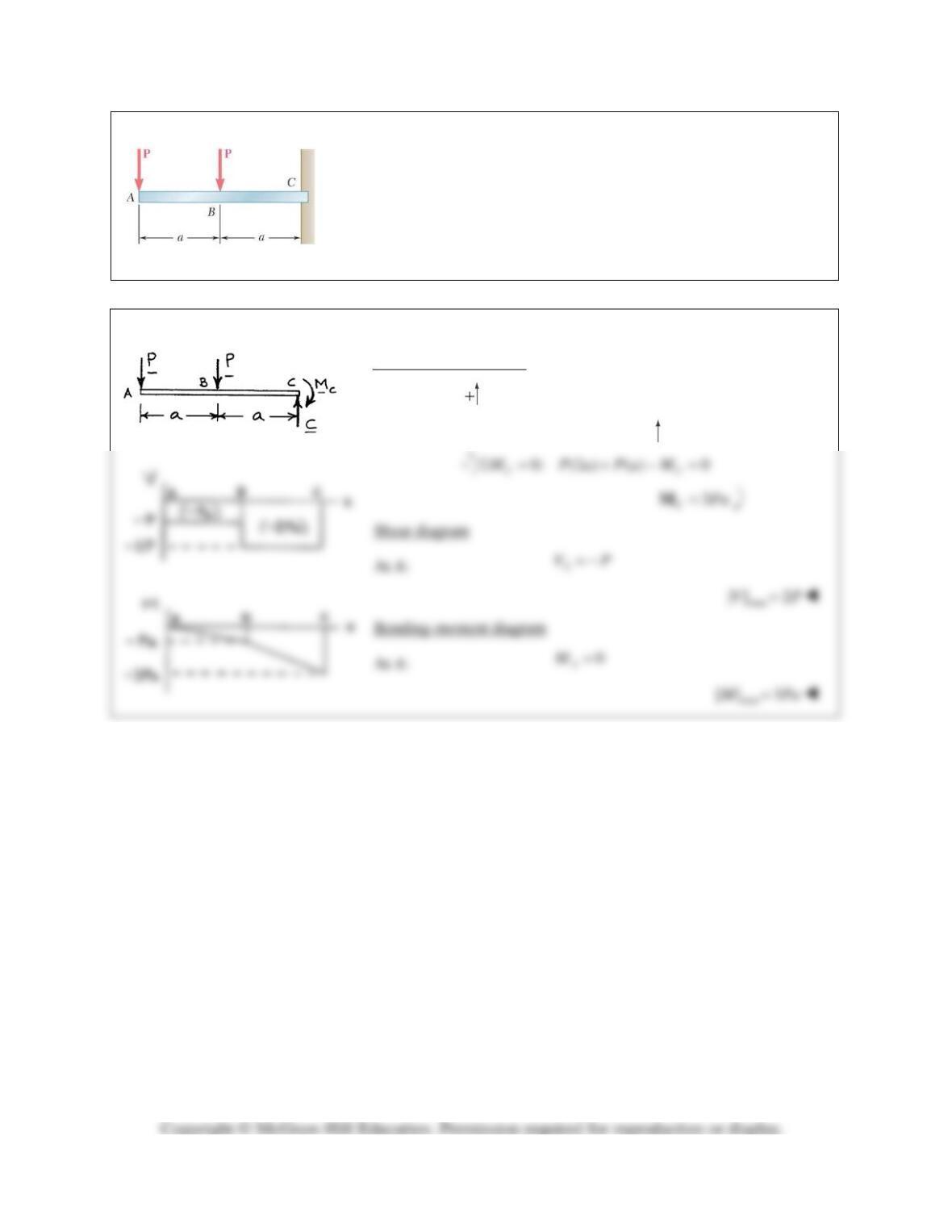
Using the method of Section 7.6, solve Problem 7.32.
PROBLEM 7.32 For the beam and loading shown, (a) draw the shear
and bending-moment diagrams, (b) determine the maximum absolute
values of the shear and bending moment.
SOLUTION
Free body: Entire beam
0: 0
y
F CPPΣ = −−=
2P=C
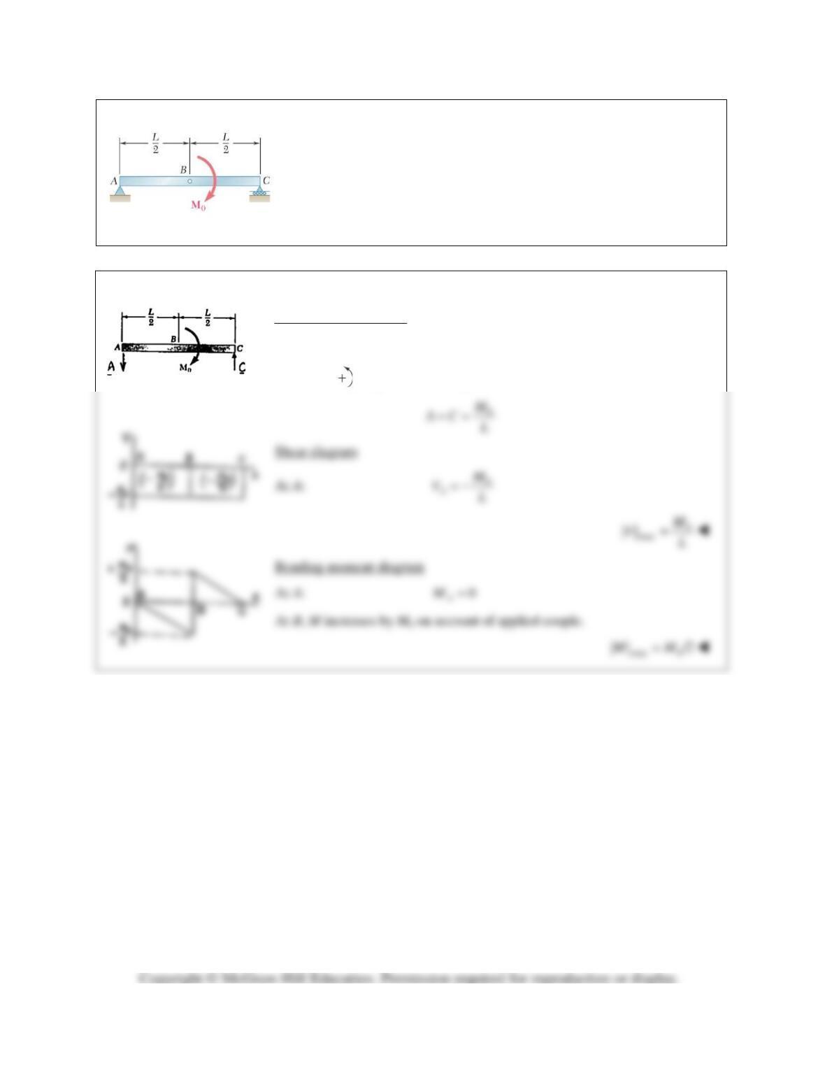
PROBLEM 7.67
Using the method of Section 7.6, solve Problem 7.33.
PROBLEM 7.33 For the beam and loading shown, (a) draw the shear and
bending-moment diagrams, (b) determine the maximum absolute values
of the shear and bending moment.
SOLUTION
Free body: Entire beam
0:
y
F ACΣ= =
0
0: 0
C
M Al MΣ= −=