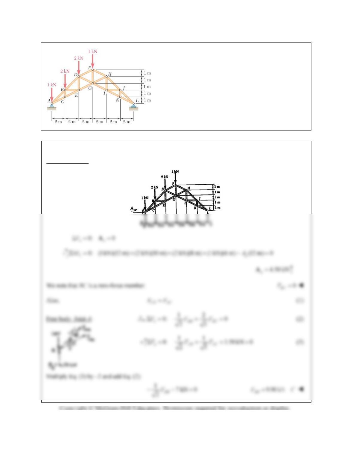
PROBLEM 6.21
Determine the force in each of the members located to the
left of FG for the scissors roof truss shown. State whether
each member is in tension or compression.
SOLUTION
Free Body: Truss:
PROBLEM 6.21 (Continued)
Subtract Eq. (3) from Eq. (2):
13.50 kN 0 7.826 kN
5
AC AC
FF
7.83 kN
AC
FT
From Eq. (1): 7.826 kN
CE AC
FF 7.83 kN
CE
FT
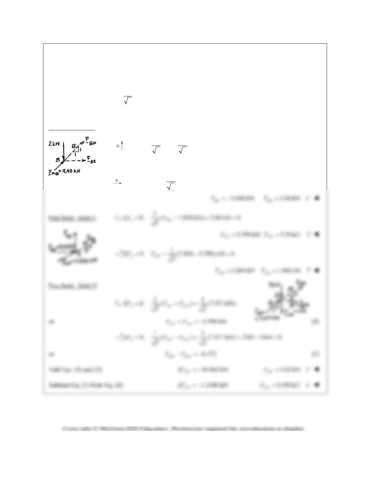
Free body: Joint B:
11
0: (9.90kN) 2kN 0
22
yBD
FF
7.071 kN
BD
F 7.07 kN
BD
FC
1
0: (9.90 7.071) kN 0
2
xBE
FF
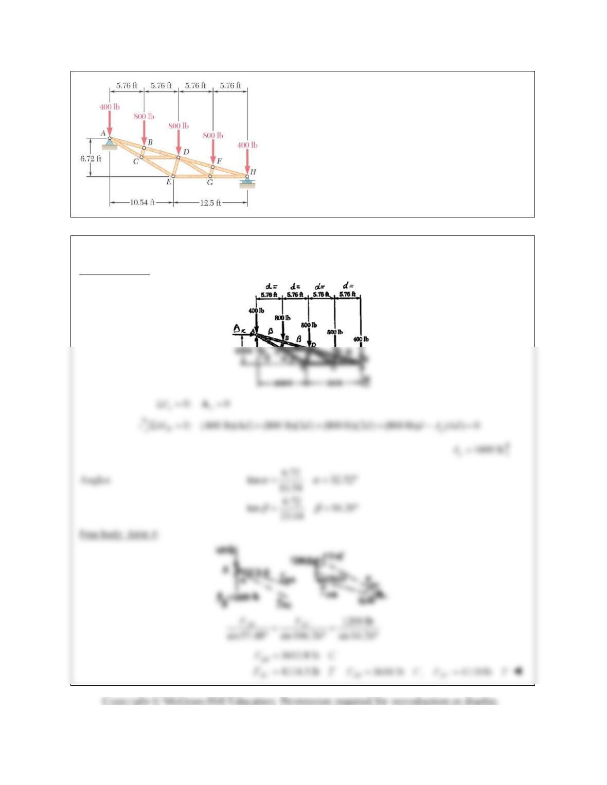
PROBLEM 6.22
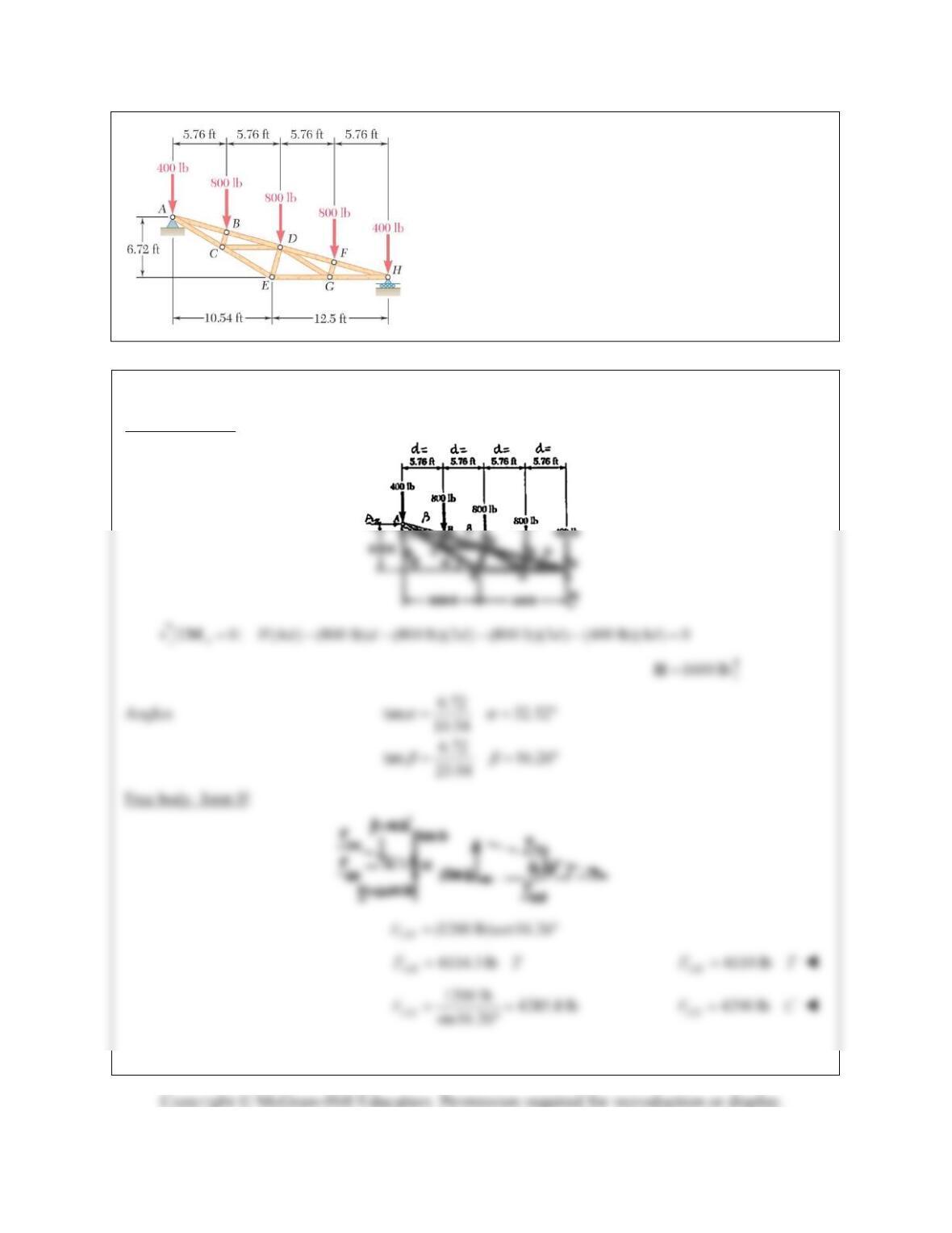
Determine the force in member DE and in each of the
members located to the left of DE for the inverted Howe
roof truss shown. State whether each member is in tension
or compression.
SOLUTION
Free body: Truss:
PROBLEM 6.22 (Continued)
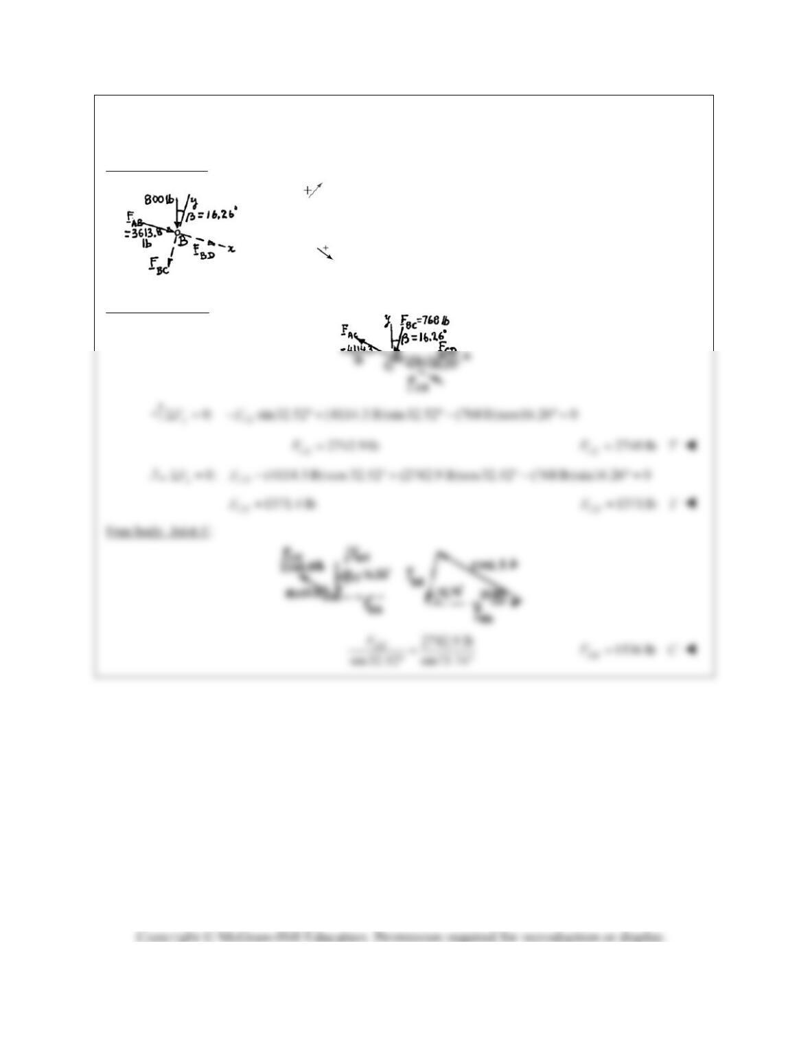
Free body: Joint B:
0: (800 lb)cos16.26 0
yBC
FF
768.0 lb 768 lb
BC BC
FFC
0: 3613.8 lb (800 lb) sin16.26° 0
xBD
FF
3837.8 lb
BD
F 3840 lb
BD
FC
Free body: Joint C:
PROBLEM 6.23
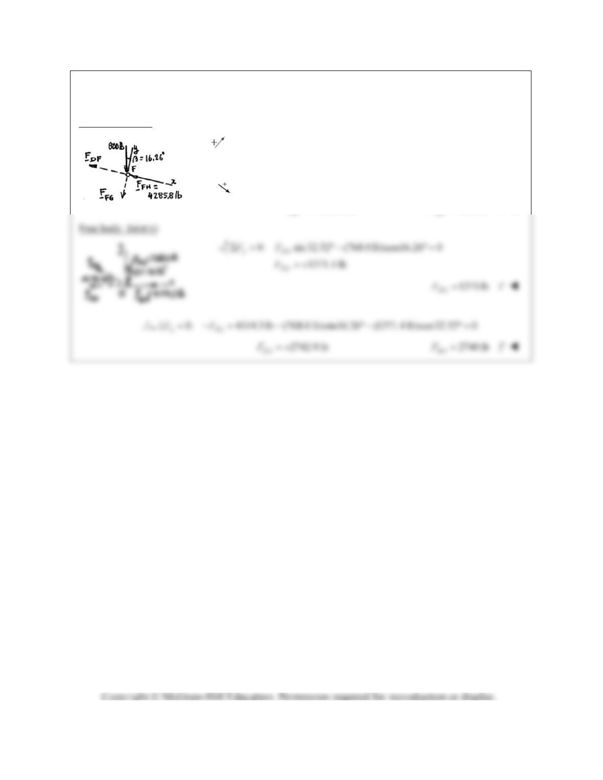
Determine the force in each of the members located to the
right of DE for the inverted Howe roof truss shown. State
whether each member is in tension or compression.
SOLUTION
Free body: Truss
PROBLEM 6.23 (Continued)
Free body Joint F:
0: (800 lb) cos16.26 0
yFG
FF
768.0 lb
FG
F
768 lb
FG
FC
0: 4285.8 lb (800 lb) sin 16.26° 0
xDF
FF
4061.8 lb
DF
F 4060 lb
DF
FC
PROBLEM 6.24
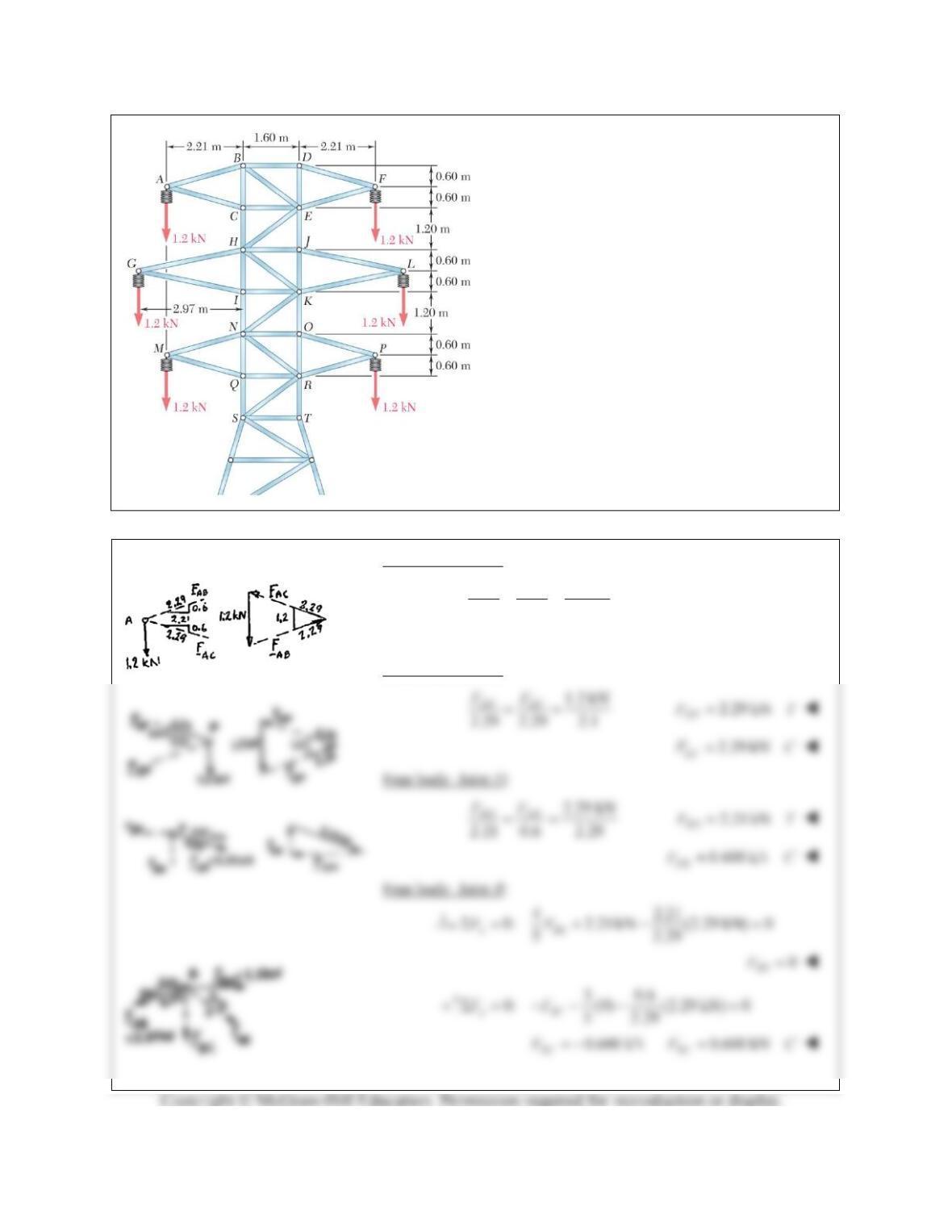
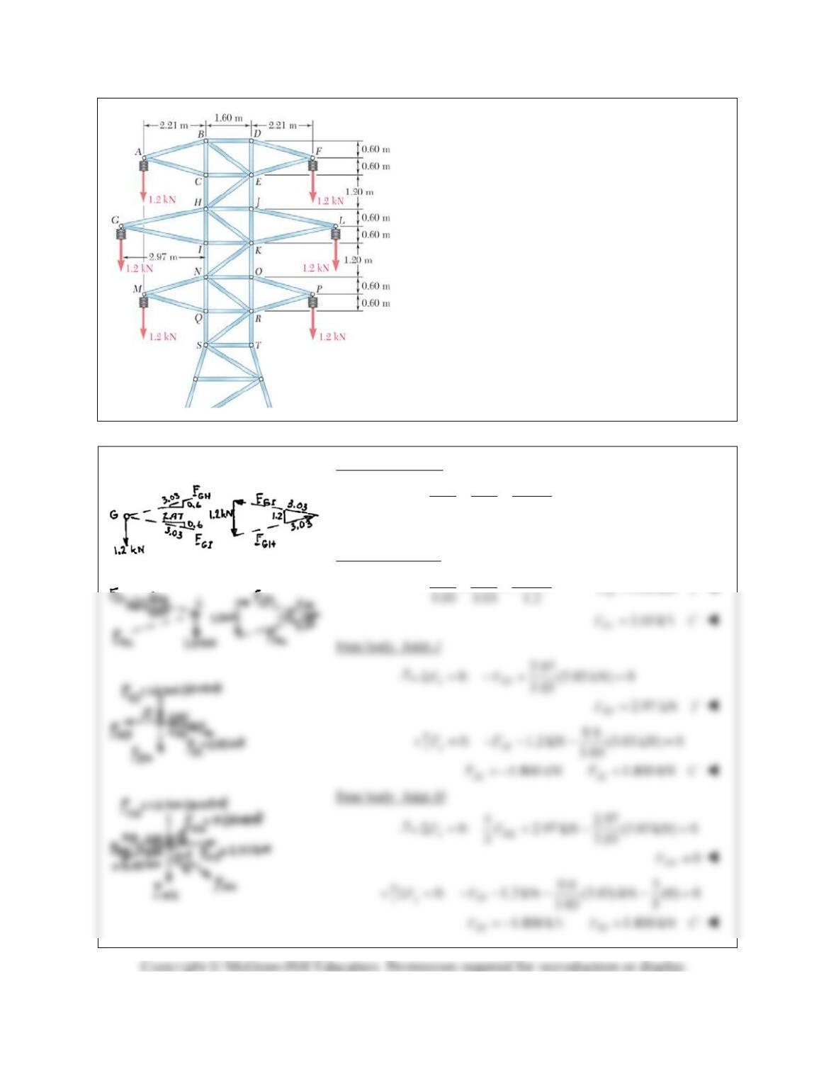
The portion of truss shown represents the upper
part of a power transmission line tower. For the
given loading, determine the force in each of the
members located above HJ. State whether each
member is in tension or compression.
SOLUTION
Free body: Joint A:
1.2 kN
2.29 2.29 1.2
AC
AB
F
F
2.29 kN
AB
FT
2.29 kN
AC
FC
Free body: Joint F:
PROBLEM 6.24 (Continued)
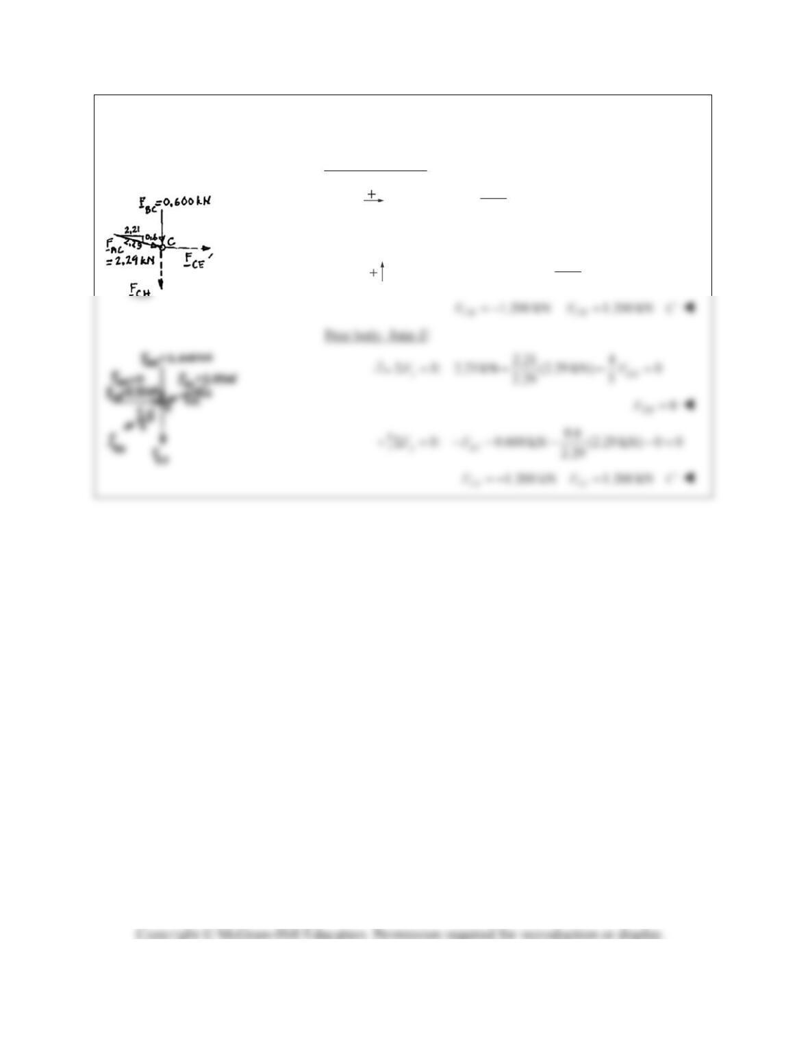
Free body: Joint C:
2.21
0: (2.29 kN) 0
2.29
xCE
FF
2.21 kN
CE
F 2.21 kN
CE
FC
0.6
0: 0.600 kN (2.29 kN) 0
2.29
yCH
FF
PROBLEM 6.25
For the tower and loading of Problem 6.24 and
knowing that F
CH
F
EJ
1.2 kN C and F
EH
0,
determine the force in member HJ and in each of
the members located between HJ and NO. State
whether each member is in tension or
compression.
PROBLEM 6.24 The portion of truss shown
represents the upper part of a power transmission
line tower. For the given loading, determine the
force in each of the members located above HJ.
State whether each member is in tension or
compression.
SOLUTION
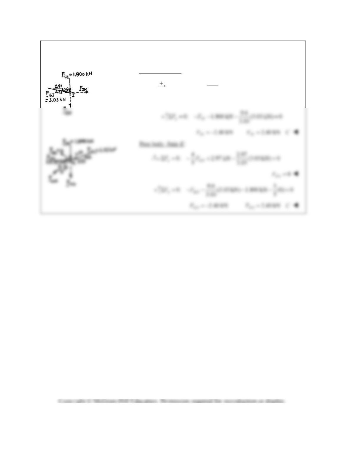
Free body: Joint G:
1.2 kN
3.03 3.03 1.2
GH GI
FF
3.03 kN
GH
FT
3.03 kN
GI
FC
Free body: Joint L:
1.2 kN
JL KL
FF 3.03 kN
FT
PROBLEM 6.25 (Continued)
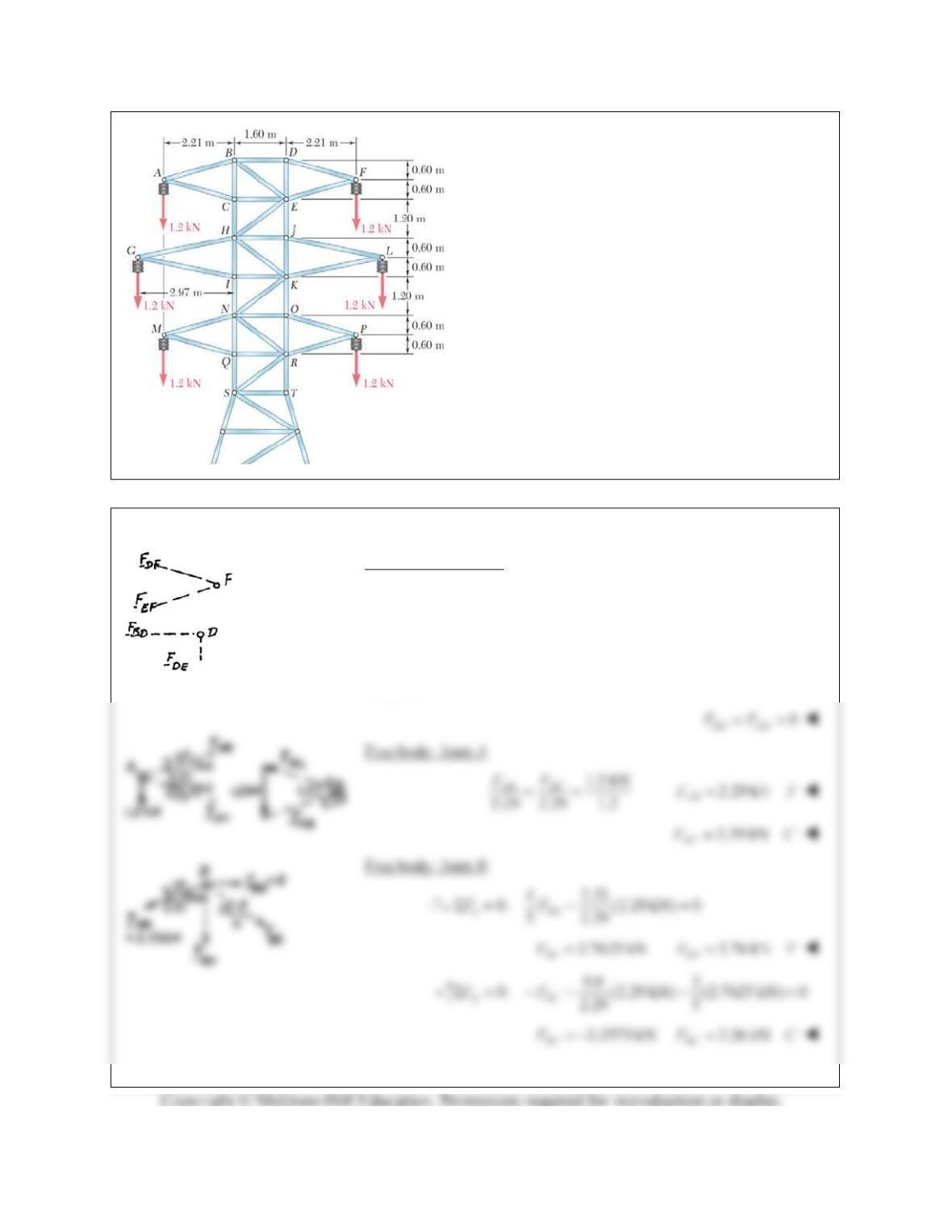
Free body: Joint I:
2.97
0: (3.03 kN) 0
3.03
xIK
FF
2.97 kN
IK
F 2.97 kN
IK
FC
PROBLEM 6.26
Solve Problem 6.24 assuming that the cables
hanging from the right side of the tower have
fallen to the ground.
PROBLEM 6.24 The portion of truss shown
represents the upper part of a power transmission
line tower. For the given loading, determine the
force in each of the members located above HJ.
State whether each member is in tension or
compression.
SOLUTION
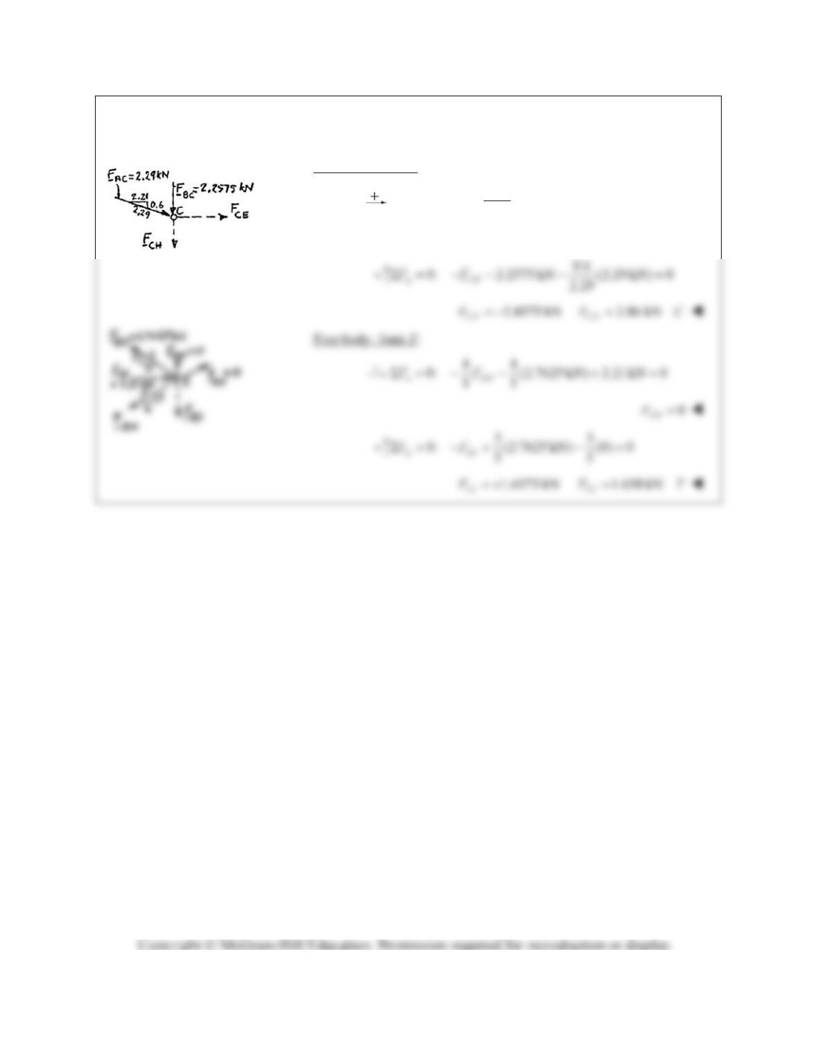
Zero-Force Members:
Considering joint F, we note that DF and EF are zero-force
members:
0
DF EF
FF
Considering next joint D, we note that BD and DE are zero-force
members:
PROBLEM 6.26 (Continued)
Free body: Joint C:
2.21
0: (2.29 kN) 0
2.29
xCE
FF
2.21 kN
CE
FC
PROBLEM 6.27
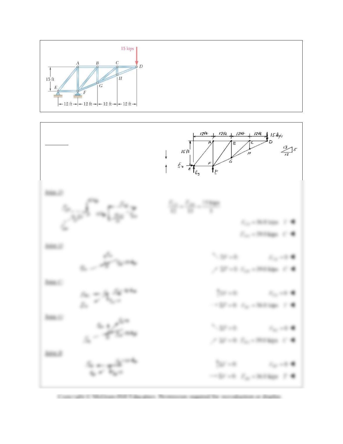
Determine the force in each member of the truss shown.
State whether each member is in tension or compression.
SOLUTION
Reactions: 0:
x
F 0
x
E
0:
F
M
45 kips
y
E
0:
y
F
60 kipsF

PROBLEM 6.27 (Continued)
Joint A:
22
12 15 19.21 ftAE
36 kips
tan 38.7
AF
F
45.0 kips
AF
FC
PROBLEM 6.28
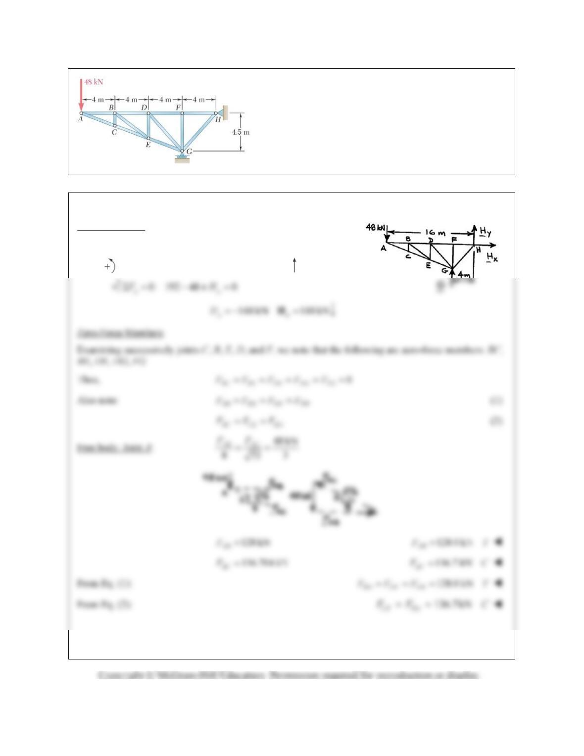
Determine the force in each member of the truss shown.
State whether each member is in tension or compression.
SOLUTION
Free body: Truss
0: 0
xx
F H
0: 48(16) (4) 0 192 kN
H
MG G
PROBLEM 6.28 (Continued)
Free body: Joint H
144 kN
9
145
GH
F
192.7 kN
GH
FC
PROBLEM 6.29
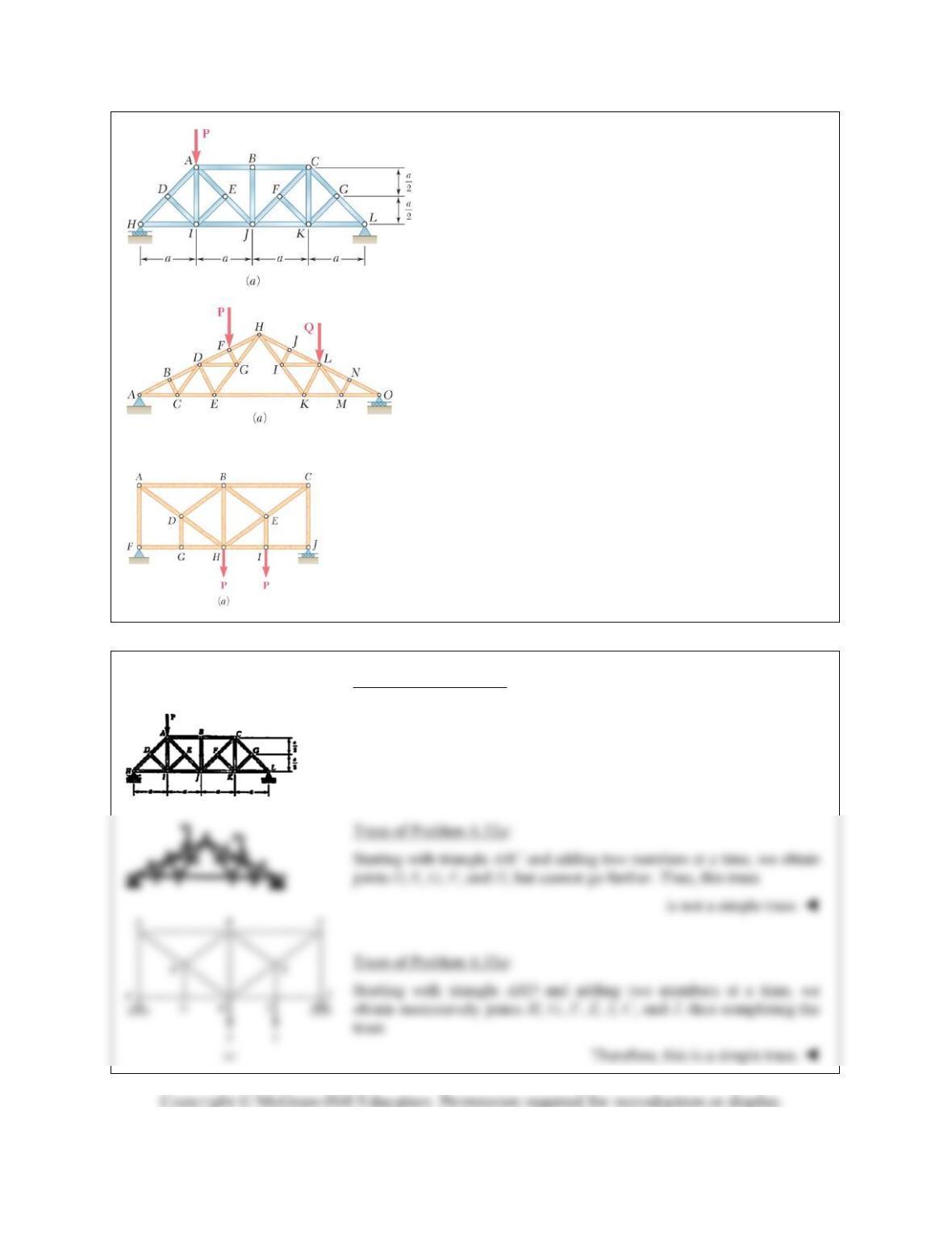
Determine whether the trusses of Problems 6.31a,
6.32a, and 6.33a are simple trusses.
SOLUTION
Truss of Problem 6.31a:
Starting with triangle HDI and adding two members at a time, we
obtain successively joints A, E, J, and B, but cannot go further. Thus,
this truss
is not a simple truss.
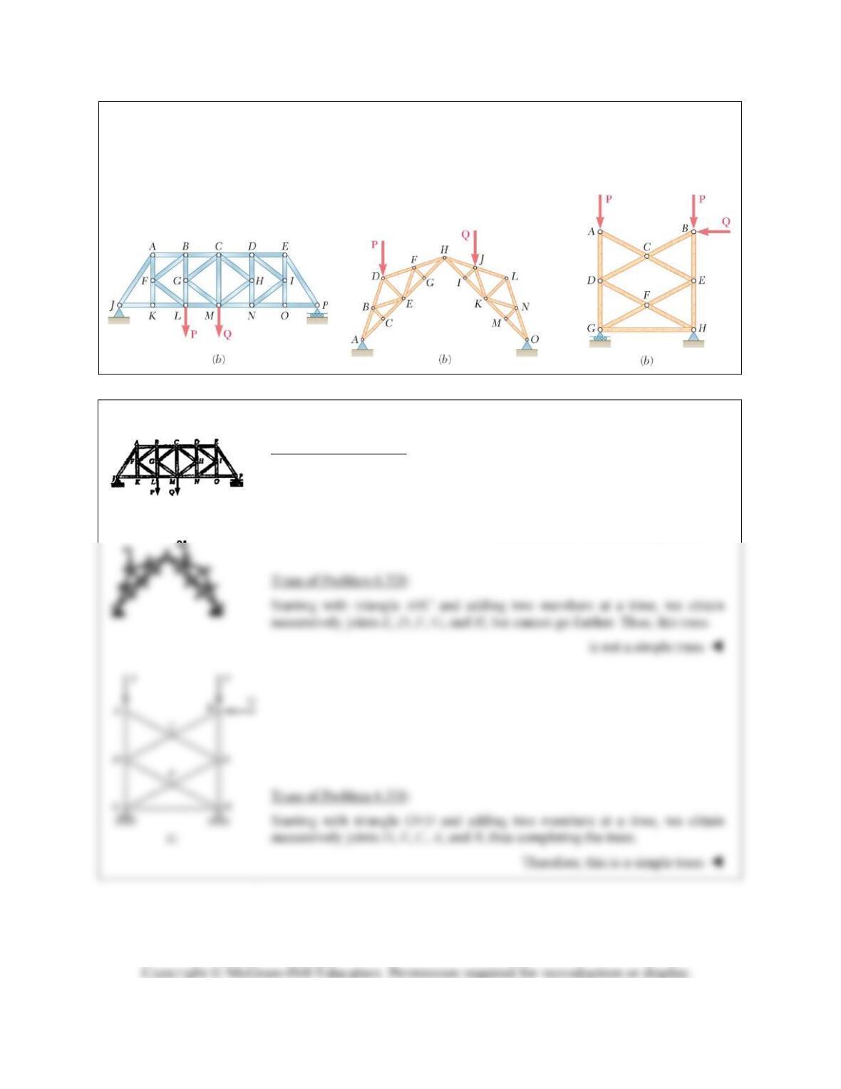
PROBLEM 6.30
Determine whether the trusses of Problems 6.31b, 6.32b, and 6.33b are simple trusses.
SOLUTION
Truss of Problem 6.31b:
Starting with triangle CGM and adding two members at a time, we obtain
successively joints B, L, F, A, K, J, then H, D, N, I, E, O, and P, thus
completing the truss.
Therefore, this truss is a simple truss.
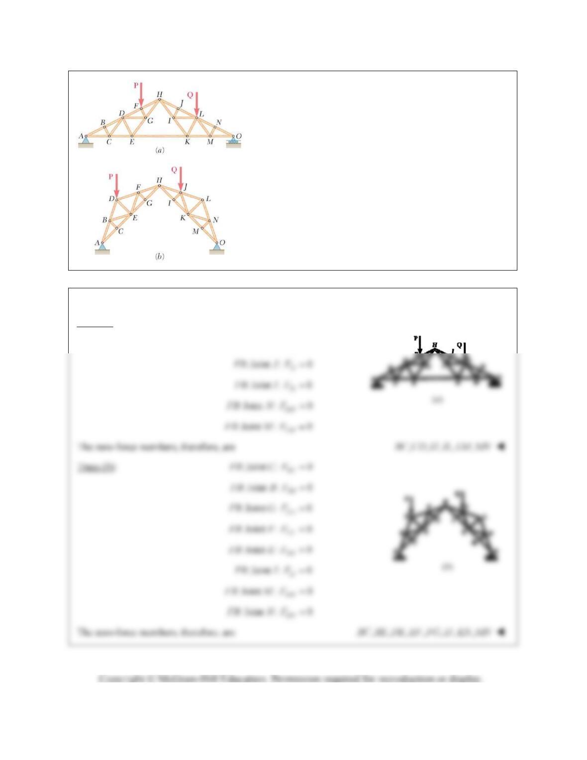
PROBLEM 6.31
For the given loading, determine the zero-force members in
each of the two trusses shown.
SOLUTION
Truss (a): : Joint : 0
BC
FB B F
: Joint : 0
CD
FB C F
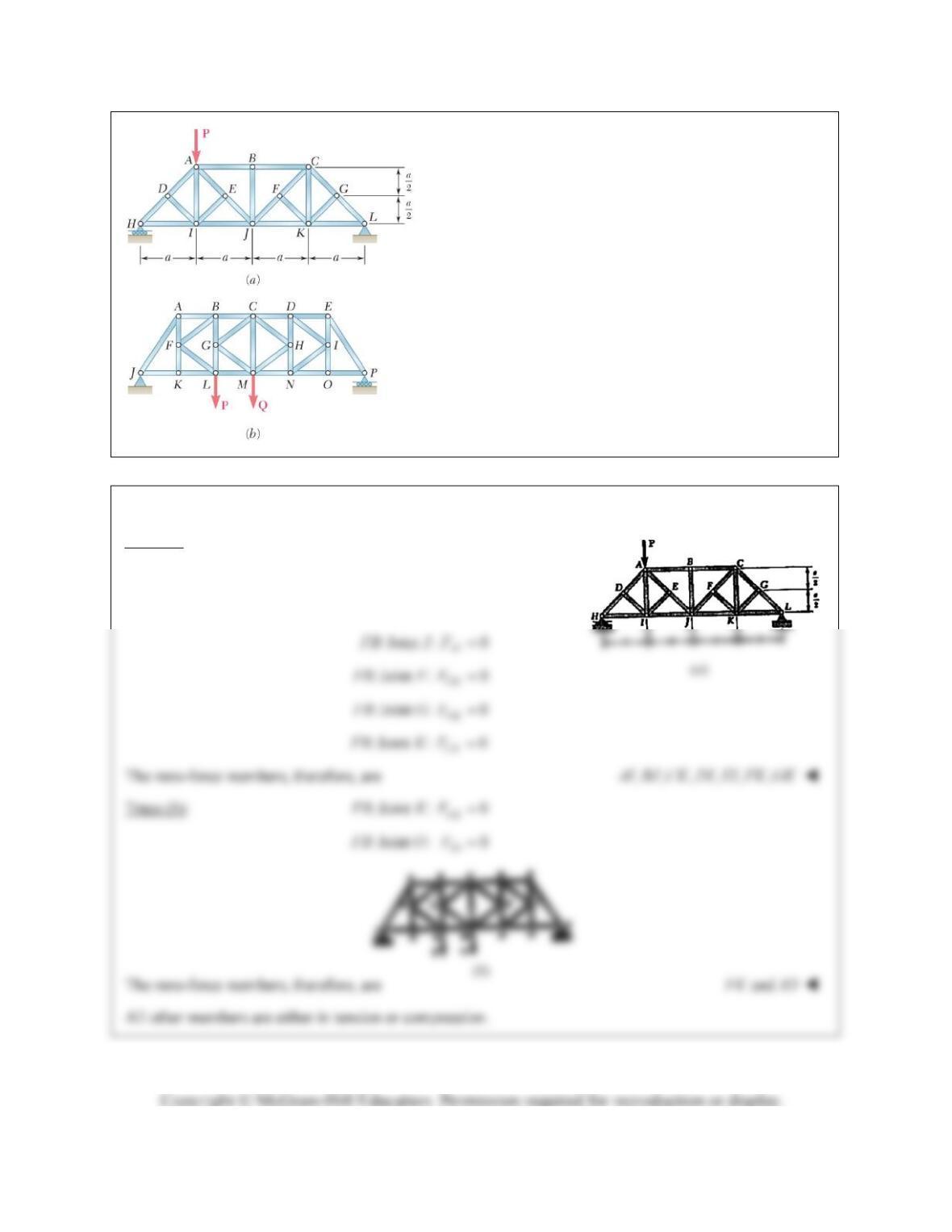
PROBLEM 6.32
For the given loading, determine the zero-force members
in each of the two trusses shown.
SOLUTION
Truss (a): : Joint : 0
BJ
FB B F
: Joint : 0
DI
FB D F
: Joint : 0
EI
FB E F