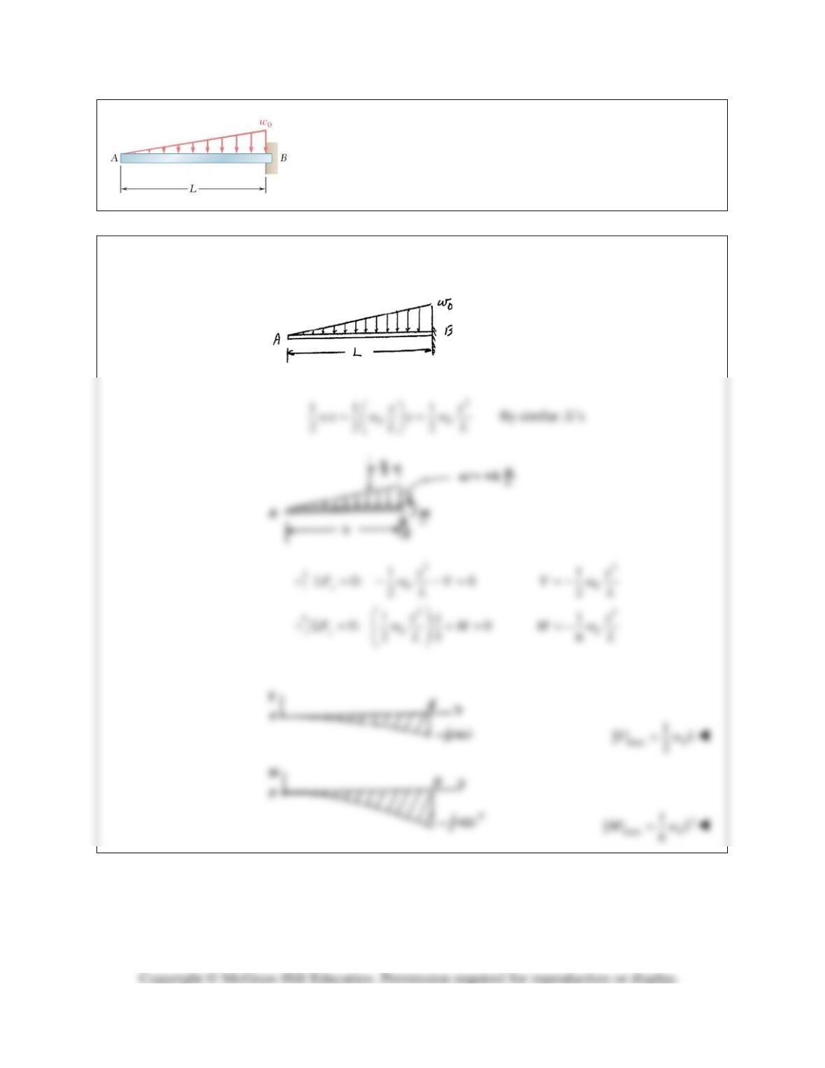
PROBLEM 7.30
For the beam and loading shown, (a) draw the shear and bending-
moment diagrams, (b) determine the maximum absolute values of the
shear and bending moment.
SOLUTION
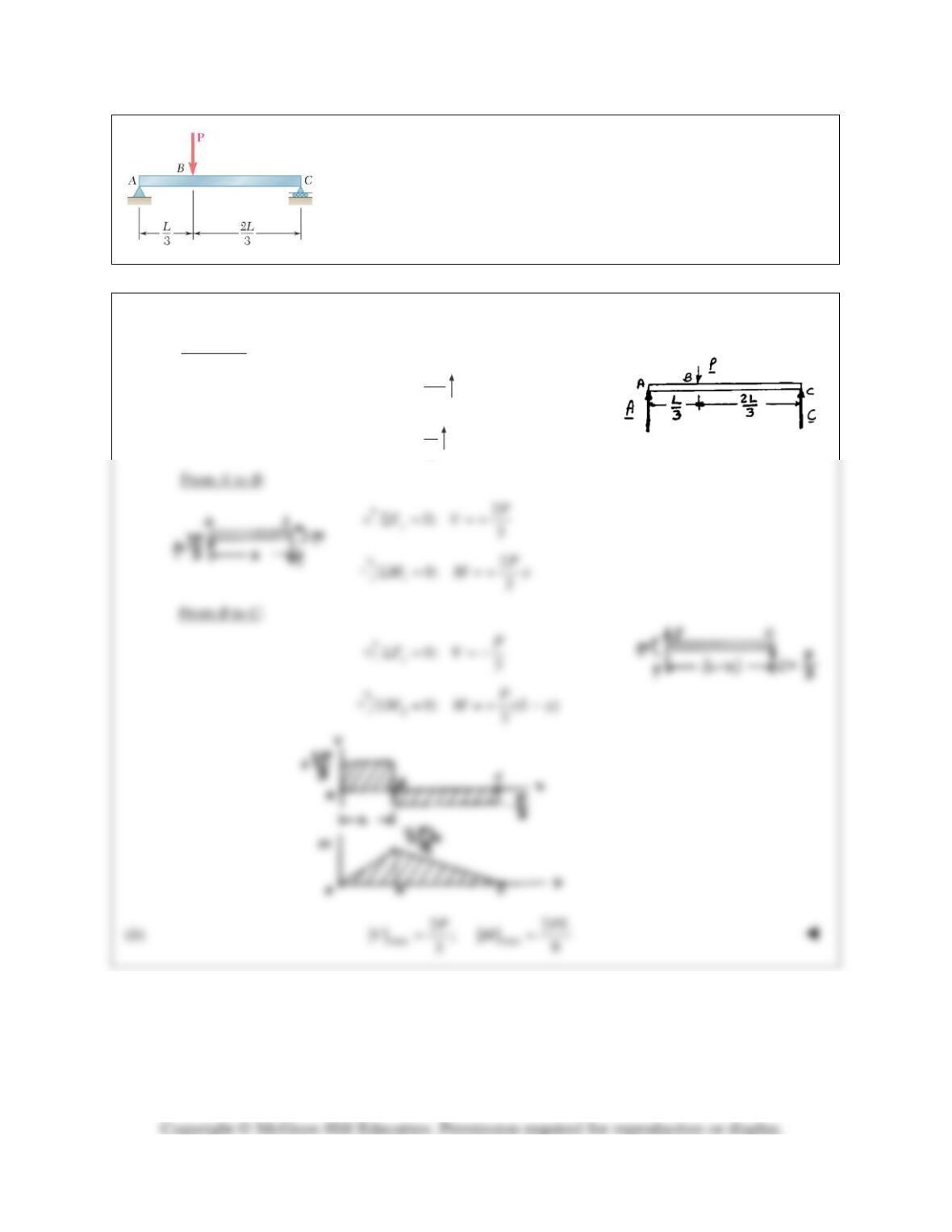
PROBLEM 7.31
For the beam and loading shown, (a) draw the shear and bending-moment
diagrams, (b) determine the maximum absolute values of the shear and
bending moment.
SOLUTION
(a) Reactions:
2
3
P
=A
3
P
=C
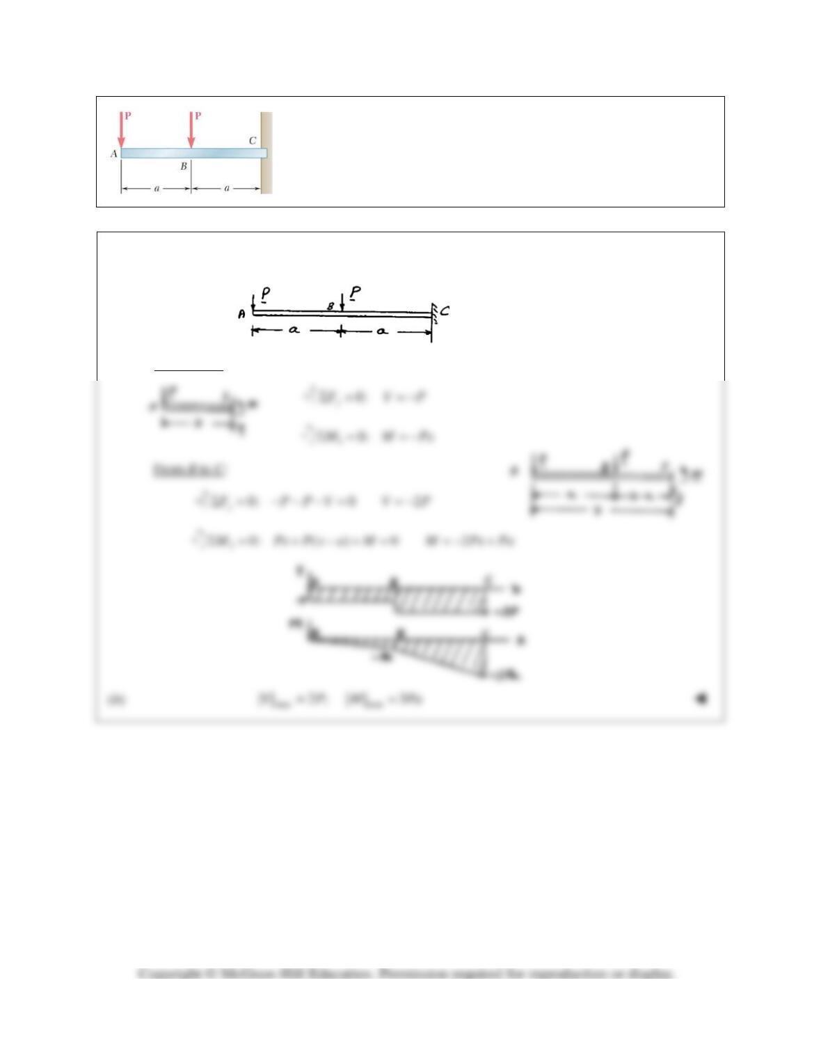
PROBLEM 7.32
For the beam and loading shown, (a) draw the shear and bending-
moment diagrams, (b) determine the maximum absolute values of the
shear and bending moment.
SOLUTION
(a)
From A to B:
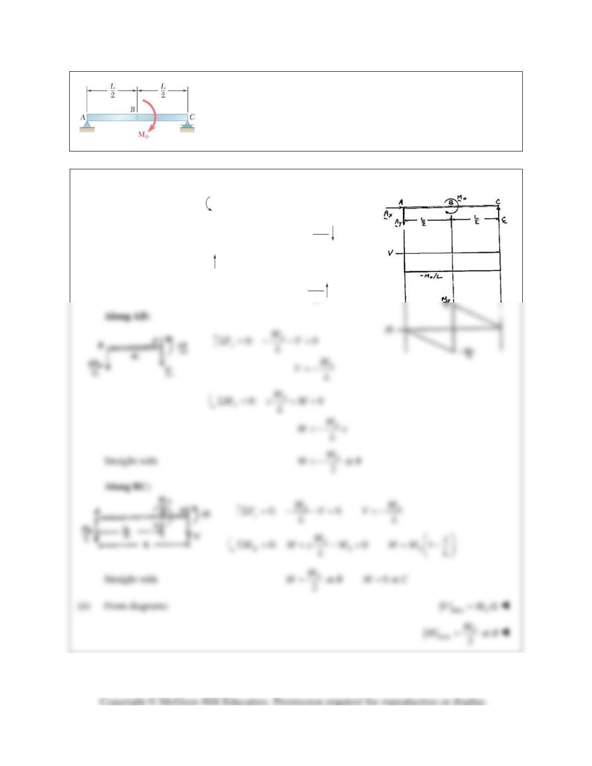
PROBLEM 7.33
For the beam and loading shown, (a) draw the shear and bending-moment
diagrams, (b) determine the maximum absolute values of the shear and
bending moment.
SOLUTION
(a) FBD Beam:
0
0: 0
Cy
M LA MΣ= −=
0
y
M
L
=A
0: 0
yy
F ACΣ= − +=
0
M
L
=C
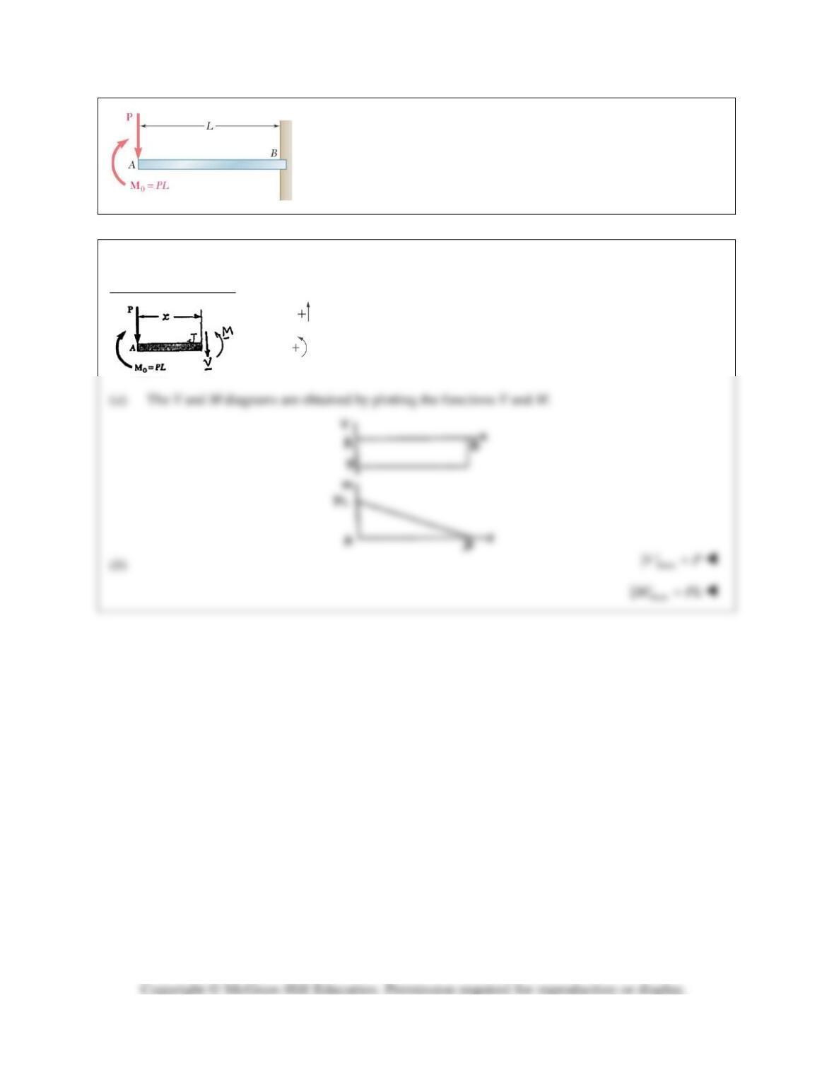
PROBLEM 7.34
For the beam and loading shown, (a) draw the shear and bending-
moment diagrams, (b) determine the maximum absolute values of the
shear and bending moment.
SOLUTION
Free body: Portion AJ
0: 0
y
F PVΣ = −− =
VP= −
0: 0Σ = +− =
Jx
M M P PL
()M PL x= −
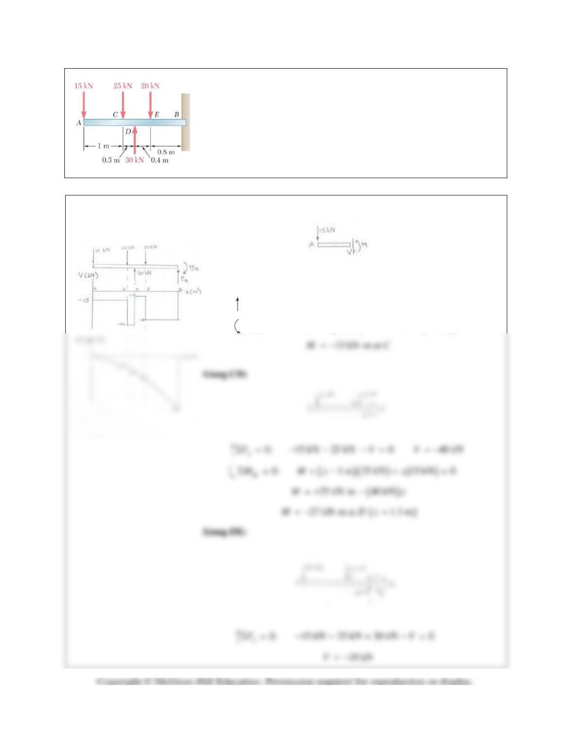
PROBLEM 7.35
For the beam and loading shown, (a) draw the shear and bending-moment
diagrams, (b) determine the maximum absolute values of the shear and
bending moment.
SOLUTION
(a)
Along AC:
0: 15 kN 0 15 kN
y
F VVΣ= − −= =−
( ) ( )
0: 15 kN 0 15 kN
J
M Mx M xΣ= + = =
PROBLEM 7.35
(Continued)
( ) ( )( )
11
0: 30 kN 0.3 m 25 kN
L
M Mx xΣ= − + +
( )( )
1
1.3 m 15 kN 0x++ =
PROBLEM 7.36
For the beam and loading shown, (a) draw the shear and bending-
moment diagrams, (b) determine the maximum absolute values of
the shear and bending moment.
SOLUTION
Free body: Entire beam
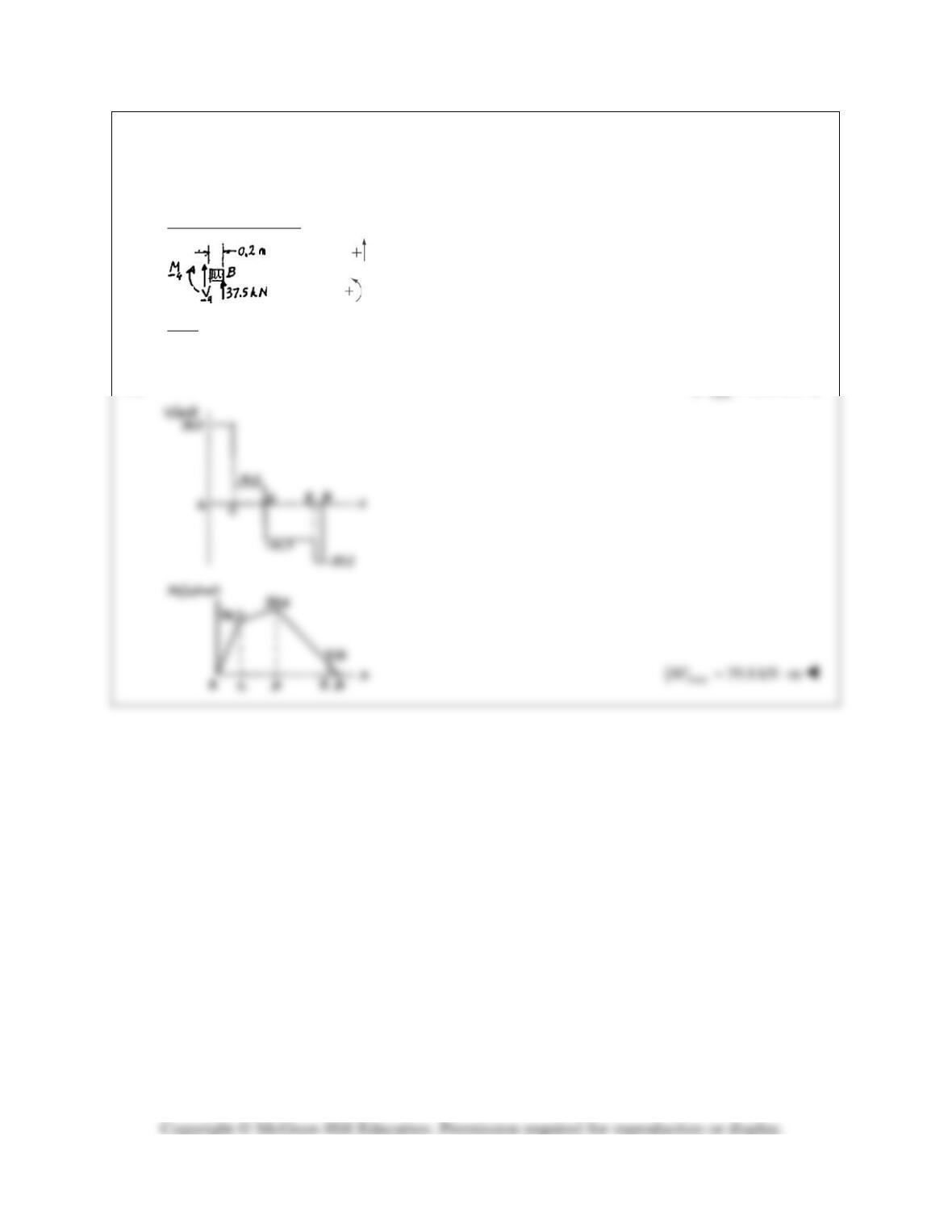
PROBLEM 7.36 (Continued)
Just to the right of E:
4
0: 37.5 0
y
FVΣ= + =
437.5 kNV= −
44
0: (37.5)(0.2) 0MMΣ= − + =
4
7.50 kN mM=+⋅
At B:
0
BB
VM= =
(b)
PROBLEM 7.37
For the beam and loading shown, (a) draw the shear and bending-
moment diagrams, (b) determine the maximum absolute values of the
shear and bending moment.
SOLUTION
Free body: Entire beam
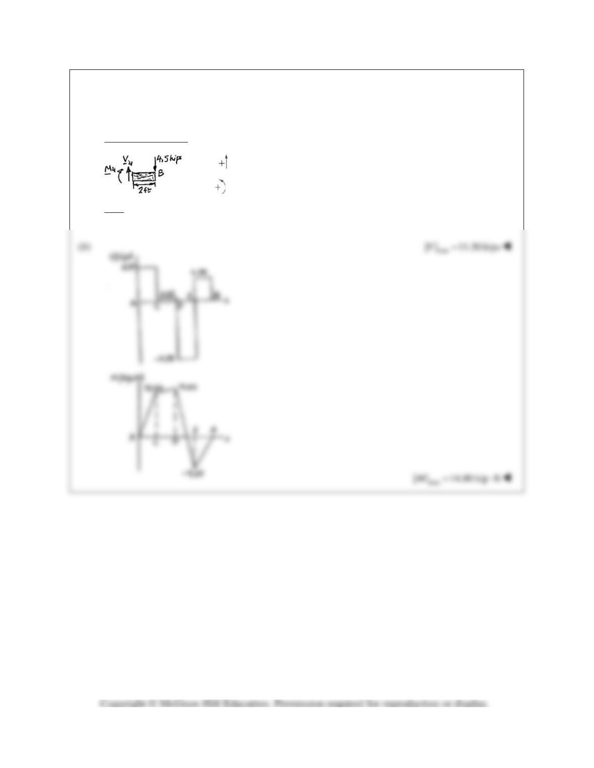
PROBLEM 7.37 (Continued)
Just to the right of E:
4
0: 4.5 0
y
FVΣ= − =
44.5 kipsV= +
44
0: (4.5)2 0MMΣ= − − =
49 kip ftM=−⋅
At B:
0
BB
VM= =
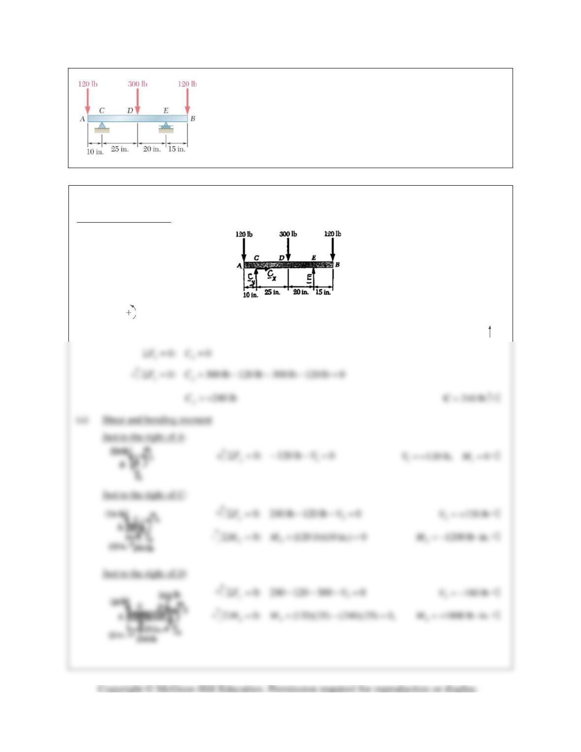
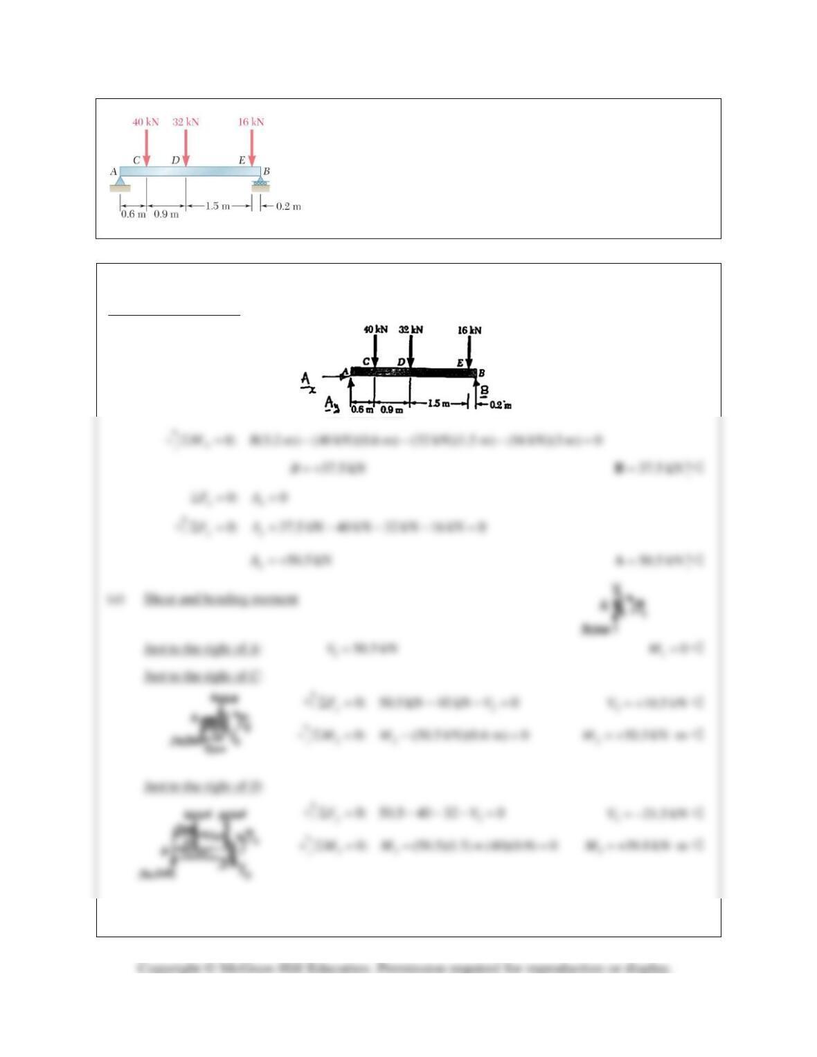
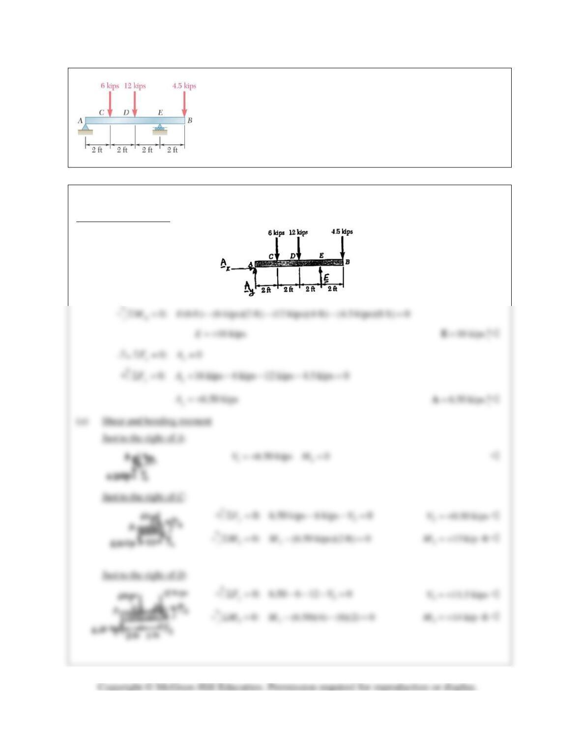
PROBLEM 7.38
For the beam and loading shown, (a) draw the shear and bending-
moment diagrams, (b) determine the maximum absolute values of the
shear and bending moment.
SOLUTION
Free body: Entire beam
0: (120 lb)(10 in.) (300 lb)(25 in.) (45 in.) (120 lb)(60 in.) 0
C
MEΣ= − + − =
300 lbE= +
300 lb=E
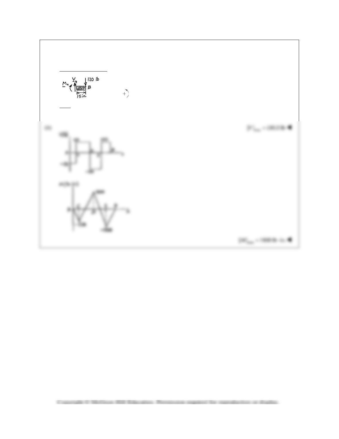
PROBLEM 7.38 (Continued)
Just to the right of E:
4
0: 120 lb 0
y
FV+Σ = − =
4
120 lbV= +
44
0: (120 lb)(15 in.) 0MMΣ= − − =
41800 lb in.M=−⋅
At B:
0
BB
VM= =
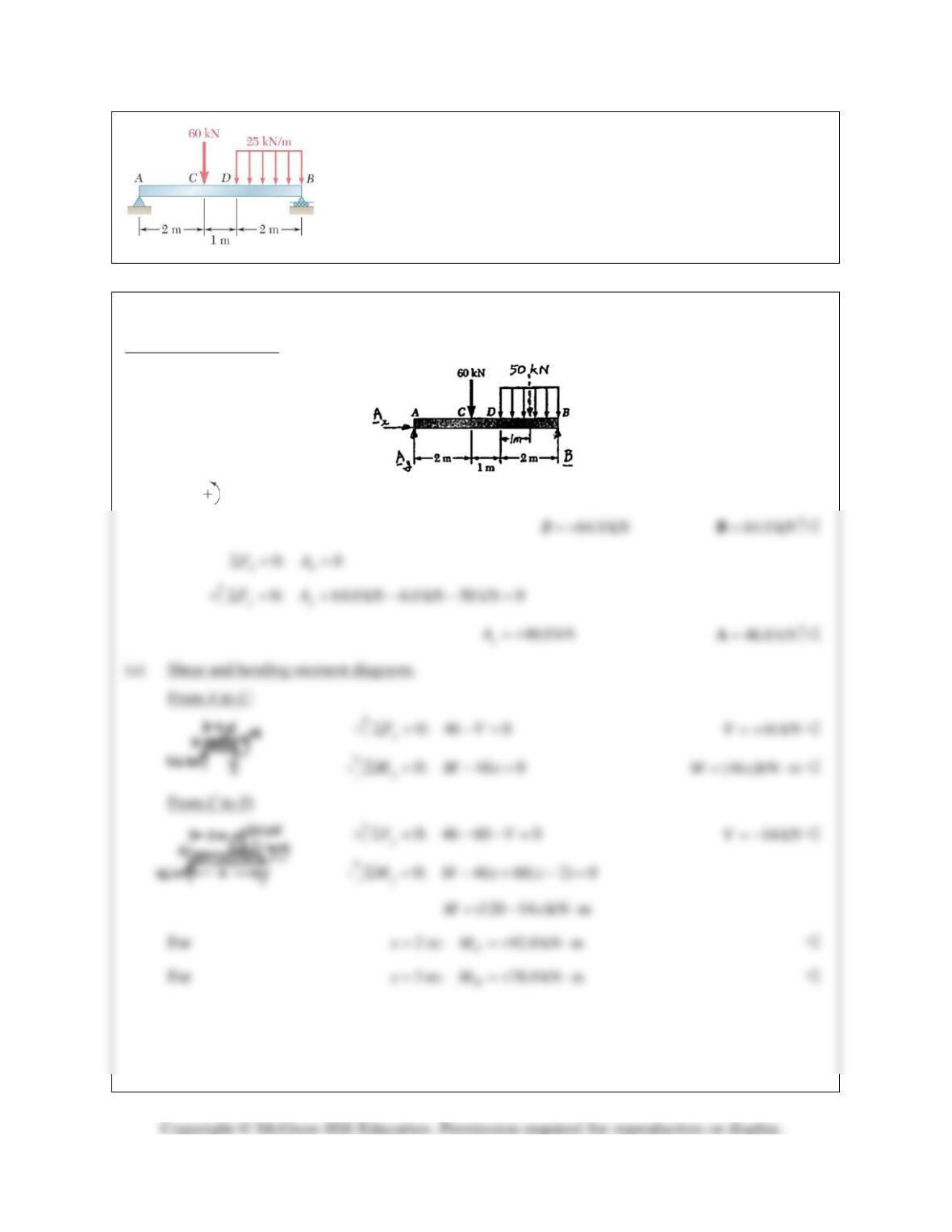
PROBLEM 7.39
For the beam and loading shown, (a) draw the shear and bending-moment
diagrams, (b) determine the maximum absolute values of the shear and
bending moment.
SOLUTION
Free body: Entire beam
0: (5 m) (60 kN)(2 m) (50 kN)(4 m) 0
A
MBΣ= − − =
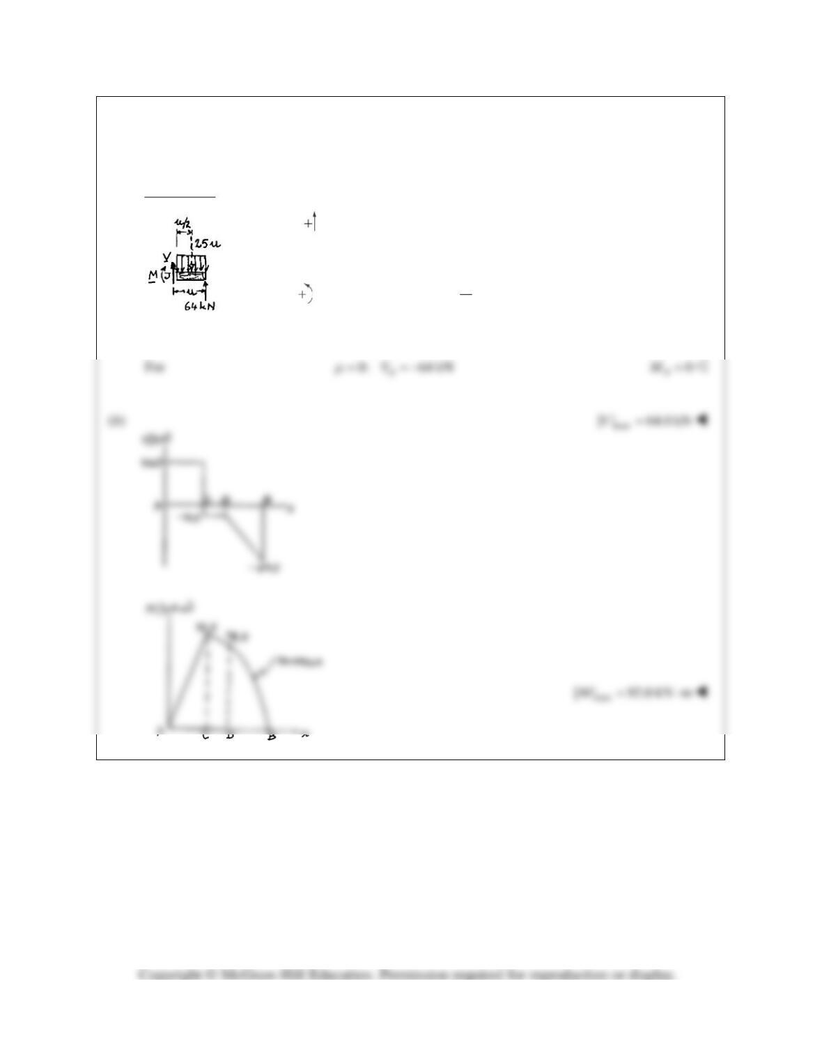
PROBLEM 7.39 (Continued)
From D to B:
0: 64 25 0
y
FV
µ
Σ= +− =
(25 64)kNV
µ
= −
0: 64 (25 ) 0
2
j
MM
µ
µµ
Σ = − −=
2
(64 12.5 )kN mM
µµ
=−⋅
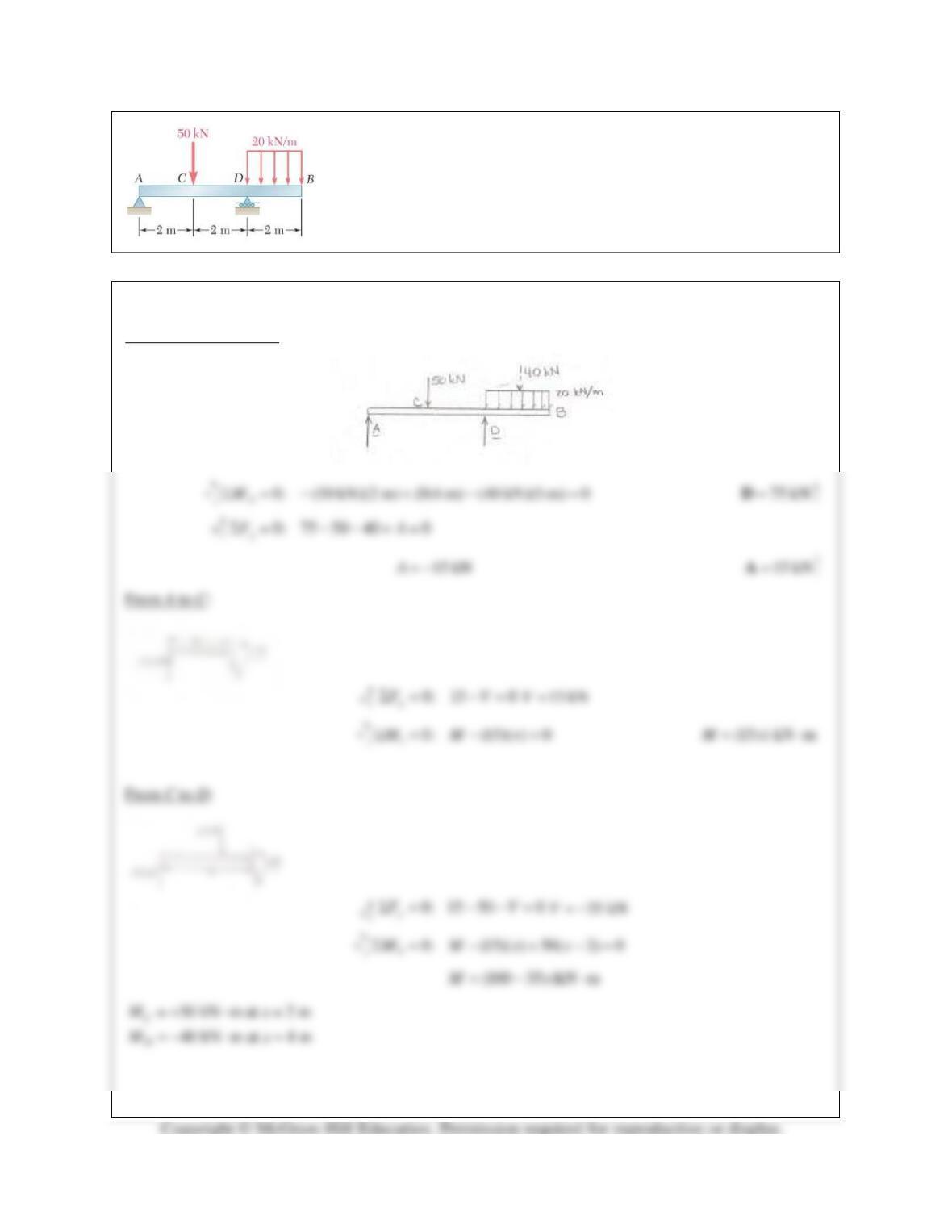
PROBLEM 7.40
For the beam and loading shown, (a) draw the shear and bending-moment
diagrams, (b) determine the maximum absolute values of the shear and
bending moment.
SOLUTION
Free body: Entire beam
PROBLEM 7.40 (Continued)
From D to B:
0: 20 0
y
F VxΣ= − =
20 kNVx= +
30: (20 ) 0
2
x
M Mx
Σ = −− =
2
10 kN mMx=−⋅
40 kN, 40 kN m at 2 m
0 at 0
DD
BB
VM x
VM x
= =−⋅ =
= = =
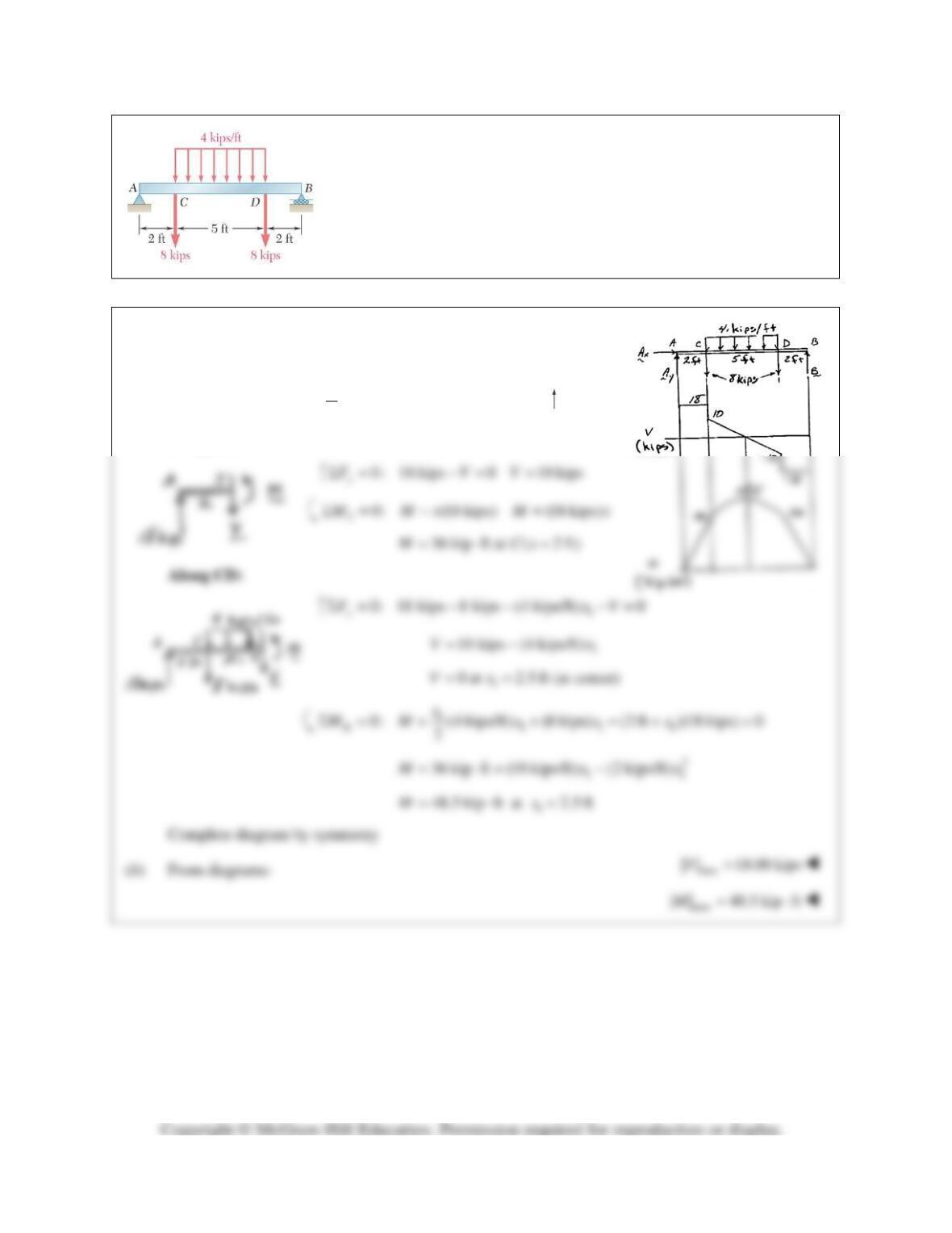
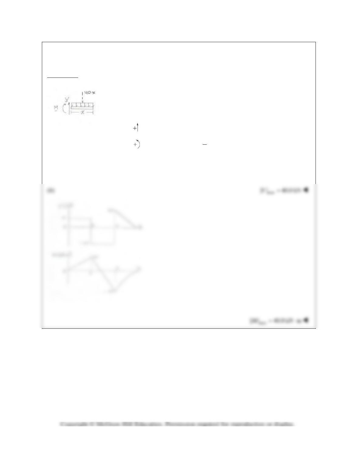
PROBLEM 7.41
For the beam and loading shown, (a) draw the shear and bending-moment
diagrams, (b) determine the maximum absolute values of the shear and
bending moment.
SOLUTION
(a) By symmetry:
1
8 kips (4 kips)(5 ft) 18 kips
2
yy
AB==+==AB
Along AC:
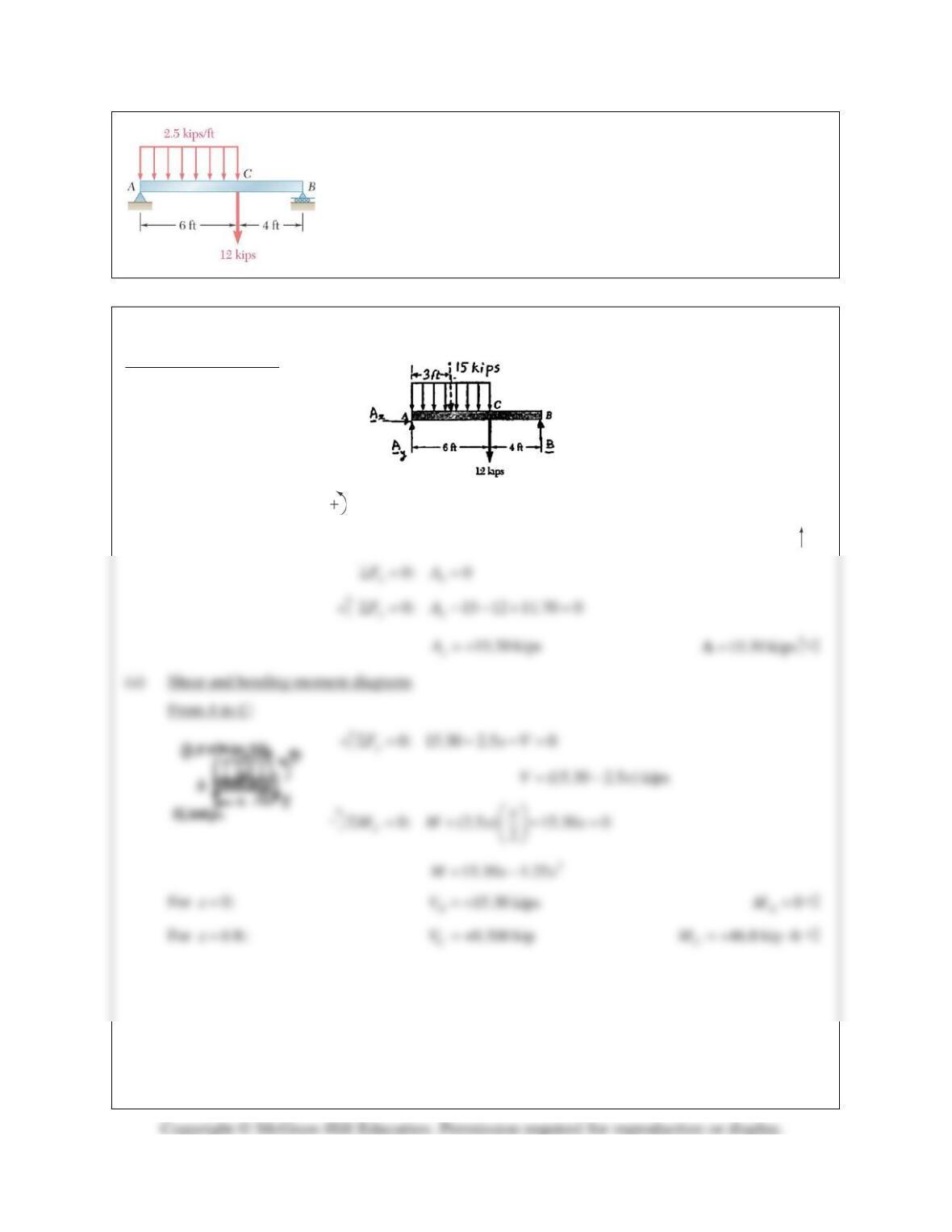
PROBLEM 7.42
For the beam and loading shown, (a) draw the shear and bending-moment
diagrams, (b) determine the maximum absolute values of the shear and
bending moment.
SOLUTION
Free body: Entire beam
0: (10 ft) (15 kips)(3 ft) (12 kips)(6 ft) 0
A
MBΣ= − − =
11.70 kipsB= +
11.70 kips=B
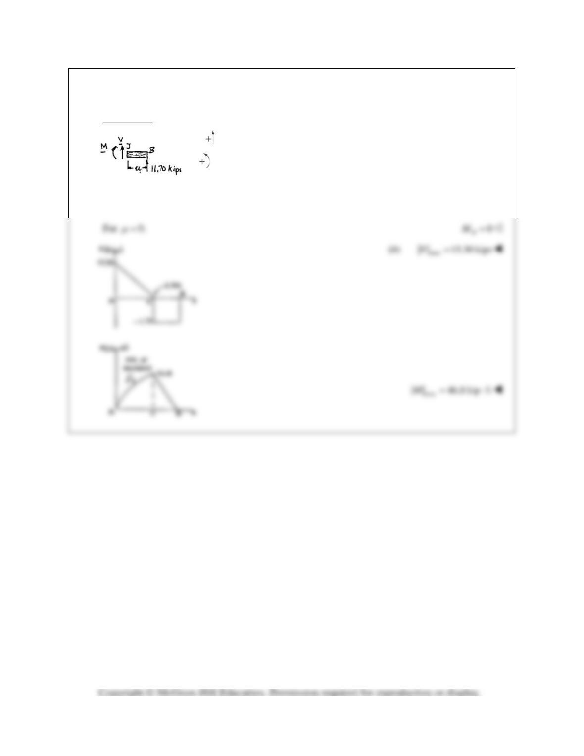
PROBLEM 7.42 (Continued)
From C to B:
0: 11.70 0
y
FVΣ= + =
11.70 kipsV= −
0: 11.70 0
J
MM
µ
Σ = −=
(11.70 ) kip ftM
µ
= ⋅
For
4 ft:
µ
=
46.8 kip ft
C
M=+⋅