PROBLEM 6.133
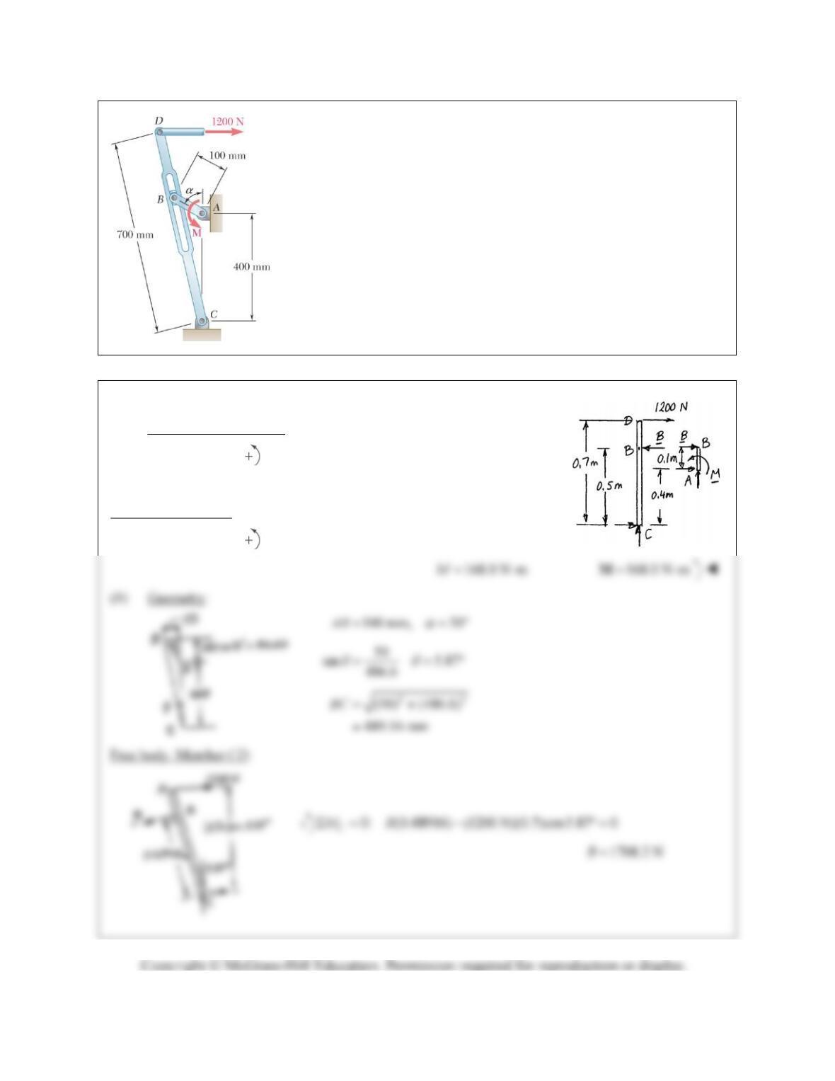
The Whitworth mechanism shown is used to produce a quick-return
motion of Point D. The block at B is pinned to the crank AB and is free to
slide in a slot cut in member CD. Determine the couple M that must be
applied to the crank AB to hold the mechanism in equilibrium when
(a) α 0, (b) α 30°.
SOLUTION
(a) Free body: Member CD:
0: (0.5 m) (1200 N)(0.7 m) 0
C
MB
1680 NB
Free body: Crank AB:
0: (1680 N)(0.1 m) 0
A
MM
PROBLEM 6.133 (Continued)
Free body: Crank AB:
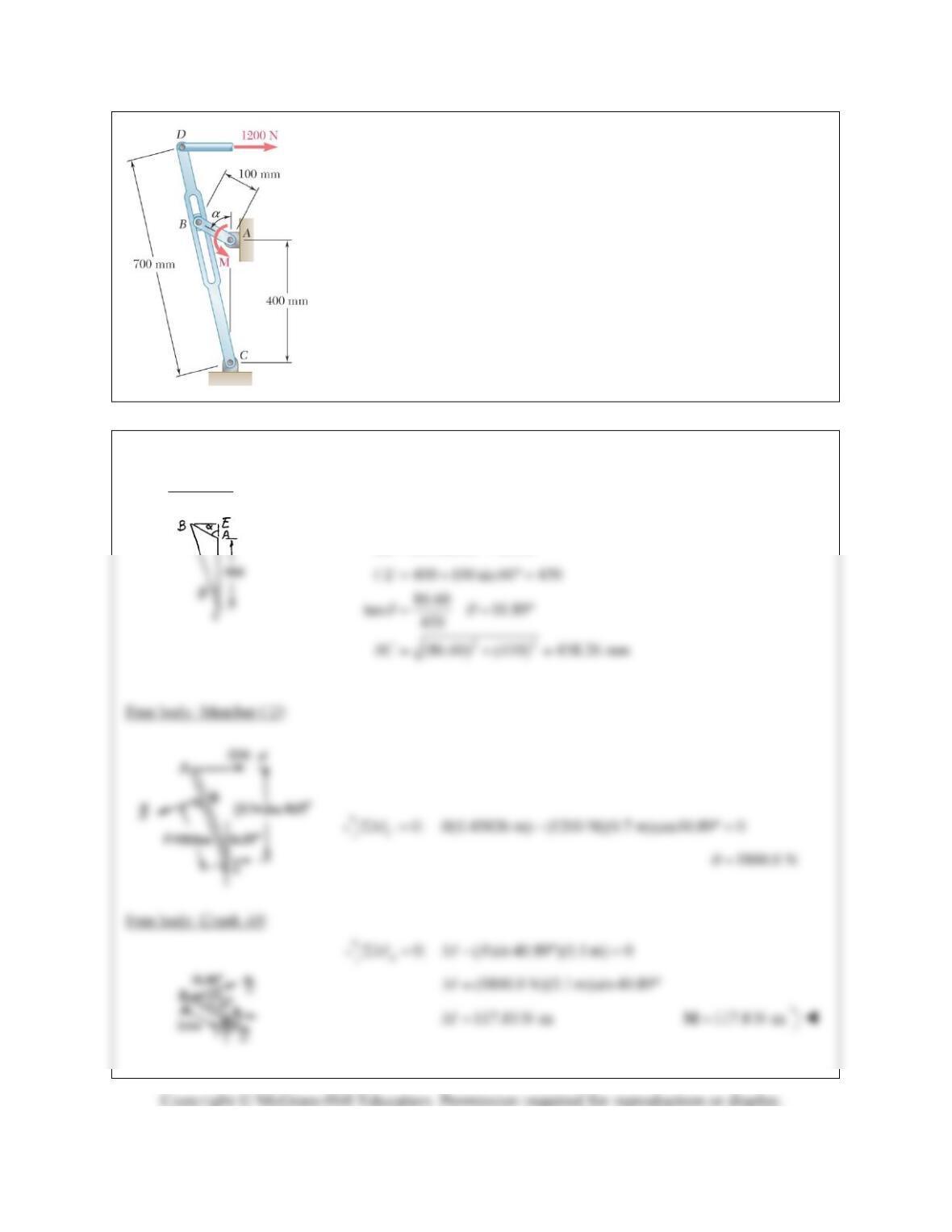
PROBLEM 6.134
Solve Problem 6.133 when (a) α 60, (b) α 90.
PROBLEM 6.133 The Whitworth mechanism shown is used to produce
a quick-return motion of Point D. The block at B is pinned to the crank
AB and is free to slide in a slot cut in member CD. Determine the couple
M that must be applied to the crank AB to hold the mechanism in
equilibrium when (a) α 0, (b) α 30°.
SOLUTION
(a) Geometry:
100 mm, 60°AB
100 cos 60 86.60BE
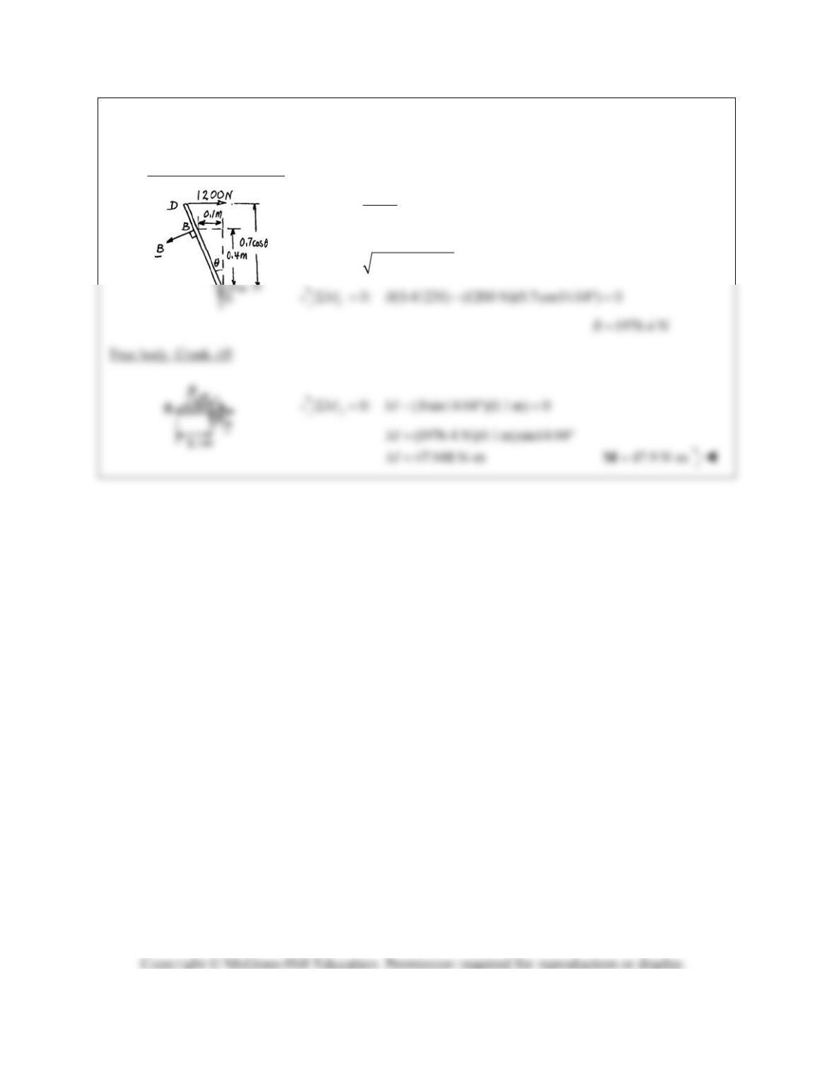
PROBLEM 6.134 (Continued)
(b) Free body: Member CD:
22
0.1 m
tan 0.4 m
14.04
(0.1) (0.4) 0.41231 mBC
PROBLEM 6.135
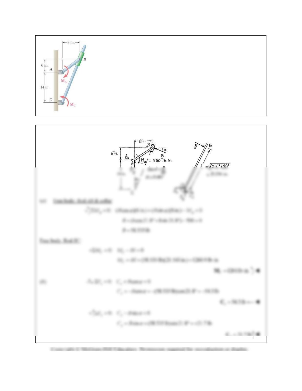
Two rods are connected by a frictionless collar B. Knowing that the magnitude
of the couple
MA
is 500 lb · in., determine (a) the couple
MC
required for
equilibrium, (b) the corresponding components of the reaction at C.
SOLUTION
y
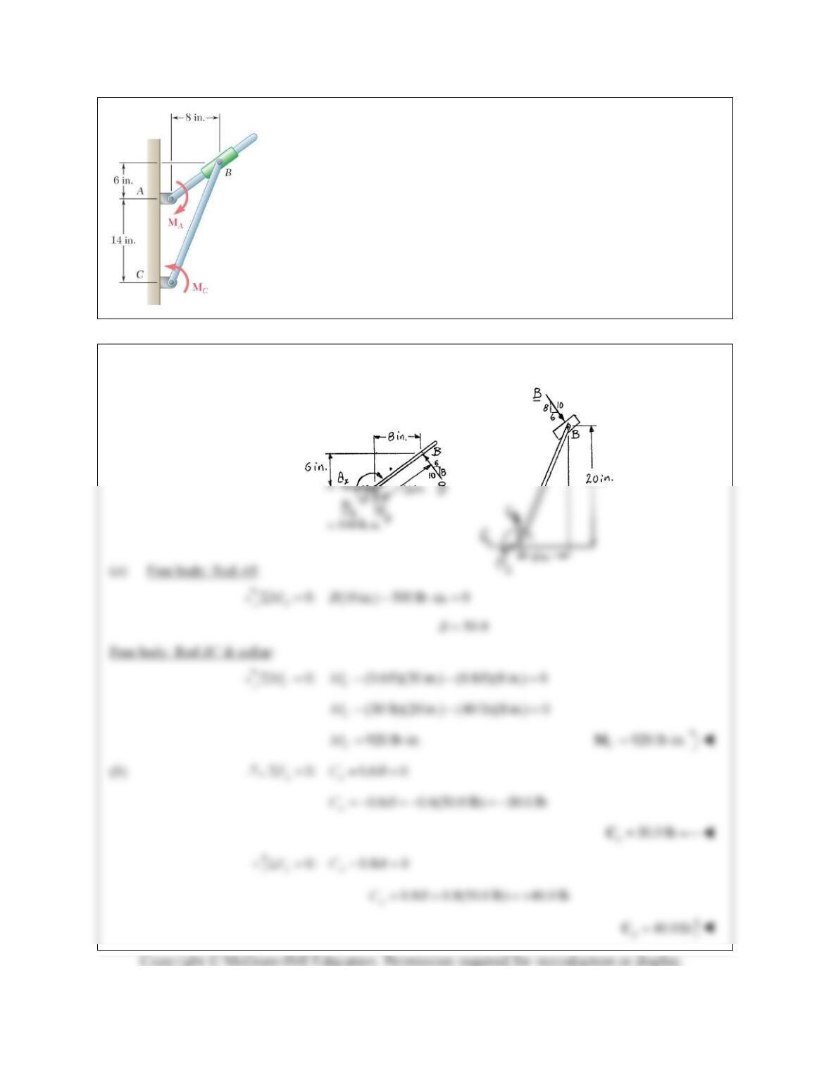
PROBLEM 6.136
Two rods are connected by a frictionless collar B. Knowing that the
magnitude of the couple
MA
is 500 lb · in., determine (a) the couple
MC
required for equilibrium, (b) the corresponding components of the reaction
at C.
SOLUTION
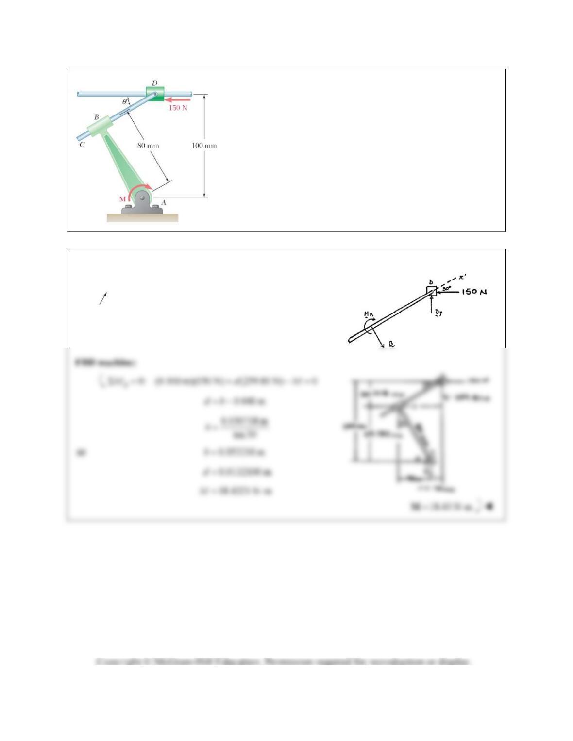
PROBLEM 6.137
Rod CD is attached to the collar D and passes through a collar
welded to end B of lever AB. Neglecting the effect of friction,
determine the couple
M
required to hold the system in equilibrium
when
30 .
SOLUTION
FBD
DC
:
0: sin 30 (150 N) cos30 0
xy
FD
(150 N) ctn 30 259.81 N
y
D
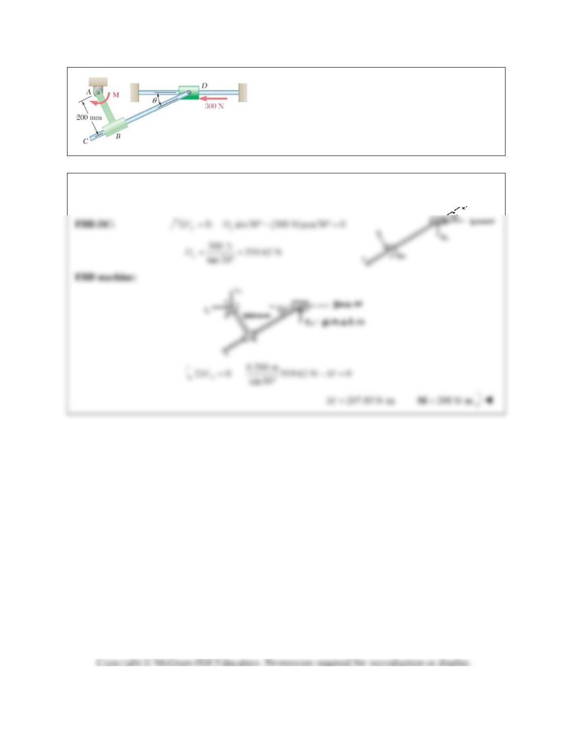
PROBLEM 6.138
Rod CD is attached to the collar D and passes through a
collar welded to end B of lever AB. Neglecting the effect
of friction, determine the couple
M
required to hold the
system in equilibrium when
30 .
SOLUTION
Note:
CD
B
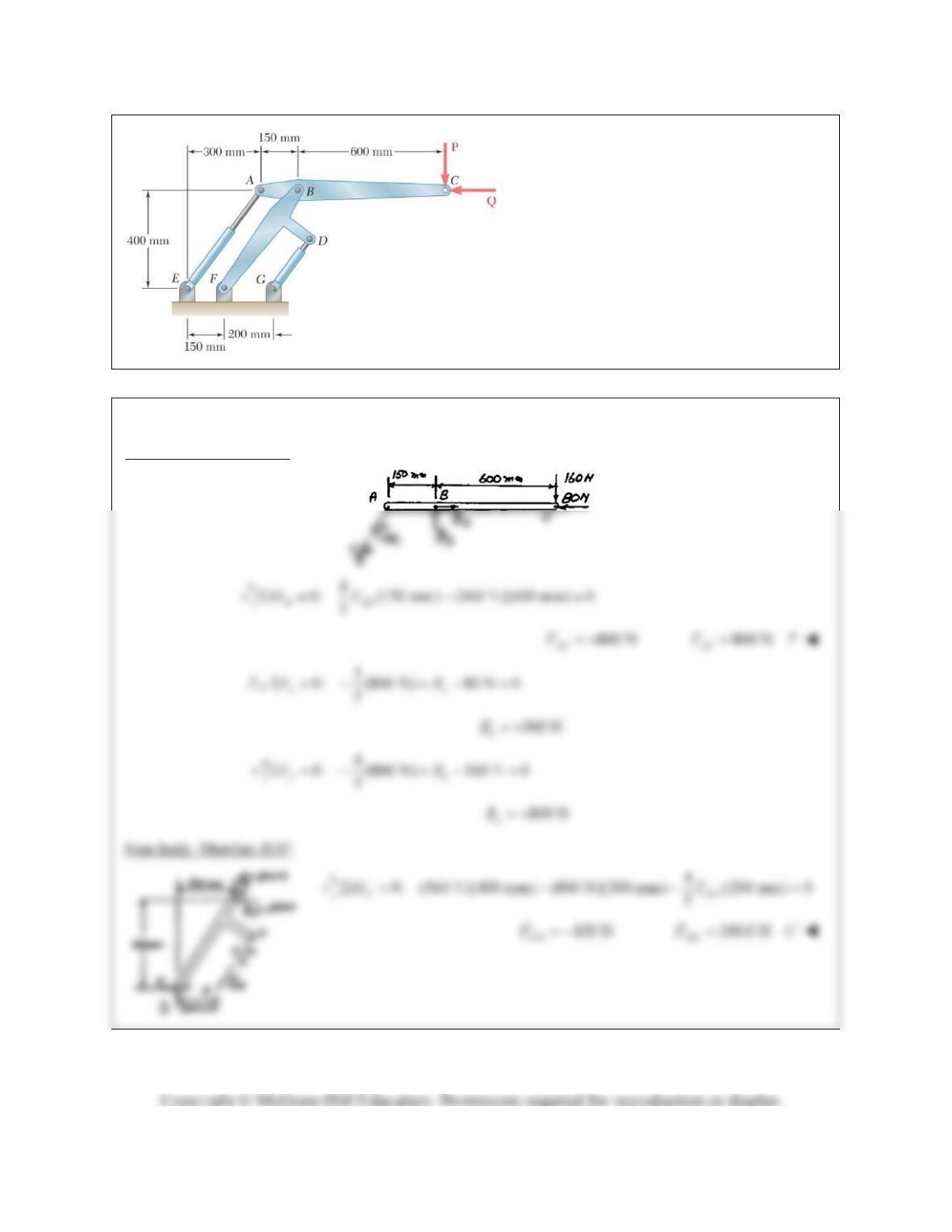
PROBLEM 6.139
Two hydraulic cylinders control the position
of the robotic arm ABC. Knowing that in the
position shown the cylinders are parallel,
determine the force exerted by each cylinder
when
160 NP
and
80 N.Q
SOLUTION
Free body: Member ABC:
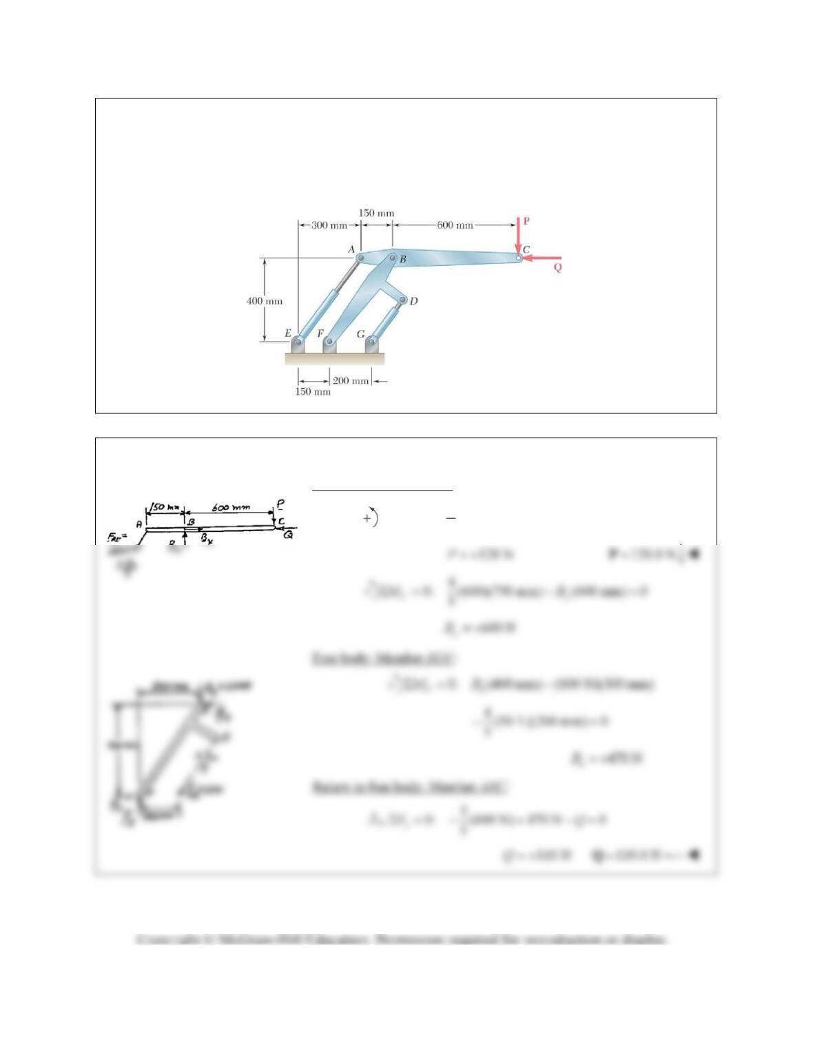
PROBLEM 6.140
Two hydraulic cylinders control the position of the robotic arm ABC. In the position shown, the cylinders
are parallel and both are in tension. Knowing the
600 N
AE
F
and
50 N,
DG
F
determine the forces
P
and
Q
applied at C to arm ABC.
SOLUTION
Free body: Member ABC:
4
0: (600 N)(150 mm) (600 mm) 0
5
B
MP
PROBLEM 6.141
A 39-ft length of railroad rail of weight 44 lb/ft is lifted by the tongs
shown. Determine the forces exerted at D and F on tong BDF.
SOLUTION
Free body: Rail:
(39ft)(44lb/ft) 1716lbW
By symmetry,
1858 lb
2
yy
EF W
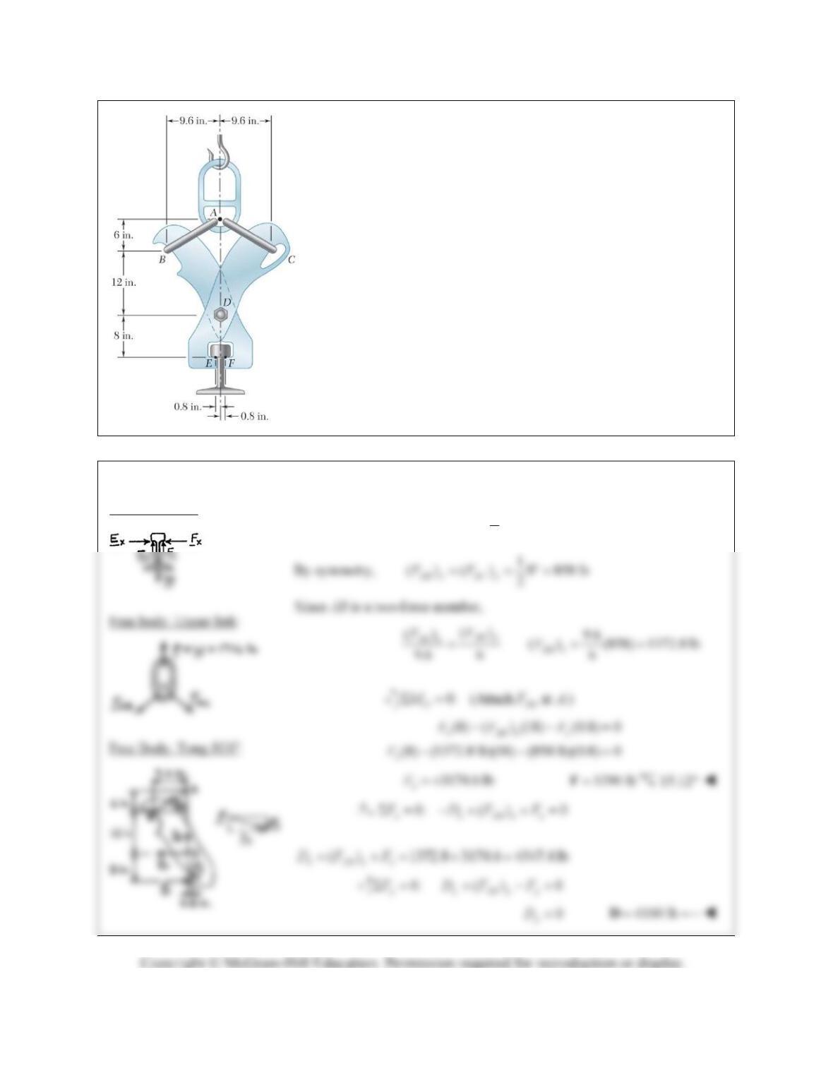
PROBLEM 6.142
A log weighing 800 lb is lifted by a pair of tongs as shown.
Determine the forces exerted at E and F on tong DEF.
SOLUTION
FBD
AB
:
By symmetry:
400 lb
yy
AB
and
6(400 lb)
xx
AB
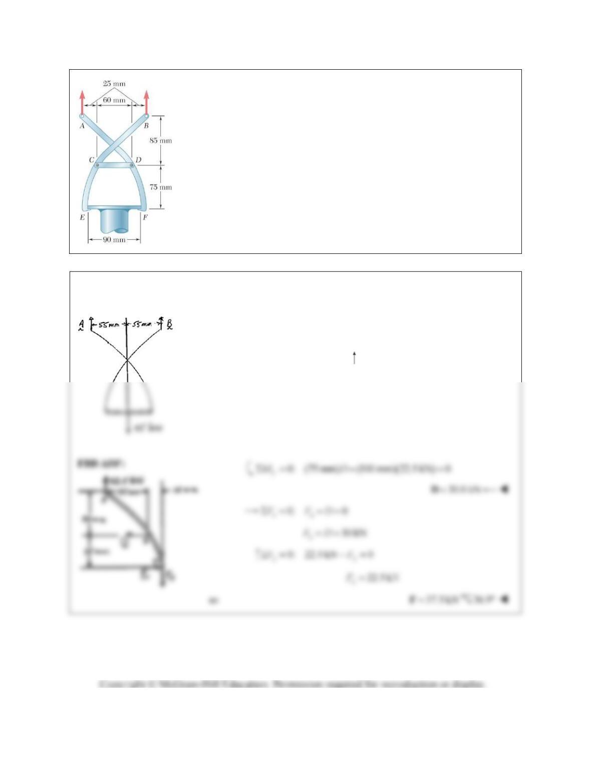
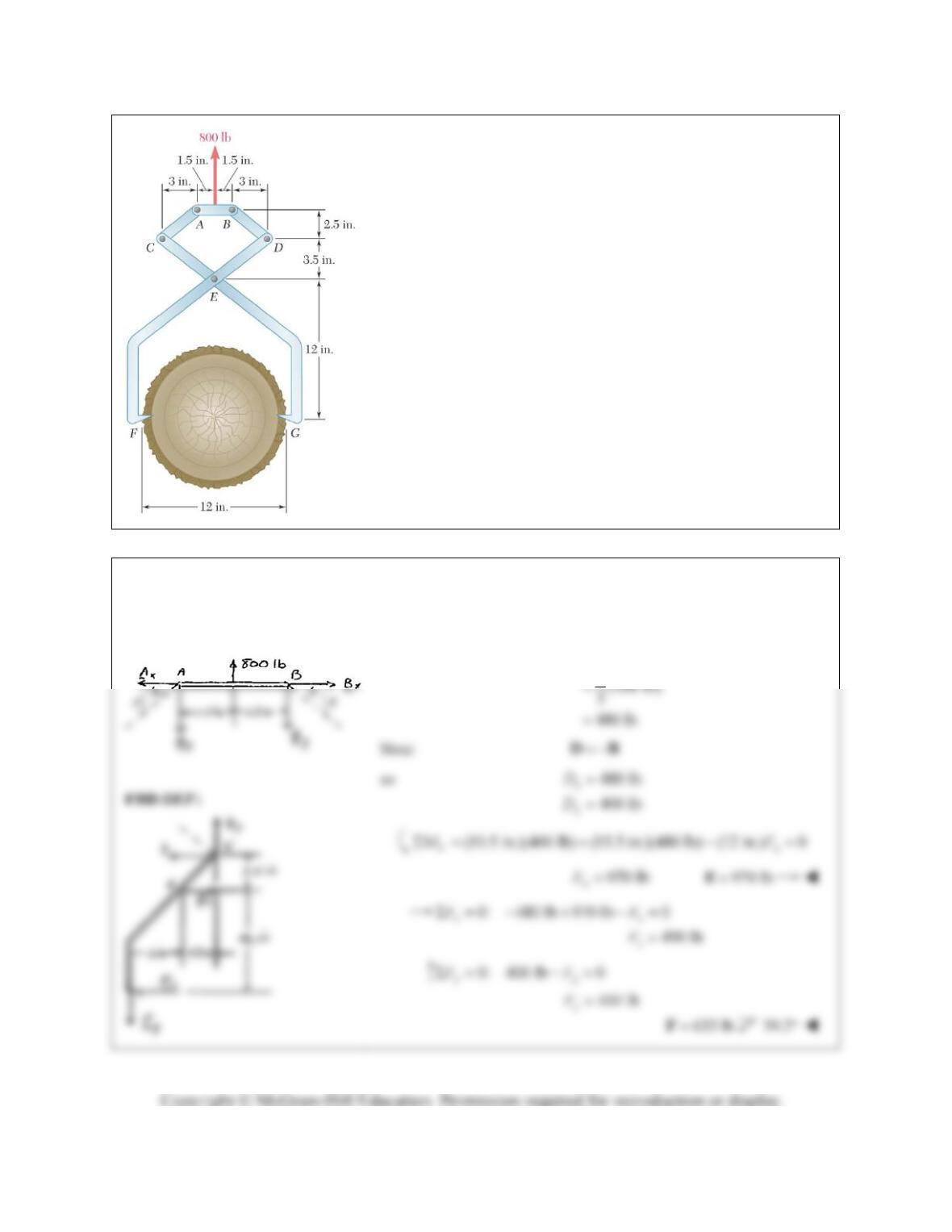
PROBLEM 6.143
The tongs shown are used to apply a total upward force of 45 kN on a pipe cap.
Determine the forces exerted at D and F on tong ADF.
SOLUTION
FBD whole:
By symmetry,
22.5 kN
AB
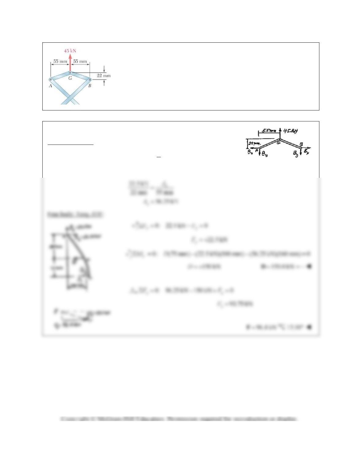
PROBLEM 6.144
If the toggle shown is added to the tongs of Problem 6.141 and a single
vertical force is applied at G, determine the forces exerted at D and F on
tong ADF.
SOLUTION
Free body: Toggle:
By symmetry,
1(45 kN) 22.5 kN
2
y
A
AG is a two-force member.
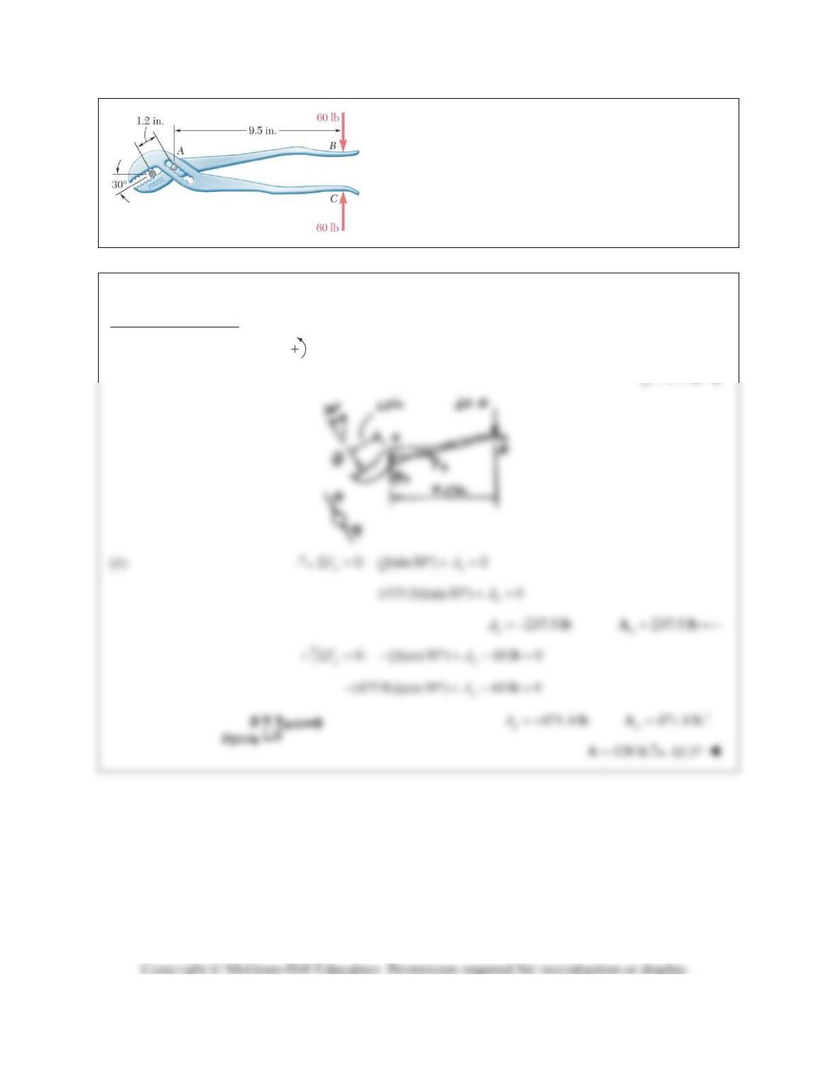
PROBLEM 6.145
The pliers shown are used to grip a 0.3-in.-diameter rod.
Knowing that two 60-lb forces are applied to the handles,
determine (a) the magnitude of the forces exerted on the
rod, (b) the force exerted by the pin at A on portion AB of
the pliers.
SOLUTION
Free body: Portion AB:
(a)
0: (1.2 in.) (60 lb)(9.5 in.) 0
A
MQ
475 lbQ
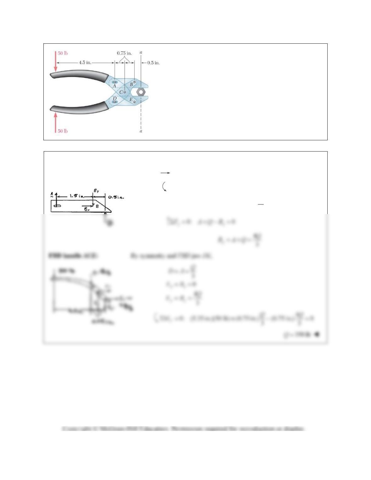
PROBLEM 6.146
Determine the magnitude of the gripping forces exerted
along line aa on the nut when two 50-lb forces are applied
to the handles as shown. Assume that pins A and D slide
freely in slots cut in the jaws.
SOLUTION
FBD jaw
AB
:
0: 0
xx
FB
0: (0.5 in.) (1.5 in.) 0
B
MQA
3
Q
A
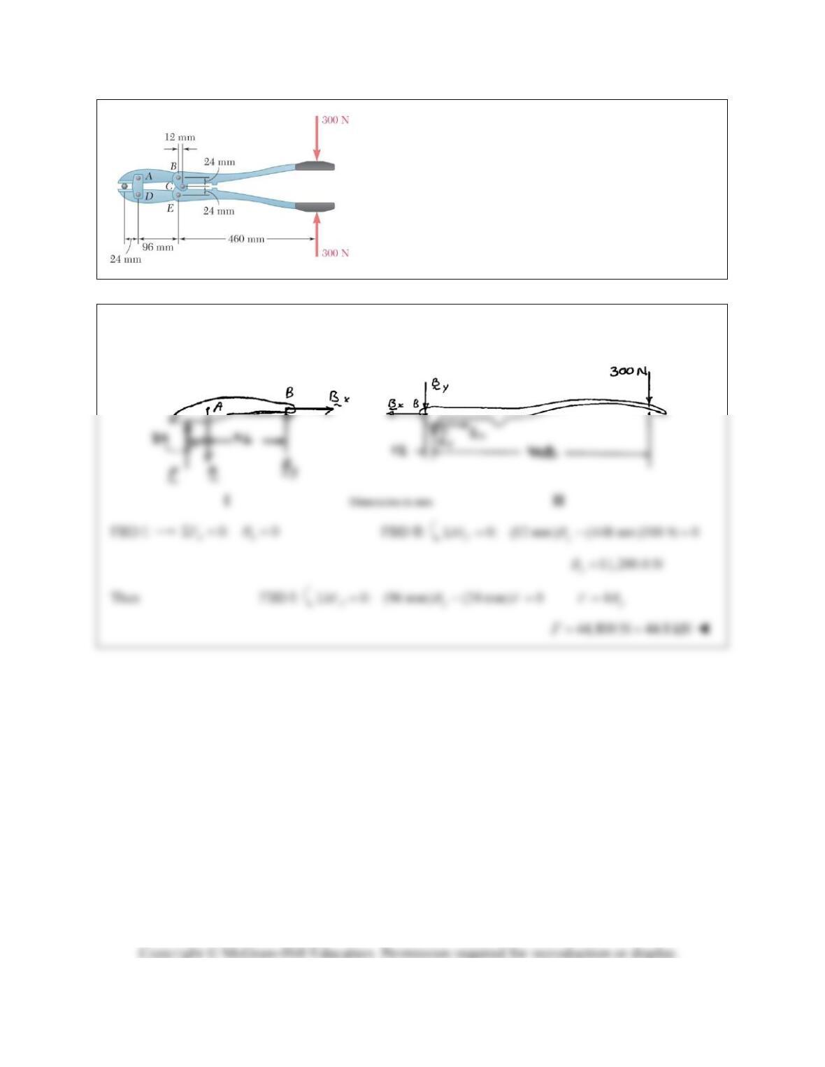
PROBLEM 6.147
In using the bolt cutter shown, a worker applies two 300-N
forces to the handles. Determine the magnitude of the
forces exerted by the cutter on the bolt.
SOLUTION
FBD cutter
AB
: FBD handle
BC
:
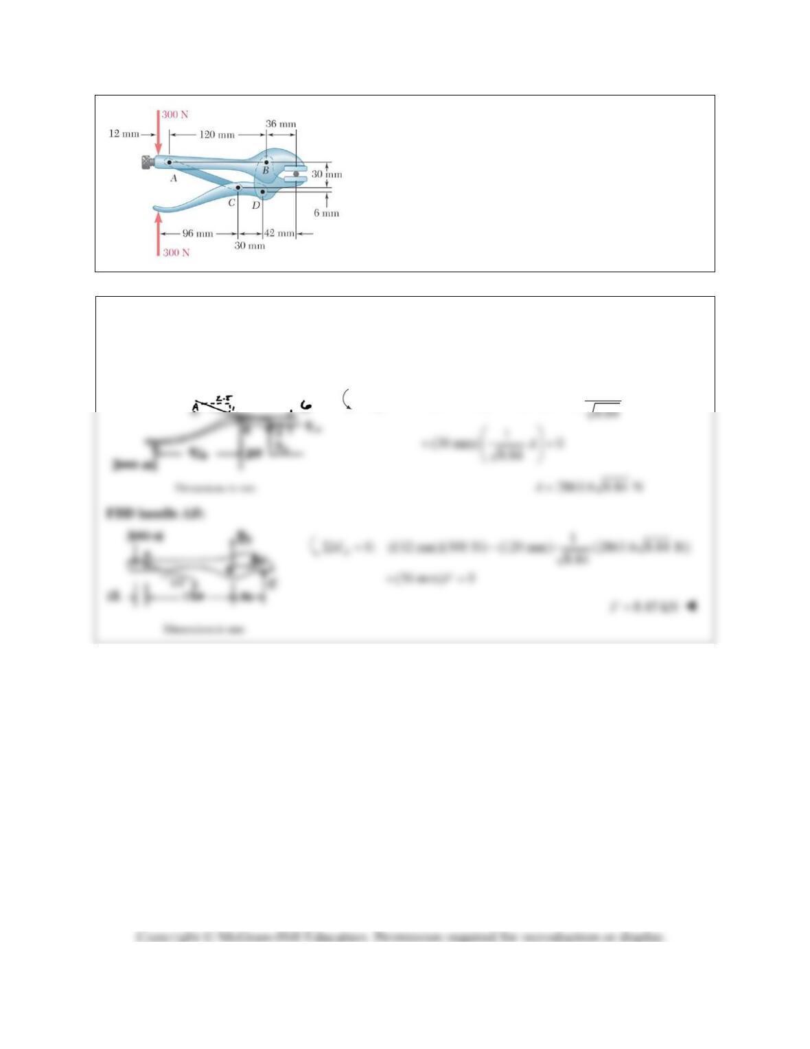
PROBLEM 6.148
Determine the magnitude of the gripping forces produced
when two 300-N forces are applied as shown.
SOLUTION
We note that AC is a two-force member.
FBD handle
CD
:
2.8
0: (126 mm)(300 N) (6 mm) 8.84
D
MA
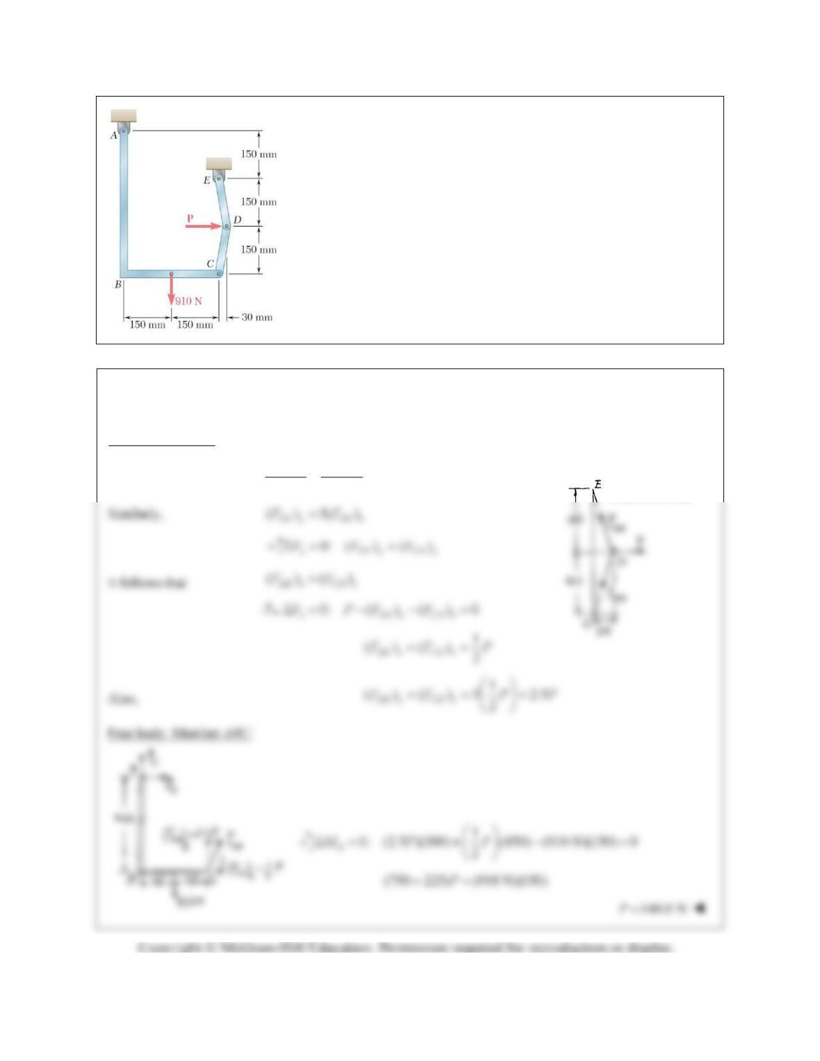
PROBLEM 6.149
Determine the force
P
that must be applied to the toggle CDE to
maintain bracket ABC in the position shown.
SOLUTION
We note that CD and DE are two-force members.
Free body: Joint D:
()
() ()5()
30 150
CD y
CD x
CD y CD x
F
FFF
Dimensions in mm
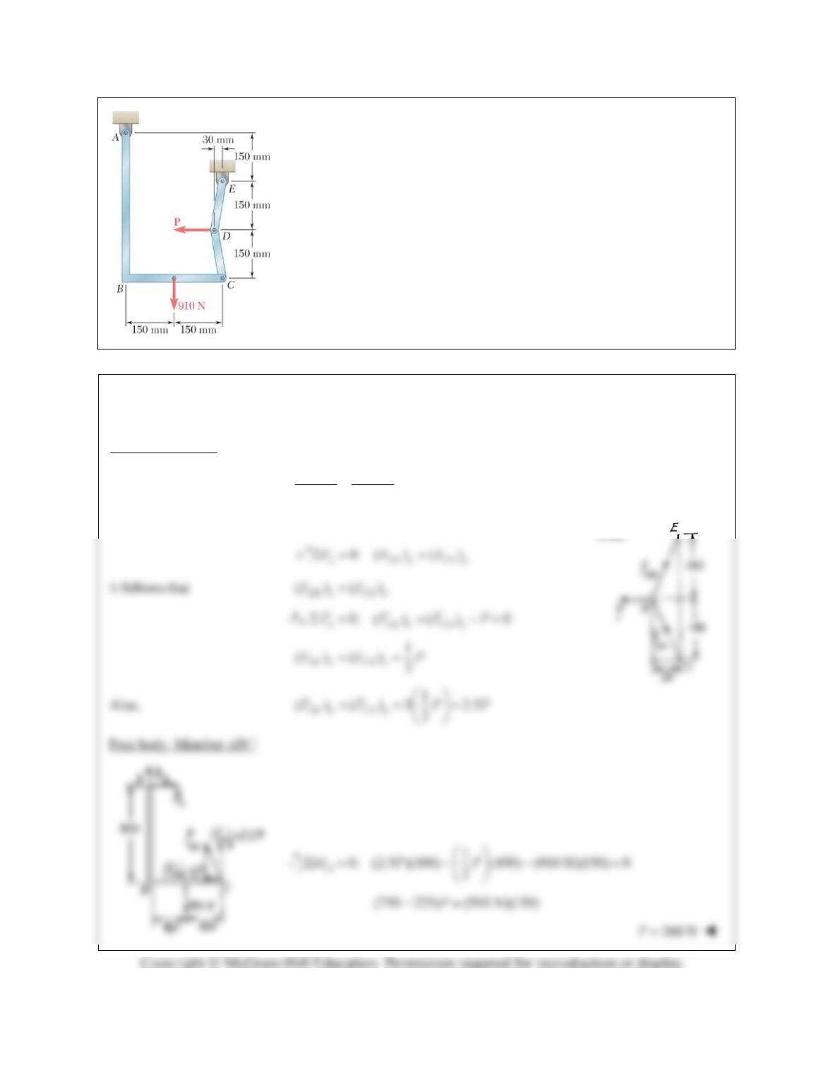
PROBLEM 6.150
Determine the force
P
that must be applied to the toggle CDE to maintain
bracket ABC in the position shown.
SOLUTION
We note that CD and DE are two-force members.
Free body: Joint D:
()
() ()5()
30 150
CD y
CD x
CD y CD x
F
FFF
Similarly,
()5()
DE y DE x
FF
Dimensions