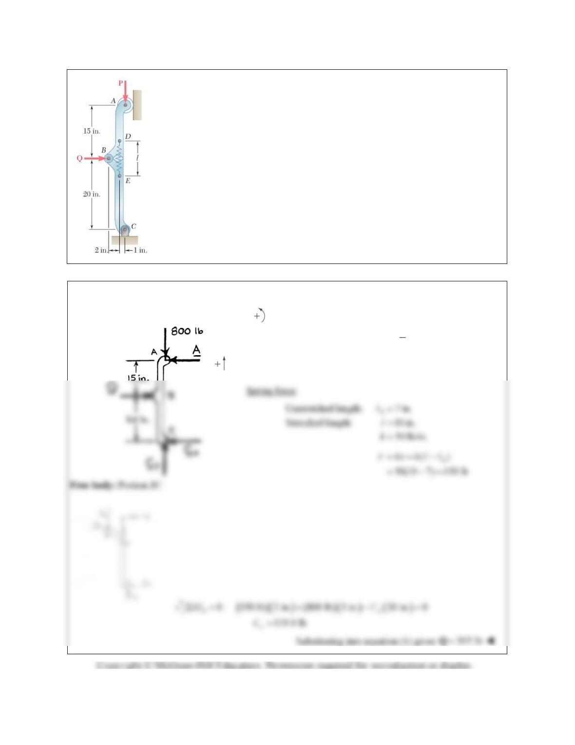
PROBLEM 6.151
Since the brace shown must remain in position even when the magnitude of
P
is
very small, a single safety spring is attached at D and E. The spring DE has a
constant of 50 lb/in. and an unstretched length of 7 in. Knowing that l = 10 in. and
that the magnitude of
P
is 800 lb, determine the force
Q
required to release the
brace.
SOLUTION
Free body:
0 : 15 in. 35 in. 0
Ax
MQ C
7 (1)
3
x
QC
0: 800 lb 0 or 800 lb
yy y
FC C
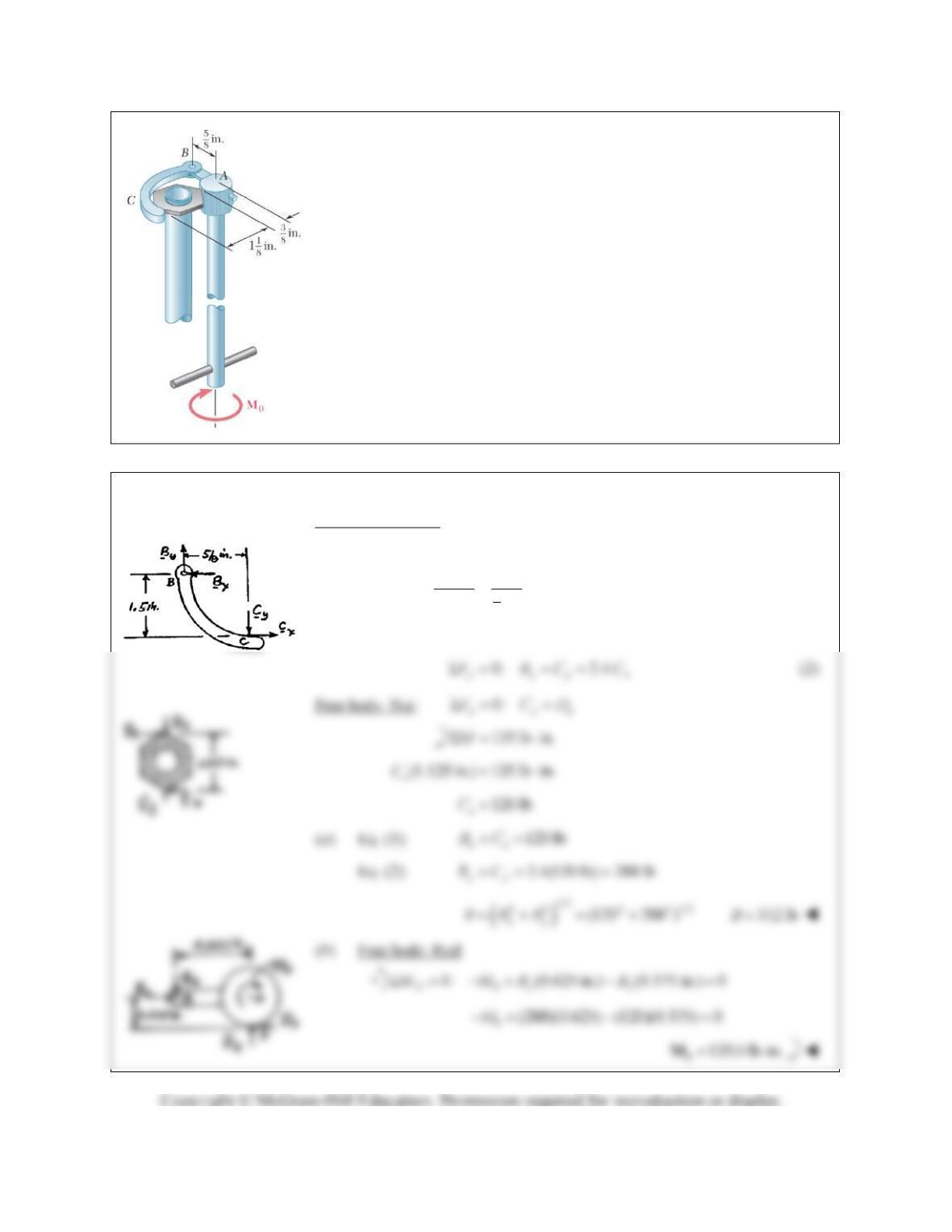
PROBLEM 6.152
The specialized plumbing wrench shown is used in confined areas (e.g.,
under a basin or sink). It consists essentially of a jaw BC pinned at B to a
long rod. Knowing that the forces exerted on the nut are equivalent to a
clockwise (when viewed from above) couple of magnitude 135 lb in.,
determine (a) the magnitude of the force exerted by pin B on jaw BC,
(b) the couple
M0
that is applied to the wrench.
SOLUTION
Free body: Jaw BC:
This is a two-force member.
5
8
2.4
1.5 in. in.
yx
yx
CCCC
0:
xxx
FBC
(1)
PROBLEM 6.153
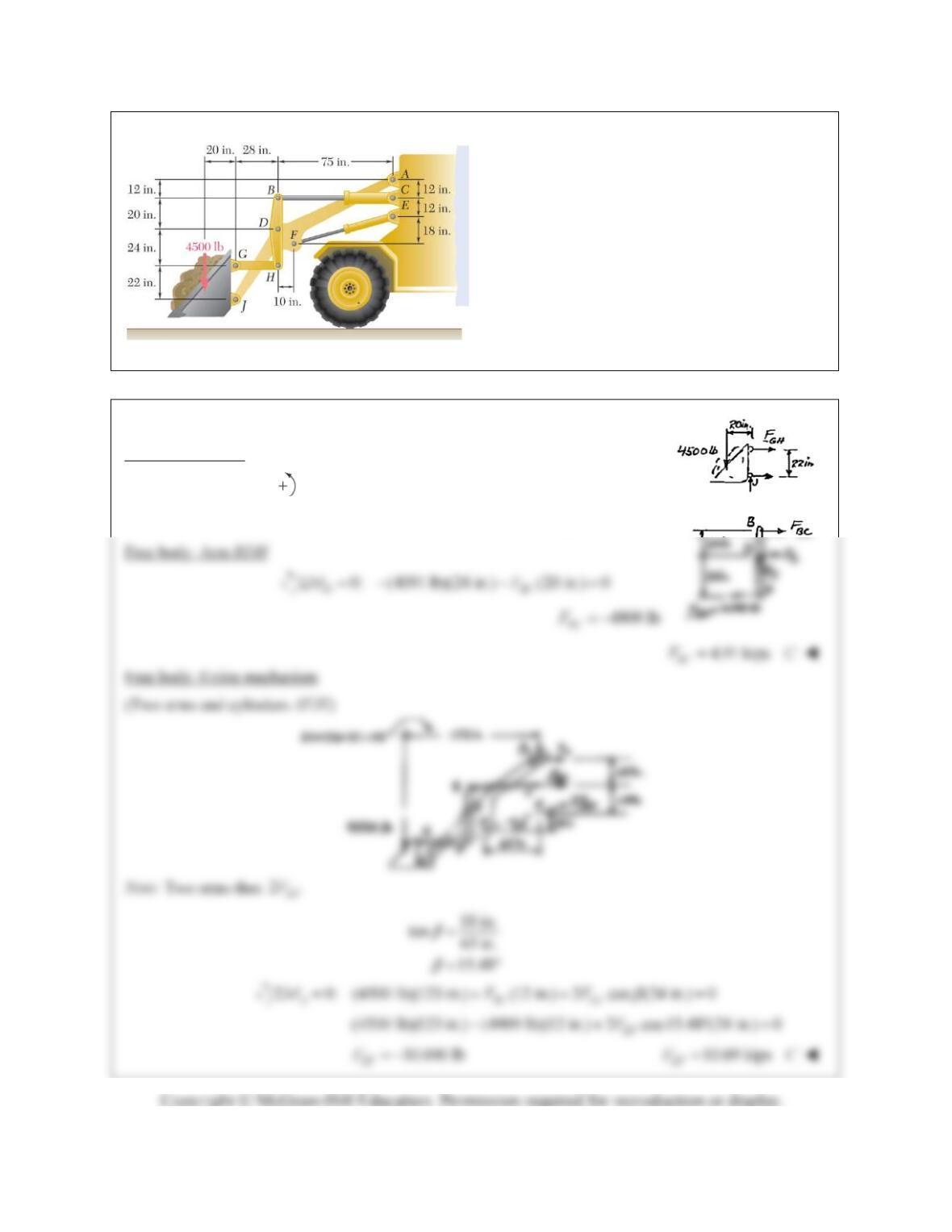
The motion of the bucket of the front-end loader
shown is controlled by two arms and a linkage
that are pin-connected at D. The arms are located
symmetrically with respect to the central,
vertical, and longitudinal plane of the loader; one
arm AFJ and its control cylinder EF are shown.
The single linkage GHDB and its control cylinder
BC are located in the plane of symmetry. For the
position and loading shown, determine the force
exerted (a) by cylinder BC, (b) by cylinder EF.
SOLUTION
Free body: Bucket
0: (4500 lb)(20 in.) (22 in.) 0
JGH
MF
4091 lb
GH
F
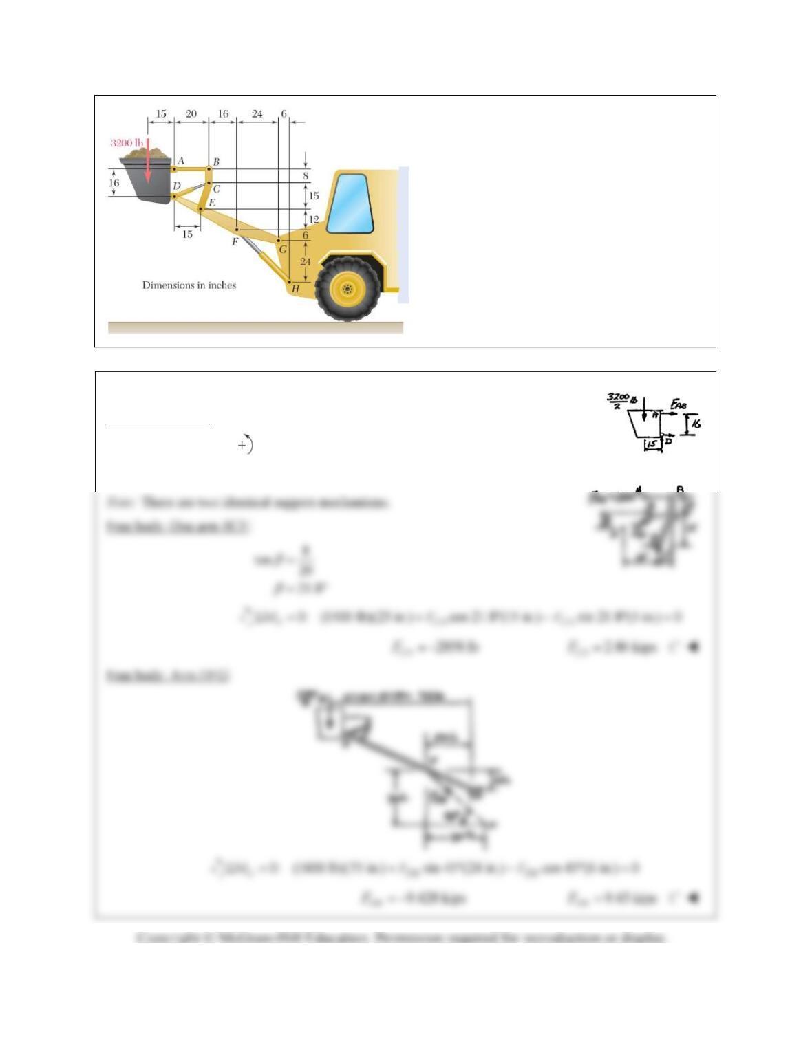
PROBLEM 6.154
The bucket of the front-end loader shown carries a
3200–lb load. The motion of the bucket is
controlled by two identical mechanisms, only
one of which is shown. Knowing that the
mechanism shown supports one-half of the
3200-lb load, determine the force exerted (a) by
cylinder CD, (b) by cylinder FH.
SOLUTION
Free body: Bucket: (one mechanism)
0: (1600 lb)(15 in.) (16 in.) 0
DAB
MF
1500 lb
AB
F

PROBLEM 6.155
The telescoping arm ABC is used to provide an elevated
platform for construction workers. The workers and the
platform together have a mass of 200 kg and have a
combined center of gravity located directly above C. For the
position when
20, determine (a) the force exerted at B
by the single hydraulic cylinder BD, (b) the force exerted on
the supporting carriage at A.
SOLUTION
Geometry:
(5 m) cos 20 4.6985 m
(2.4 m) cos 20 2.2553 m
a
b
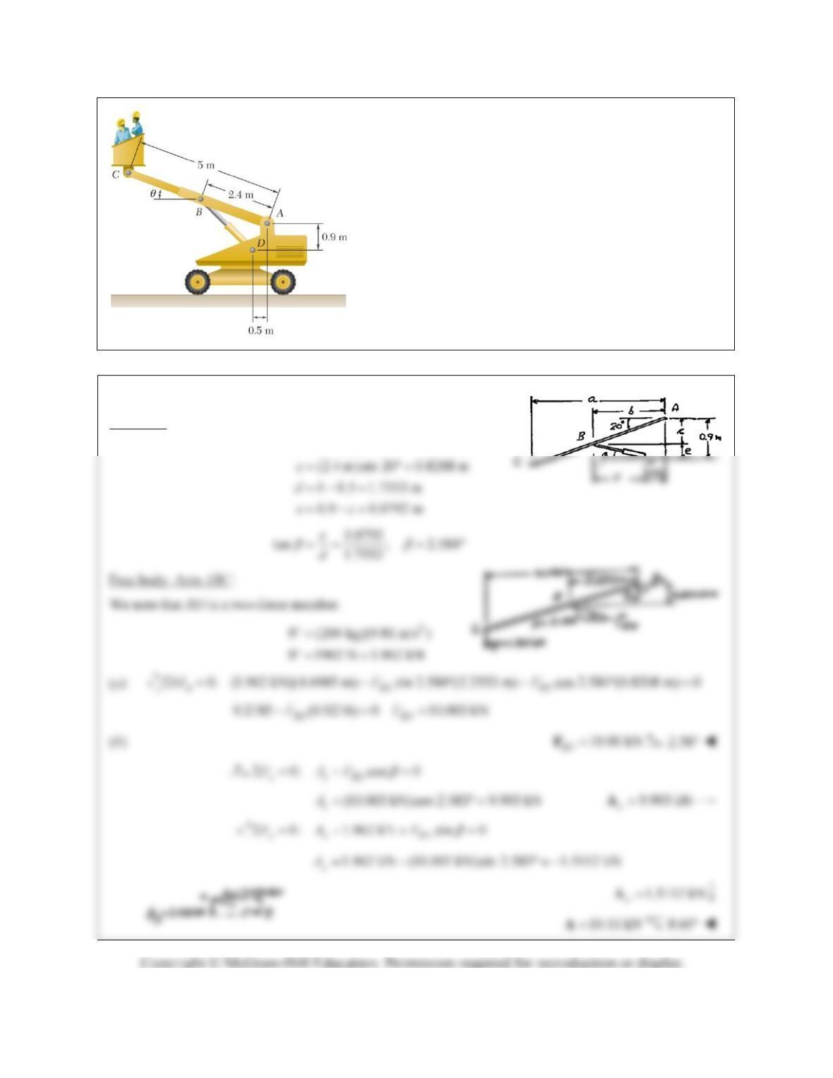
PROBLEM 6.156
The telescoping arm ABC of Prob. 6.155 can be lowered
until end C is close to the ground, so that workers can easily
board the platform. For the position when
= 20,
determine (a) the force exerted at B by the single hydraulic
cylinder BD, (b) the force exerted on the supporting carriage
at A.
SOLUTION
Geometry:
(5 m)cos 20 4.6985 m
(2.4 m) cos 20 2.2552 m
a
b
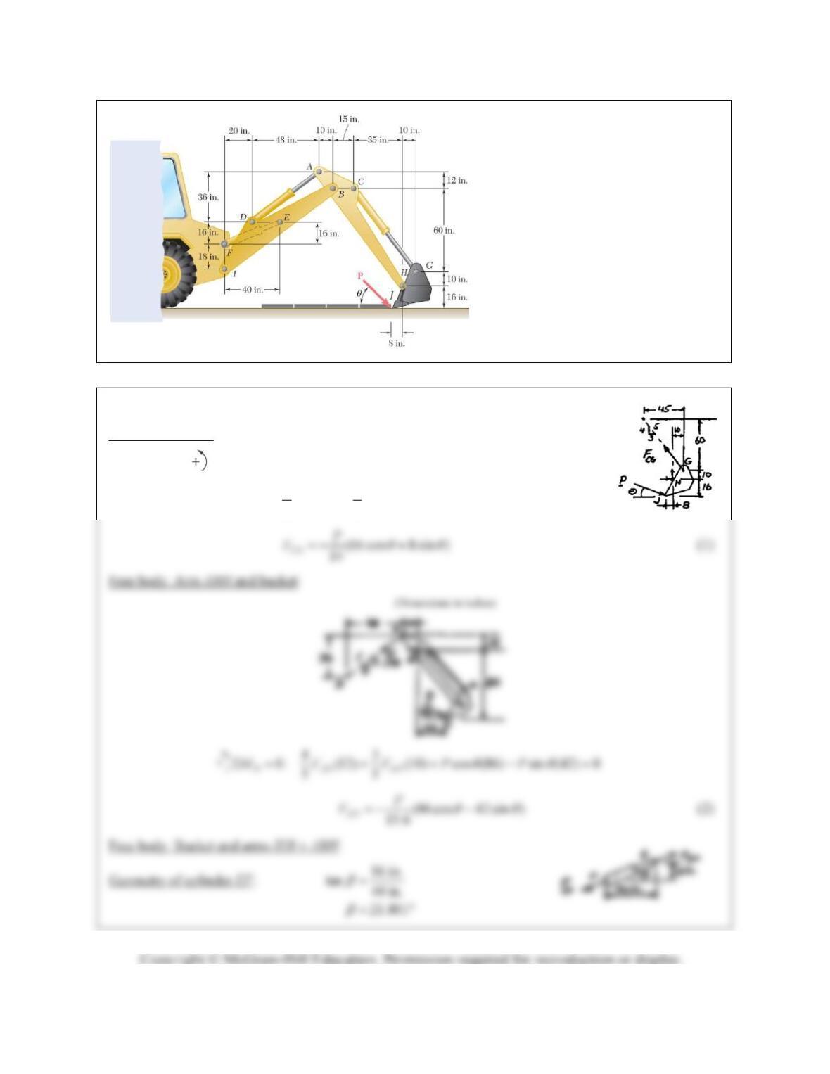
PROBLEM 6.157
The motion of the backhoe bucket
shown is controlled by the hydraulic
cylinders AD, CG, and EF. As a result
of an attempt to dislodge a portion of a
slab, a 2-kip force
P
is exerted on the
bucket teeth at J. Knowing that
45,
determine the force exerted by each
cylinder.
SOLUTION
Free body: Bucket:
0:
H
M
(Dimensions in inches)
43
(10) (10) cos (16) si n (8) 0
55
CG CG
FFP P
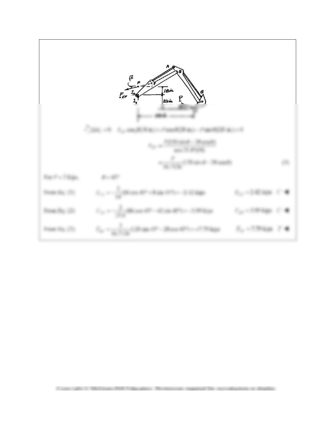
PROBLEM 6.157 (Continued)

PROBLEM 6.158
Solve Problem 6.157 assuming that the
2-kip force
P
acts horizontally to the
right (
0).
PROBLEM 6.157
The motion of the
backhoe bucket shown is controlled by
the hydraulic cylinders AD, CG, and
EF. As a result of an attempt to
dislodge a portion of a slab, a 2-kip
force
P
is exerted on the bucket teeth at
J. Knowing that
45, determine the
force exerted by each cylinder.
SOLUTION
Free body: Bucket:
0:
H
M
(Dimensions in inches)
43
(10) (10) cos (16) si n (8) 0
55
CG CG
FFP P
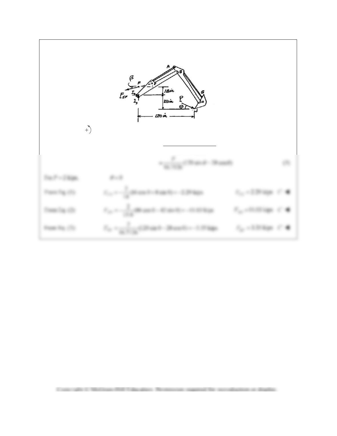
PROBLEM 6.158 (Continued)
0: cos (18 in.) cos (28 in.) sin (120 in.) 0
IEF
MF P P
(120 sin 28 cos )
cos 21.8 (18)
EF
P
F
PROBLEM 6.159
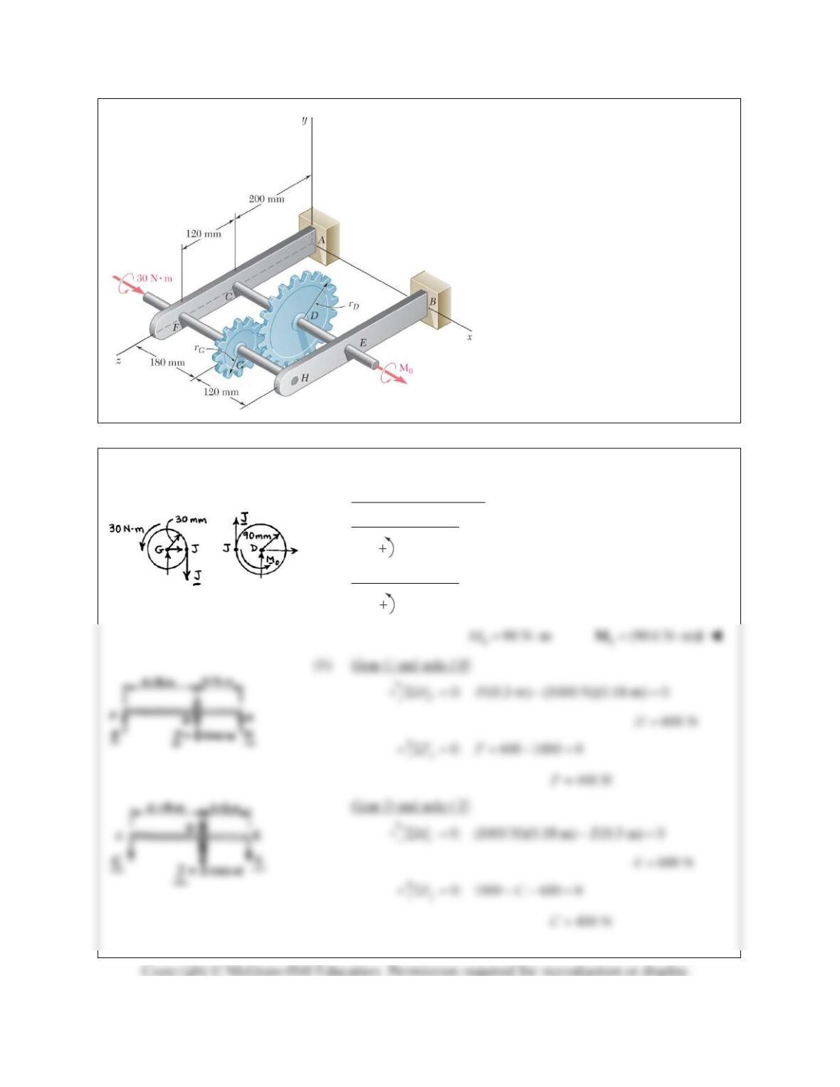
The gears D and G are rigidly attached
to shafts that are held by frictionless
bearings. If r
D
90 mm and r
G
30
mm, determine (a) the couple
M0
that
must be applied for equilibrium, (b) the
reactions at A and B.
SOLUTION
(a) Projections on yz plane.
Free body: Gear G:
0: 30 N m (0.03 m) 0; 1000 N
G
MJJ
Free body: Gear D:
0
0: (1000 N)(0.09 m) 0
D
MM
PROBLEM 6.159 (Continued)
Free body: Bracket AE:
0: 400 400 0
y
FA
0
A
B
B
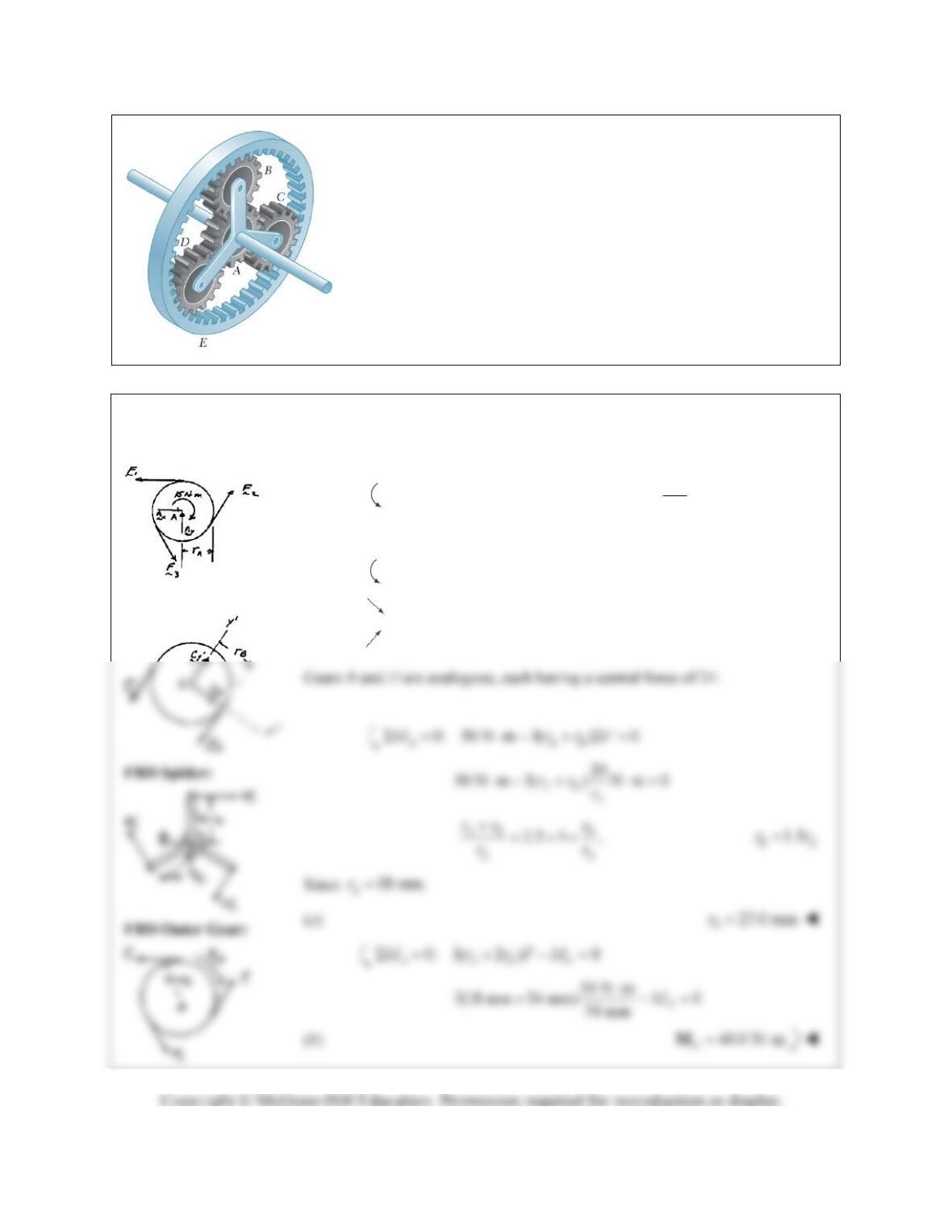
PROBLEM 6.160
In the planetary gear system shown, the radius of the central gear A is
a 18 mm, the radius of each planetary gear is b, and the radius of the
outer gear E is (a 2b). A clockwise couple of magnitude M
A
10 N m
is applied to the central gear A and a counterclockwise couple of
magnitude M
S
50 N m is applied to the spider BCD. If the system is
to be in equilibrium, determine (a) the required radius b of the
planetary gears, (b) the magnitude M
E
of the couple that must be
applied to the outer gear E.
SOLUTION
FBD Central Gear:
FBD Gear
C
:
By symmetry,
123
FF FF
10
0: 3( ) 10 N m 0, N m
3
AA
A
MrF F
r
44
0: ( ) 0,
CB
MrFF FF
0: 0
xx
FC
0: 2 0, 2
yy y
FCF CF
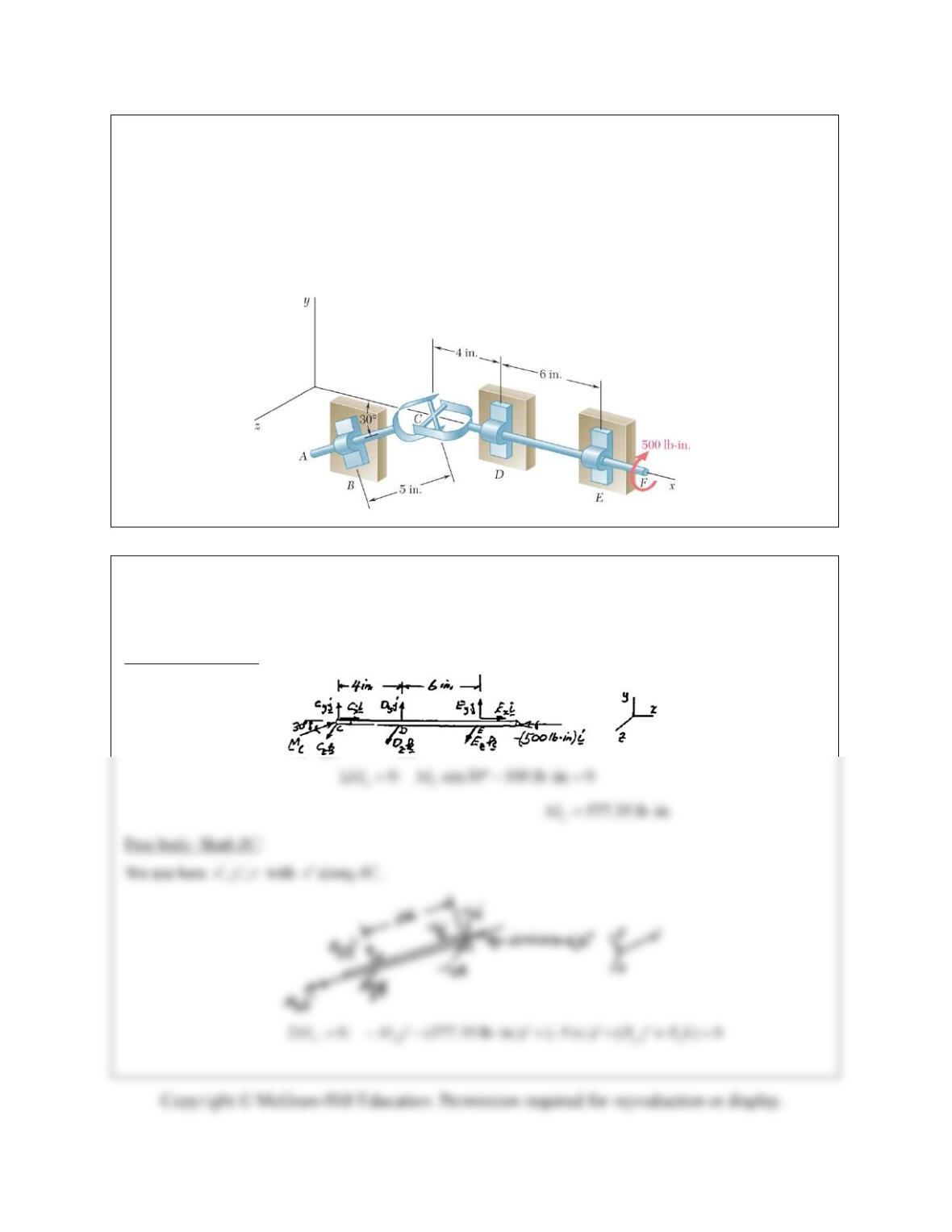
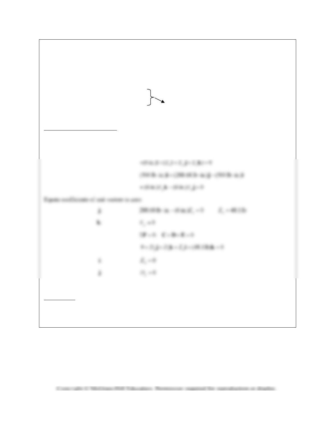
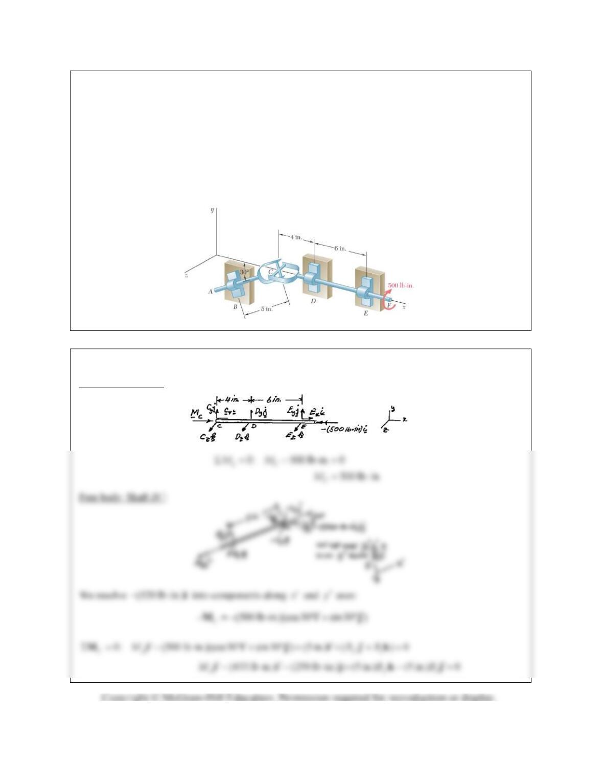
PROBLEM 6.161*
Two shafts AC and CF, which lie in the vertical xy plane, are connected by a universal joint at C. The
bearings at B and D do not exert any axial force. A couple of magnitude 500 lb in. (clockwise when
viewed from the positive x-axis) is applied to shaft CF at F. At a time when the arm of the crosspiece
attached to shaft CF is horizontal, determine (a) the magnitude of the couple that must be applied to shaft
AC at A to maintain equilibrium, (b) the reactions at B, D, and E. (Hint: The sum of the couples exerted
on the crosspiece must be zero.)
SOLUTION
We recall from Figure 4.10 that a universal joint exerts on members it connects a force of unknown
direction and a couple about an axis perpendicular to the crosspiece.
Free body: Shaft DF:
PROBLEM 6.161* (Continued)
Equate coefficients of unit vectors to zero:
i: 577.35 lb in. 0
A
M
577.35 lb in.
A
M
j: 0
z
B 577 lb in.
A
M
k: 0
y
B 0B
0B
0: 0, since 0,BC B F 0C
Return to free body of shaft DF.
0
D
M (Note that 0C
and 577.35 lb in.
C
M
)
(577.35 lb in.)(cos30 sin 30 ) (500 lb in.)
ij i
k: 48.1 lb 0
z
D
48.1 lb
z
D
Reactions are: 0
B
(48.1 lb)Dk
(48.1 lb)Ek
PROBLEM 6.162*
Solve Problem 6.161 assuming that the arm of the crosspiece attached to shaft CF is vertical.
PROBLEM 6.161
Two shafts AC and CF, which lie in the vertical xy plane, are connected by a universal
joint at C. The bearings at B and D do not exert any axial force. A couple of magnitude 500 lb · in.
(clockwise when viewed from the positive x-axis) is applied to shaft CF at F. At a time when the arm of
the crosspiece attached to shaft CF is horizontal, determine (a) the magnitude of the couple that must be
applied to shaft AC at A to maintain equilibrium, (b) the reactions at B, D, and E. (Hint: The sum of the
couples exerted on the crosspiece must be zero.)
SOLUTION
Free body: Shaft DF.
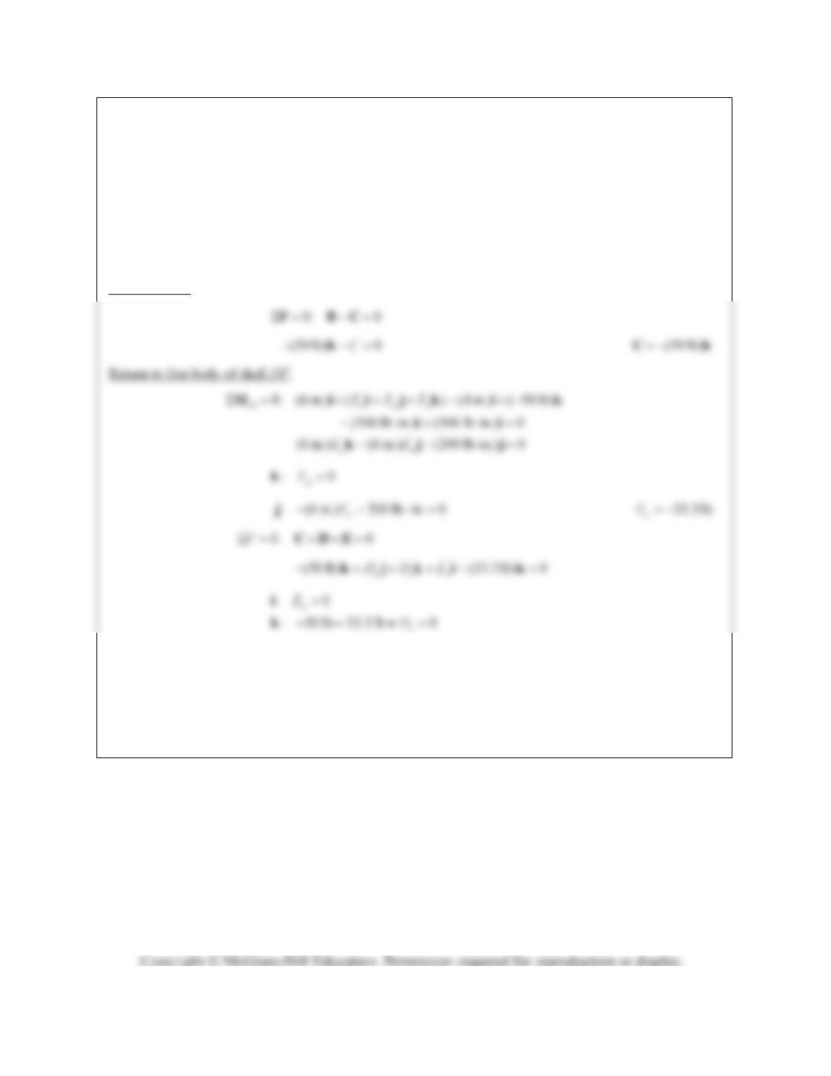
PROBLEM 6.162* (Continued)
Equate to zero coefficients of unit vectors:
: 433 lb in. 0
A
M
i 433 lb in.
A
M
:250lbin.(5in.) 0
z
B
j 50 lb
z
B
:0
ykB
Reactions at B. (50 lb)Bk
83.3 lb
z
D
Reactions are (50 lb)Bk
(83.3 lb)Dk
(33.3 lb)Ek
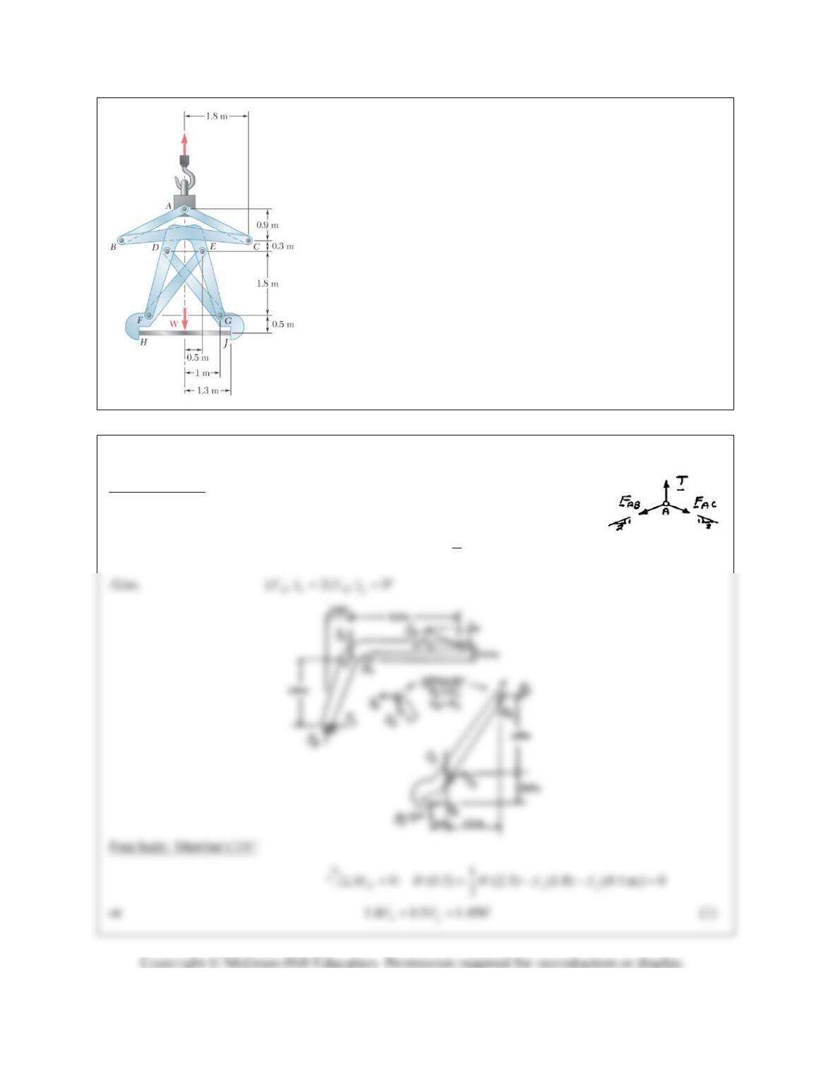
PROBLEM 6.163*
The large mechanical tongs shown are used to grab and lift a
thick 7500-kg steel slab HJ. Knowing that slipping does not
occur between the tong grips and the slab at H and J, determine
the components of all forces acting on member EFH. (Hint:
Consider the symmetry of the tongs to establish relationships
between the components of the force acting at E on EFH and the
components of the force acting at D on DGJ.)
SOLUTION
Free body: Pin A: 2
(7500 kg)(9.81 m/s ) 73.575 kNTW mg
0: ( ) ( )
1
0: ( ) ( ) 2
xABxACx
yAByACy
FFF
FFFW
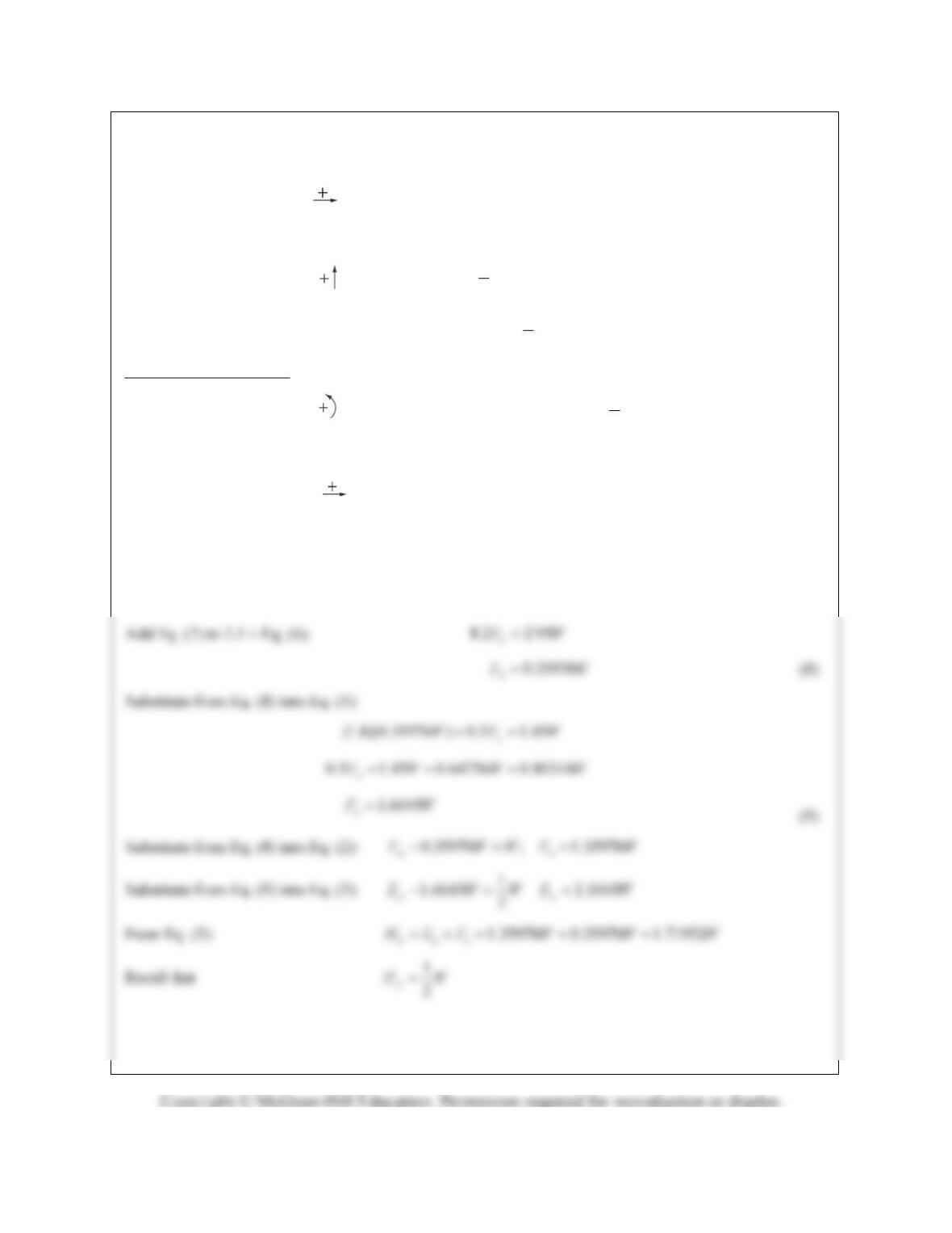
PROBLEM 6.163* (Continued)
0: 0
xxx
FDFW
or
xx
EFW
(2)
1
0: 0
2
yyy
FFDW
or
1
2
yy
EF W
(3)
Free body: Member EFH:
1
0: (1.8) (1.5) (2.3) (1.8 m) 0
2
Ex y x
MFFH W
or
1.8 1.5 2.3 0.9
xy x
FF H W
(4)
0: 0
xxxx
FEFH
or
xx x
EFH
(5)
Subtract Eq. (2) from Eq. (5):
2
xx
FHW
(6)
Subtract Eq. (4) from 3 (1):
3.6 5.25 2.3
xx
FWH
(7)
PROBLEM 6.163* (Continued)
Since all expressions obtained are positive, all forces are directed as shown on the free-body diagrams.
Substitute
73.575 kNW