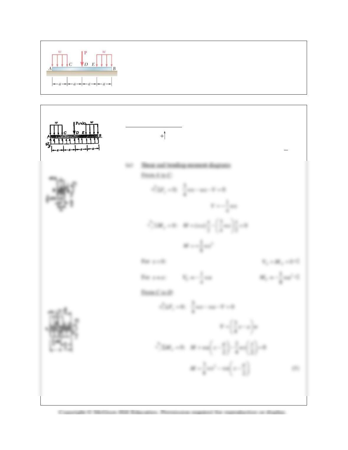
PROBLEM 7.43
Assuming the upward reaction of the ground on beam AB to be
uniformly distributed and knowing that P =wa, (a) draw the shear and
bending-moment diagrams, (b) determine the maximum absolute values
of the shear and bending moment.
SOLUTION
Free body: Entire beam
0: (4 ) 2 0
yg
F w a wa waΣ= − − =
3
4
g
ww=
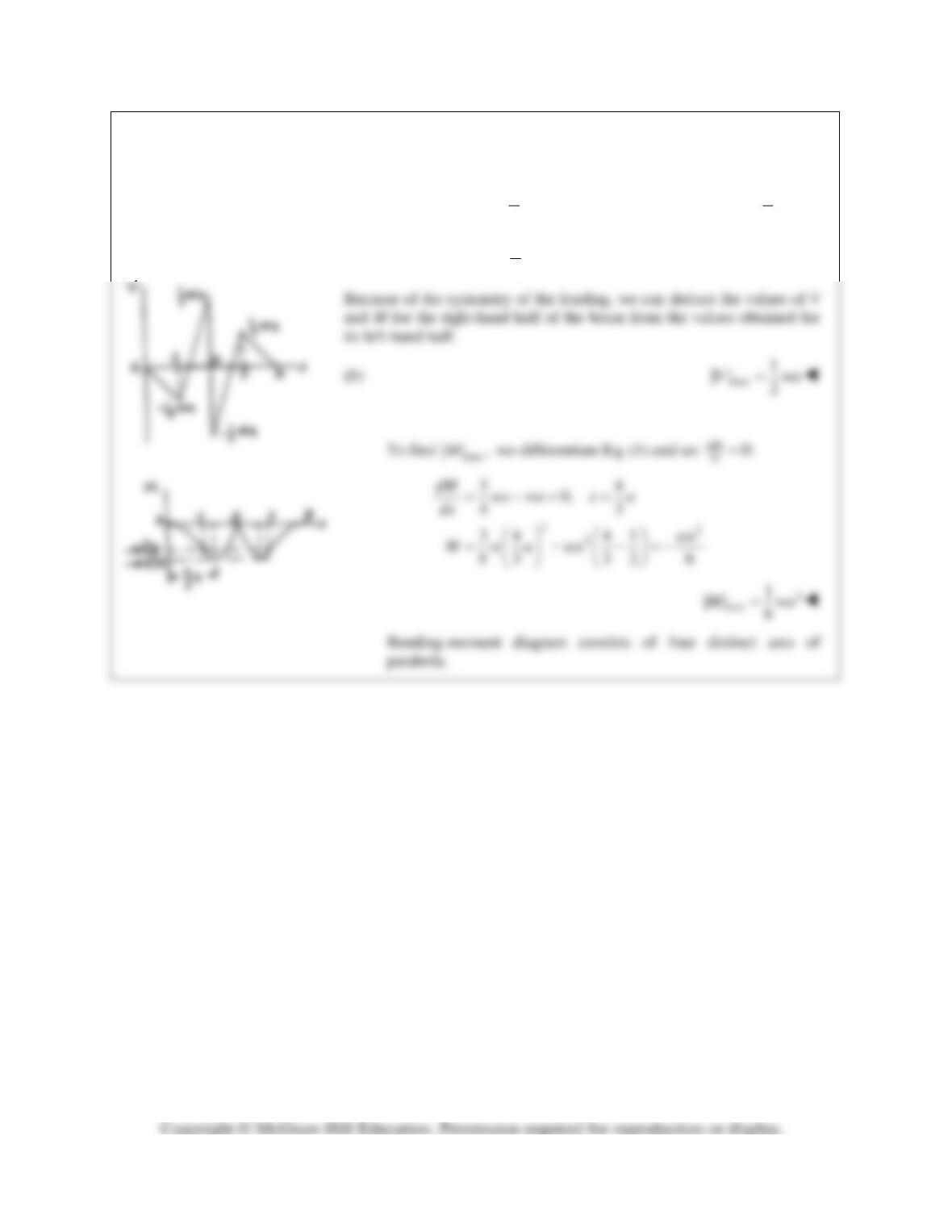
PROBLEM 7.43 (Continued)
For
:xa=
1
4
C
V wa= −
2
1
8
C
M wa= −
For
2:xa=
1
2
D
V wa= +
0
D
M=
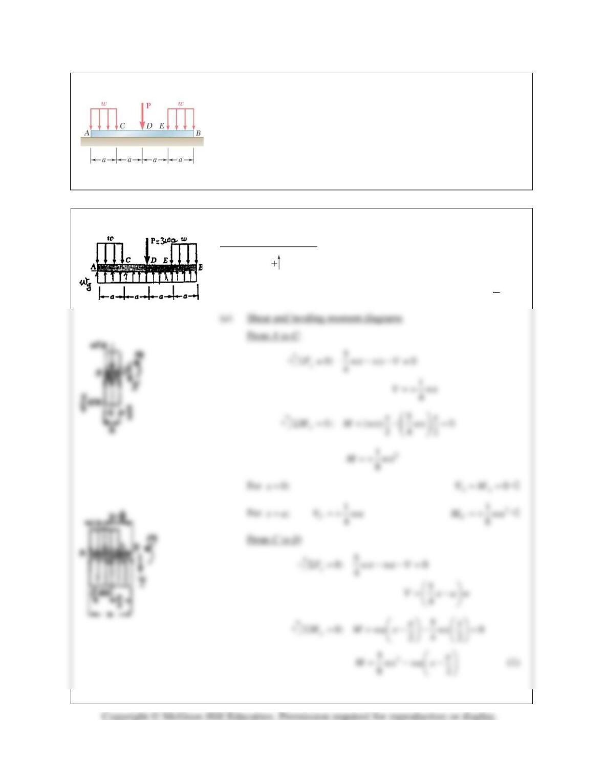
PROBLEM 7.44
Solve Problem 7.43 knowing that P=3wa.
PROBLEM 7.43 Assuming the upward reaction of the ground on beam
AB to be uniformly distributed and knowing that P =wa, (a) draw the
shear and bending-moment diagrams, (b) determine the maximum
absolute values of the shear and bending moment.
SOLUTION
Free body: Entire beam
0: (4 ) 2 3 0
yg
F w a wa waΣ= − − =
5
4
g
ww=
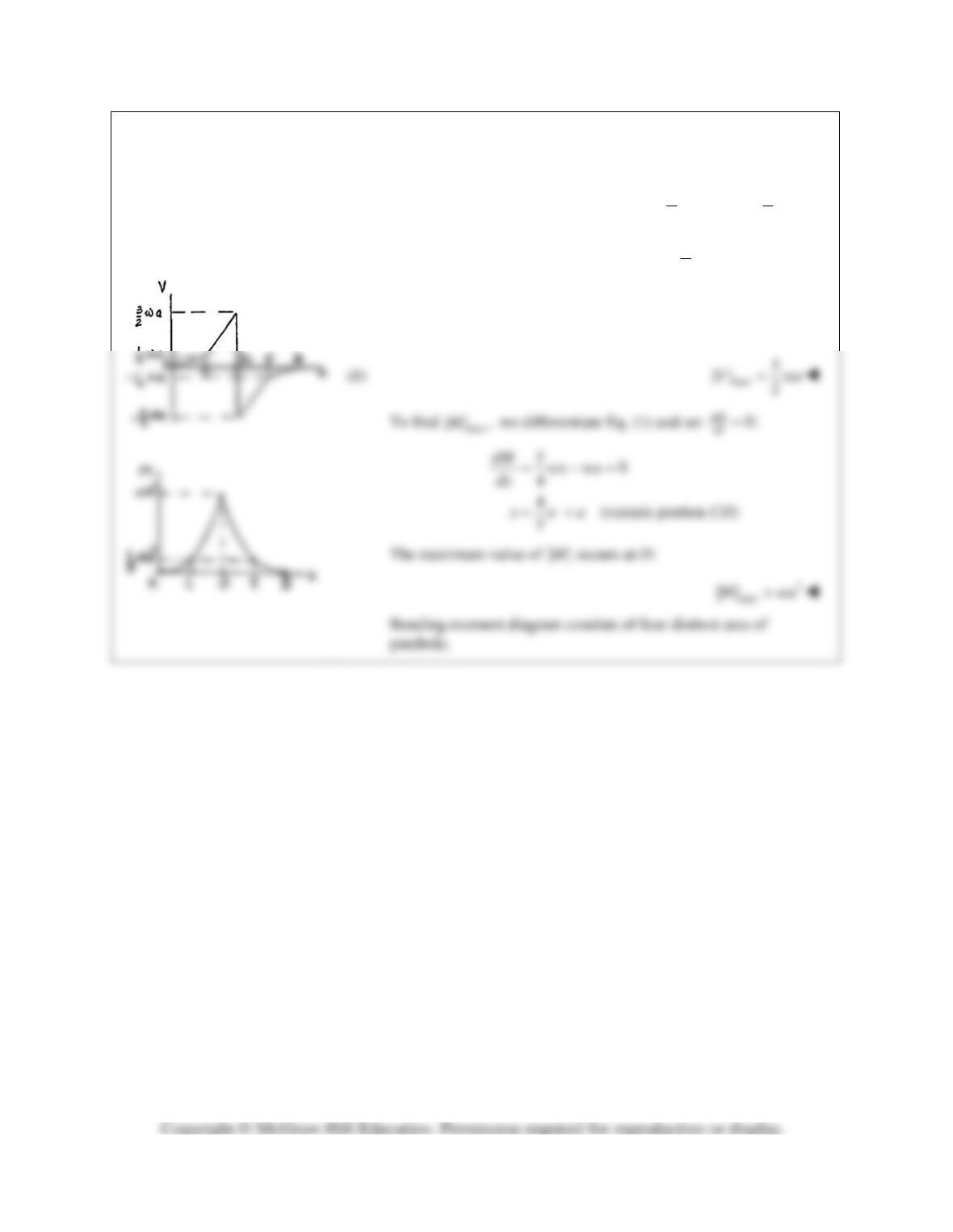
PROBLEM 7.44 (Continued)
For
:xa=
1,
4
C
V wa= +
2
1
8
C
M wa= +
For
2:xa=
3,
2
D
V wa= +
2
D
M wa= +
Because of the symmetry of the loading, we can deduce the
values of V and M for the right-hand half of the beam from the
values obtained for its left-hand half.
PROBLEM 7.45
Assuming the upward reaction of the ground on beam AB to be
uniformly distributed, (a) draw the shear and bending-moment diagrams,
(b) determine the maximum absolute values of the shear and bending
moment.
SOLUTION
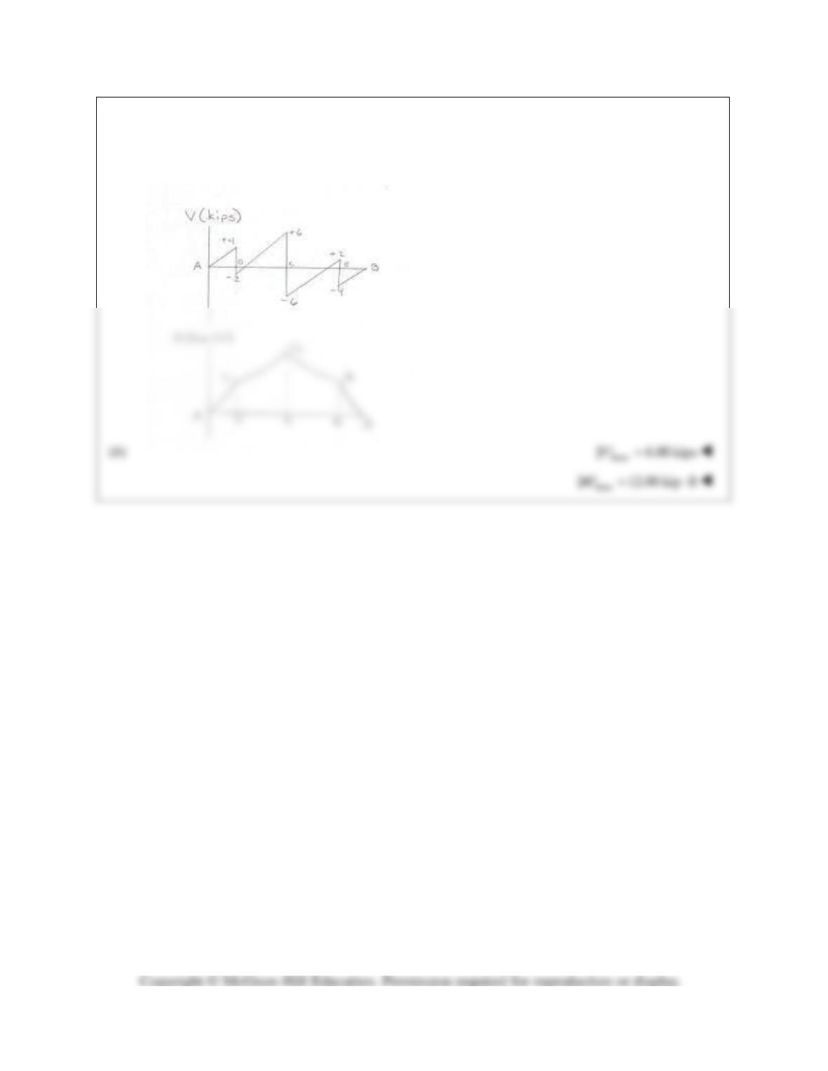
(a) For equilibrium,
0: 6 12 6 (12 ft)=0
y
FwΣ = −− −+
2.0 kips/ftw=
Along AD:
PROBLEM 7.45 (Continued)
Complete diagrams using symmetry.
PROBLEM 7.46
Solve Prob. 7.45 assuming that the 12-kip load has been
removed.
PROBLEM 7.45 Assuming the upward reaction of the ground on beam
AB to be uniformly distributed, (a) draw the shear and bending–moment
diagrams, (b) determine the maximum absolute values of the shear and
bending moment.
SOLUTION
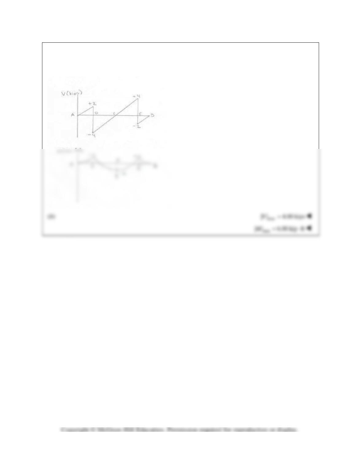
For equilibrium,
0: 12 6 6 0
yg
FwΣ = −−=
1 kip/ft
g
w=
(a) Shear and bending moment
PROBLEM 7.46 (Continued)
PROBLEM 7.47
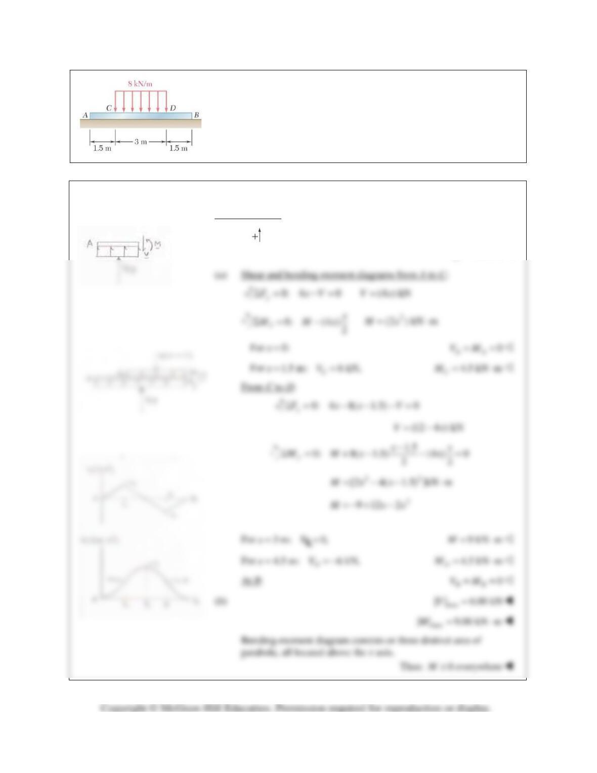
Assuming the upward reaction of the ground on beam AB to be
uniformly distributed, (a) draw the shear and bending–moment
diagrams,(b) determine the maximum absolute values of the shear and
bending moment.
SOLUTION
For equilibrium,
0: (6 m) (8 kN/m)(3 m) 0
yg
FwΣ= − =
4 kN/m
g
w=
PROBLEM 7.48
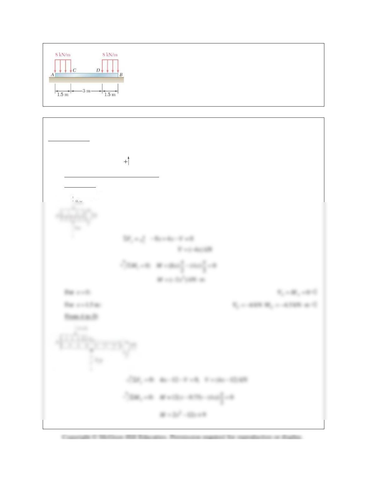
Assuming the upward reaction of the ground on beam AB to be
uniformly distributed, (a) draw the shear and bending-moment diagrams,
(b) determine the maximum absolute values of the shear and bending
moment.
SOLUTION
For equilibrium,
0: (6 m) (8 kN/m)(3 m) 0
yg
FwΣ= − =
4 kN/m
g
w=
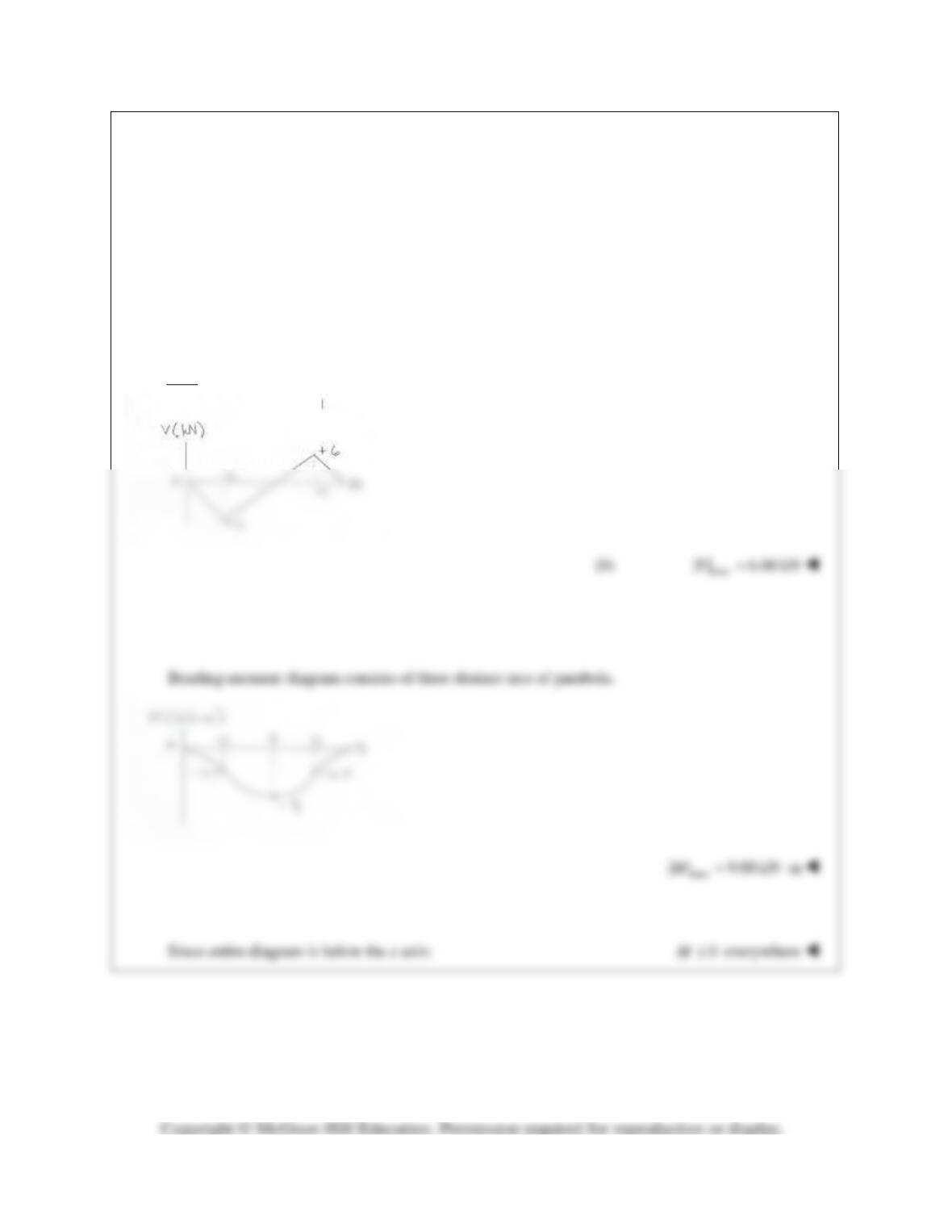
(a) Shear and bending-moment diagrams.
From A to C:
PROBLEM 7.48 (Continued)
For
3 m:x=
0,V=
9.00 kN mM=−⋅
For
4.5 m:x=
6 kN,
D
V= +
4.50 kN m
D
M=−⋅
At B:
0
BB
VM= =
PROBLEM 7.49
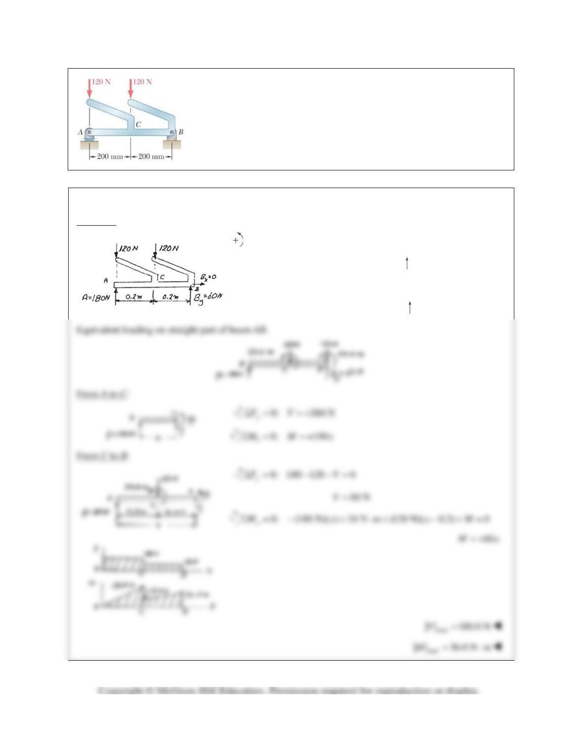
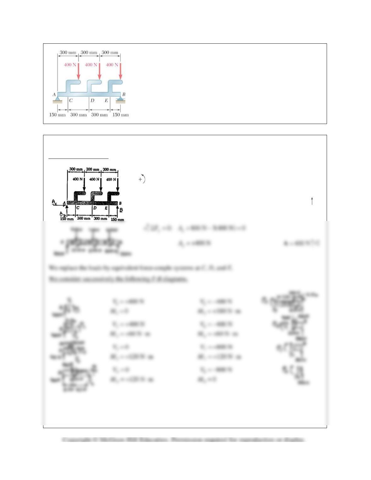
Draw the shear and bending-moment diagrams for the beam AB, and
determine the maximum absolute values of the shear and bending moment.
SOLUTION
Reactions:
0: (0.4) (120)(0.2) 0
Ay
MBΣ= − =
60 N
y
=B
0:
x
FΣ=
0
x=B
0:
y
FΣ=
180 N=A
PROBLEM 7.50
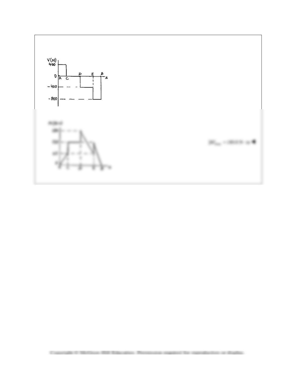
Draw the shear and bending-moment diagrams for the beam AB, and
determine the maximum absolute values of the shear and bending
moment.
SOLUTION
Free body: Entire beam
0: (0.9 m) (400 N)(0.3 m) (400 N)(0.6 m)
(400 N)(0.9 m) 0
A
MBΣ= − −
−=
800 NB= +
800 N=B
0: 0
xx
FAΣ= =
PROBLEM 7.50 (Continued)
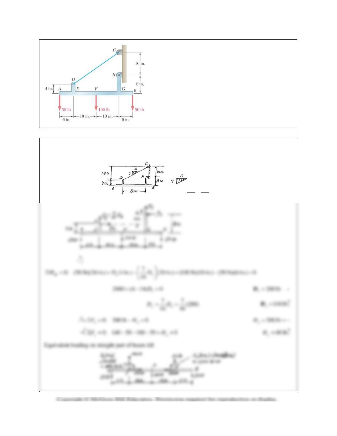
(b)
max
| | 800 NV=
PROBLEM 7.51
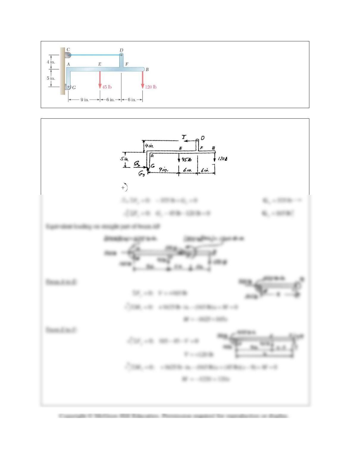
Draw the shear and bending–moment diagrams for the
beam AB, and determine the maximum absolute values of
the shear and bending moment.
SOLUTION
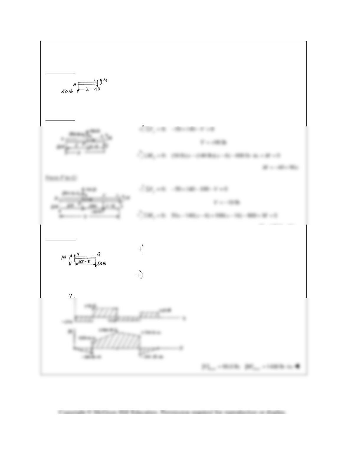
Slope of cable CD is
7 10
yx
DD
∴=
PROBLEM 7.51 (Continued)
From A to E:
0: 50 lb
y
FVΣ= =−
1
0: 50M MxΣ= =−
From E to F:
1560 10Mx= −
From G to B:
0: 50 0
y
FVΣ= −=
50 lbV=
4
0: (50)(32 ) 0MM xΣ = −− −=
1600 50Mx=−+
PROBLEM 7.52
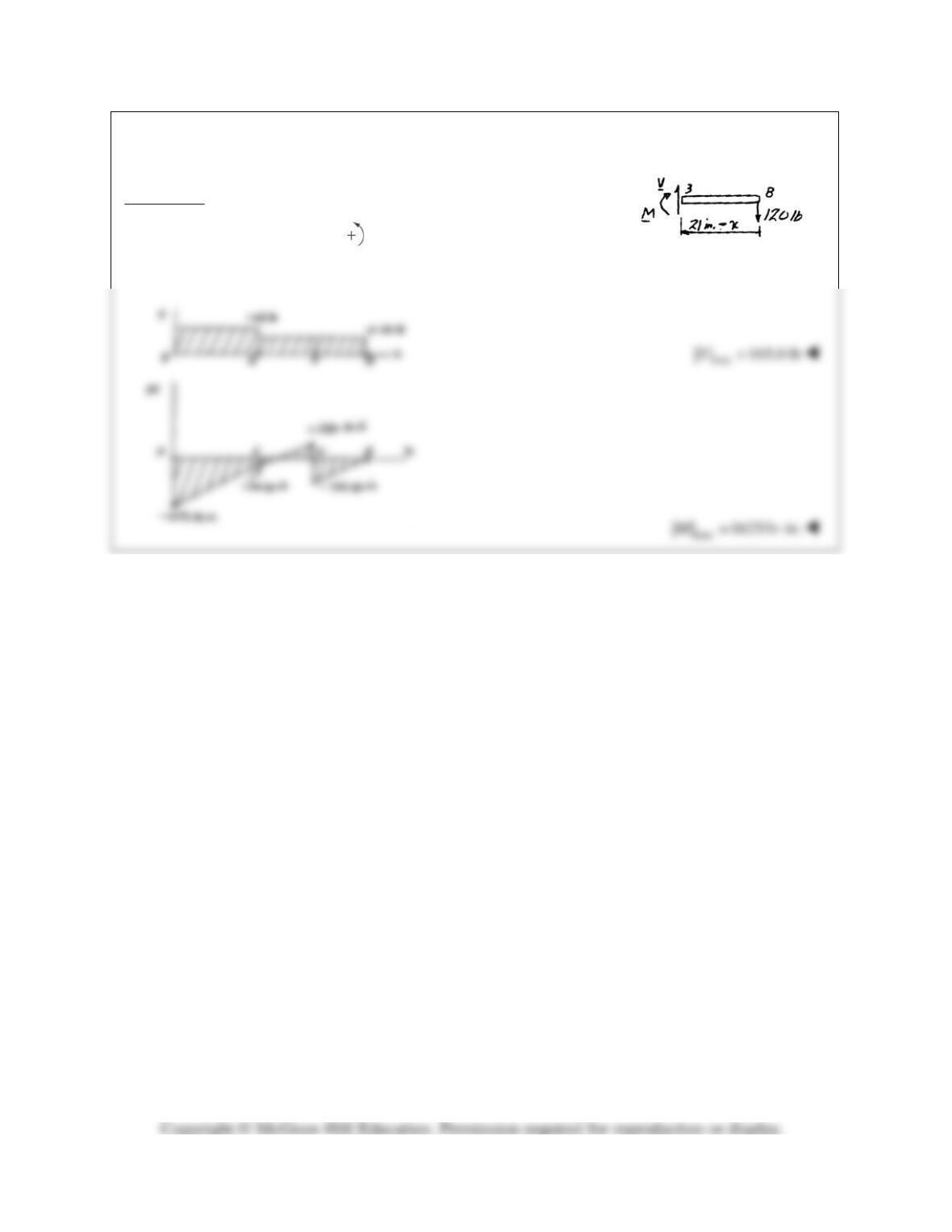
Draw the shear and bending–moment diagrams for the
beam AB, and determine the maximum absolute values
of the shear and bending moment.
SOLUTION
0: (9 in.) (45 lb)(9 in.) (120 lb)(21in.) 0
G
FTΣ= − − =
325 lbT=
PROBLEM 7.52 (Continued)
From F to B:
0 120 lb
y
FVΣ= =+
30: (120)(21 ) 0M xMΣ = − −− =
2520 120Mx=−+
PROBLEM 7.53
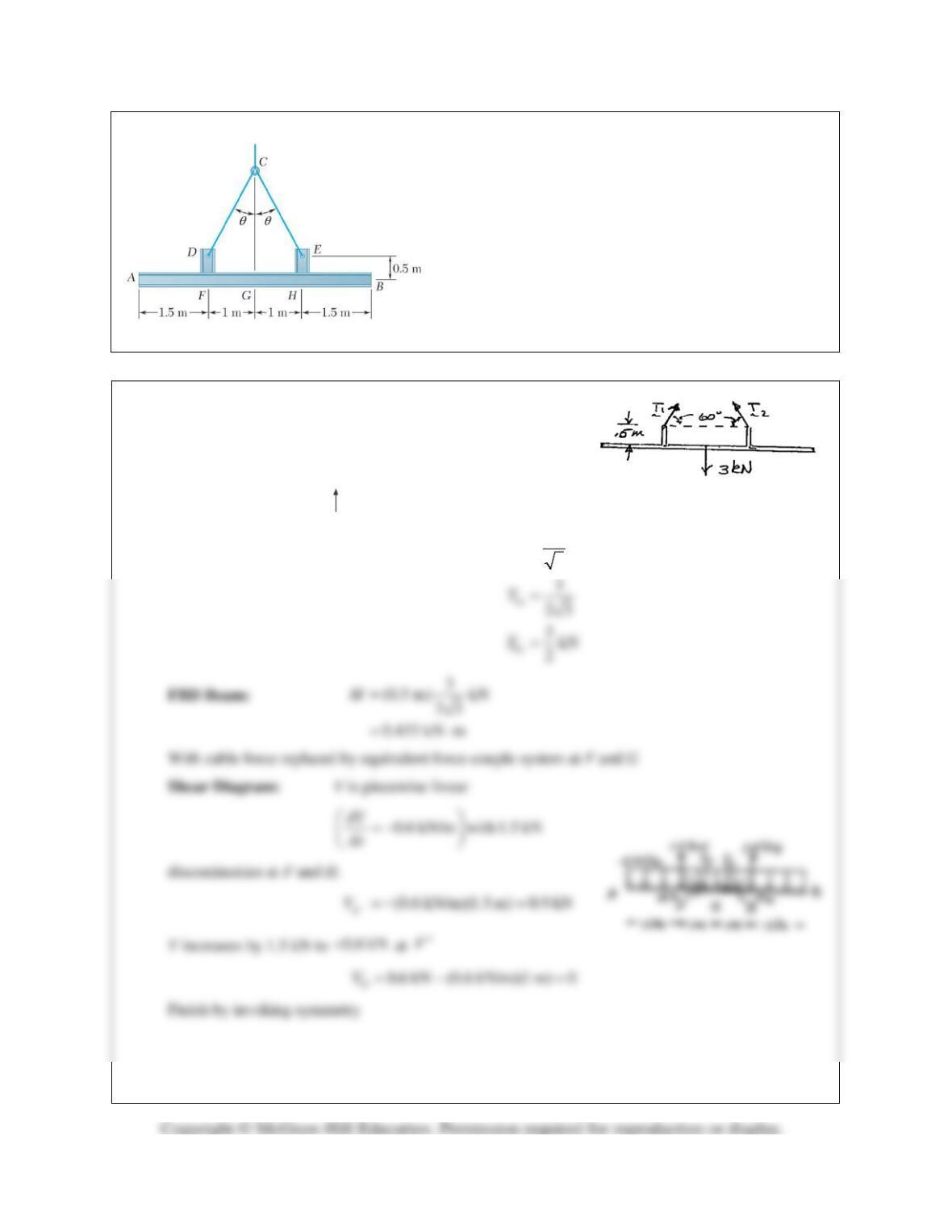
Two small channel sections DF and EH have been
welded to the uniform beam AB of weight W= 3 kN to
form the rigid structural member shown. This member is
being lifted by two cables attached at D and E. Knowing
that
θ
= 30° and neglecting the weight of the channel
sections, (a) draw the shear and bending-moment
diagrams for beam AB, (b) determine the maximum
absolute values of the shear and bending moment in the
beam.
SOLUTION
FBD Beam
+
channels:
(a) By symmetry:
12
TT T= =
0: 2 sin 60 3 kN 0
y
FTΣ = °− =
PROBLEM 7.53 (Continued)
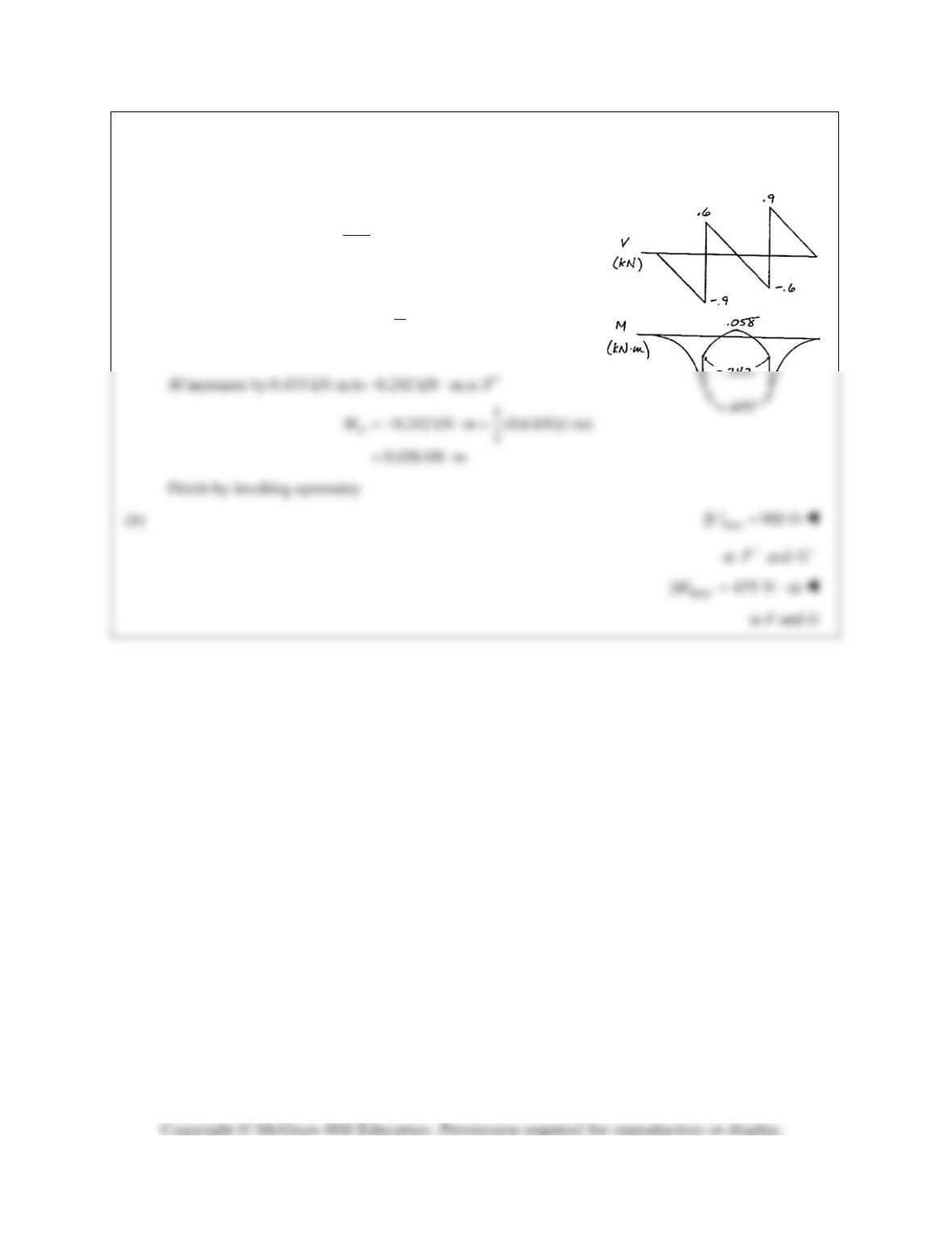
Moment diagram: M is piecewise parabolic
decreasing with
dM V
dx
with discontinuities of .433 kN at F and H.
1(0.9 kN)(1.5 m)
2
0.675 kN m
F
M−= −
=−⋅