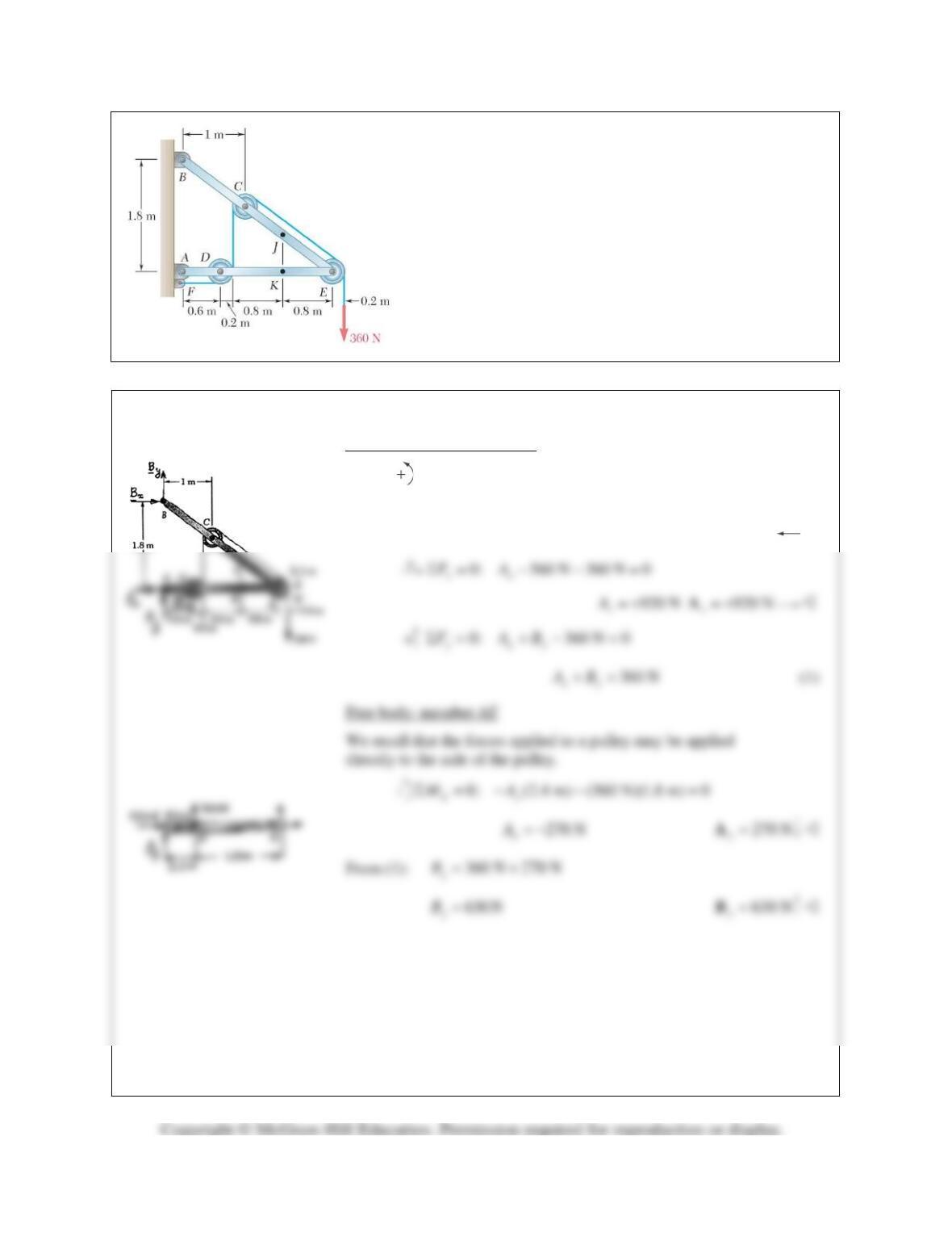
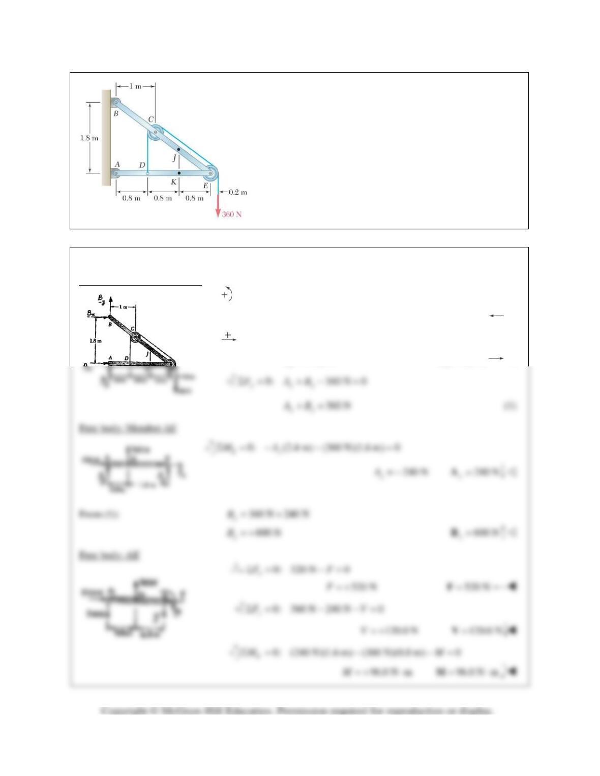
PROBLEM 7.16
Knowing that the radius of each pulley is 200 mm and
neglecting friction, determine the internal forces at Point K of
the frame shown.
SOLUTION
Free body: frame and pulleys
0: (1.8 m) (360 N)(0.2 m)
(360 N)(2.6 m) 0
Ax
MBΣ=− −
−=
560 N
x
B= −
560 N
x=B
PROBLEM 7.16 (Continued)
Free body: AK
0: 920 N 360 N 0
x
FFΣ= − −=
560 NF= +
560 N=F
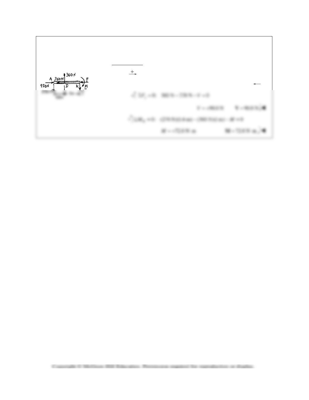
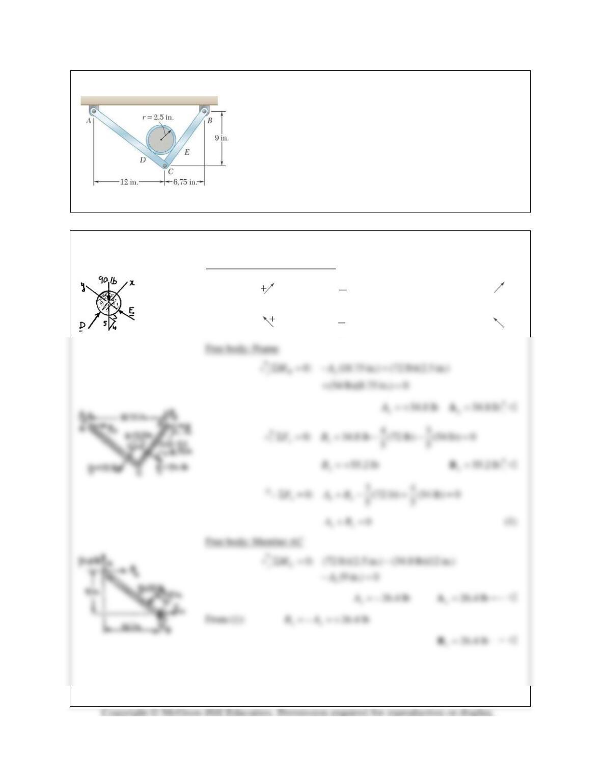
PROBLEM 7.17
A 5–in.–diameter pipe is supported every 9 ft by a small frame
consisting of two members as shown. Knowing that the combined
weight of the pipe and its contents is 10 lb/ft and neglecting the
effect of friction, determine the magnitude and location of the
maximum bending moment in member AC.
SOLUTION
Free body: 10-ft section of pipe
4
0: (90 lb) 0
5
x
FDΣ= − =
72 lb=D
3
0: (90 lb) 0
5
y
FEΣ= − =
54 lb=E
PROBLEM 7.17 (Continued)
Free body: Portion AJ
For 12.5 in. ( ) :x AJ AD≤≤
34
0: (26.4 lb) (34.8 lb) 0
55
J
M x xMΣ = − +=
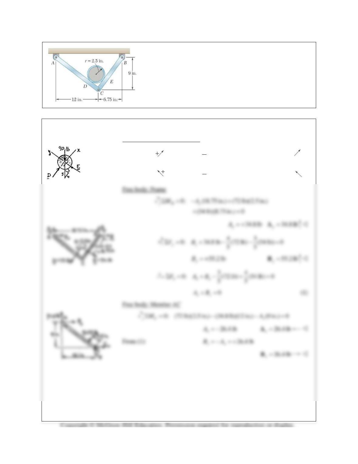
PROBLEM 7.18
For the frame of Problem 7.17, determine the magnitude and
location of the maximum bending moment in member BC.
PROBLEM 7.17 A 5–in.–diameter pipe is supported every 9 ft by
a small frame consisting of two members as shown. Knowing that
the combined weight of the pipe and its contents is 10 lb/ft and
neglecting the effect of friction, determine the magnitude and
location of the maximum bending moment in member AC.
SOLUTION
Free body: 10-ft section of pipe
4
0: (90 lb) 0
5
x
FDΣ= − =
72 lb=D
3
0: (90 lb) 0
5
y
FEΣ= − =
54 lb=E
PROBLEM 7.18 (Continued)
Free body: Portion BK
For 8.75 in.( ):x BK BE≤≤
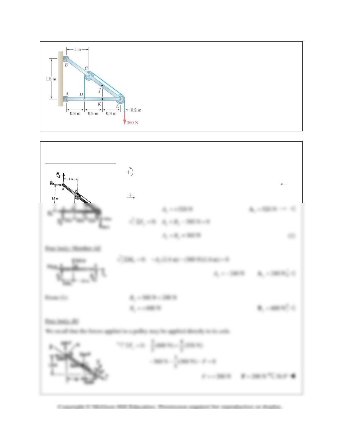
PROBLEM 7.19
Knowing that the radius of each pulley is 200 mm and
neglecting friction, determine the internal forces at Point J of
the frame shown.
SOLUTION
Free body: Frame and pulleys
0: (1.8 m) (360 N)(2.6 m) 0
Ax
MBΣ= − − =
520 N
x
B= −
520 N
x=B
0: 520 N 0
xx
FAΣ= − =
PROBLEM 7.19 (Continued)
434
0: (600 N) (520 N) (360 N) 0
555
x
FVΣ= − − +=
120.0 NV= +
120.0 N=V
53.1°
PROBLEM 7.20
Knowing that the radius of each pulley is 200 mm and
neglecting friction, determine the internal forces at Point K of
the frame shown.
SOLUTION
Free body: Frame and pulleys
0: (1.8 m) (360 N)(2.6 m) 0
Ax
MBΣ= − − =
520 N
x
B= −
520 N
x=B
0: 520 N 0
xx
FAΣ= − =
520 N
x
A= +
520 N
x
=A
PROBLEM 7.21
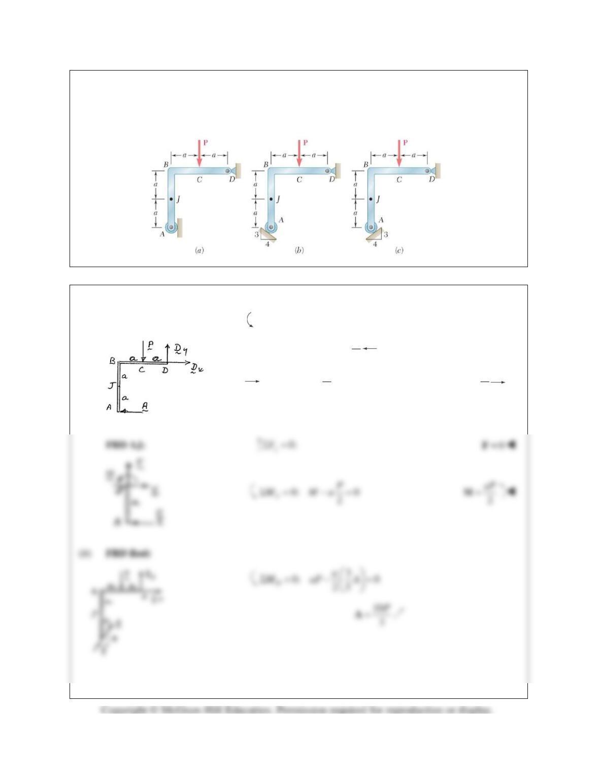
A force P is applied to a bent rod that is supported by a roller and a pin and bracket. For each of the three
cases shown, determine the internal forces at Point J.
SOLUTION
(a) FBD Rod:
0: 2 0
D
M aP aAΣ= − =
2
P
=A
0: 0
2
x
P
FVΣ= −=
2
P
=V
PROBLEM 7.21 (Continued)
FBD AJ:
4 10
0: 0
53
x
P
FVΣ = −=
8
3
P
=V
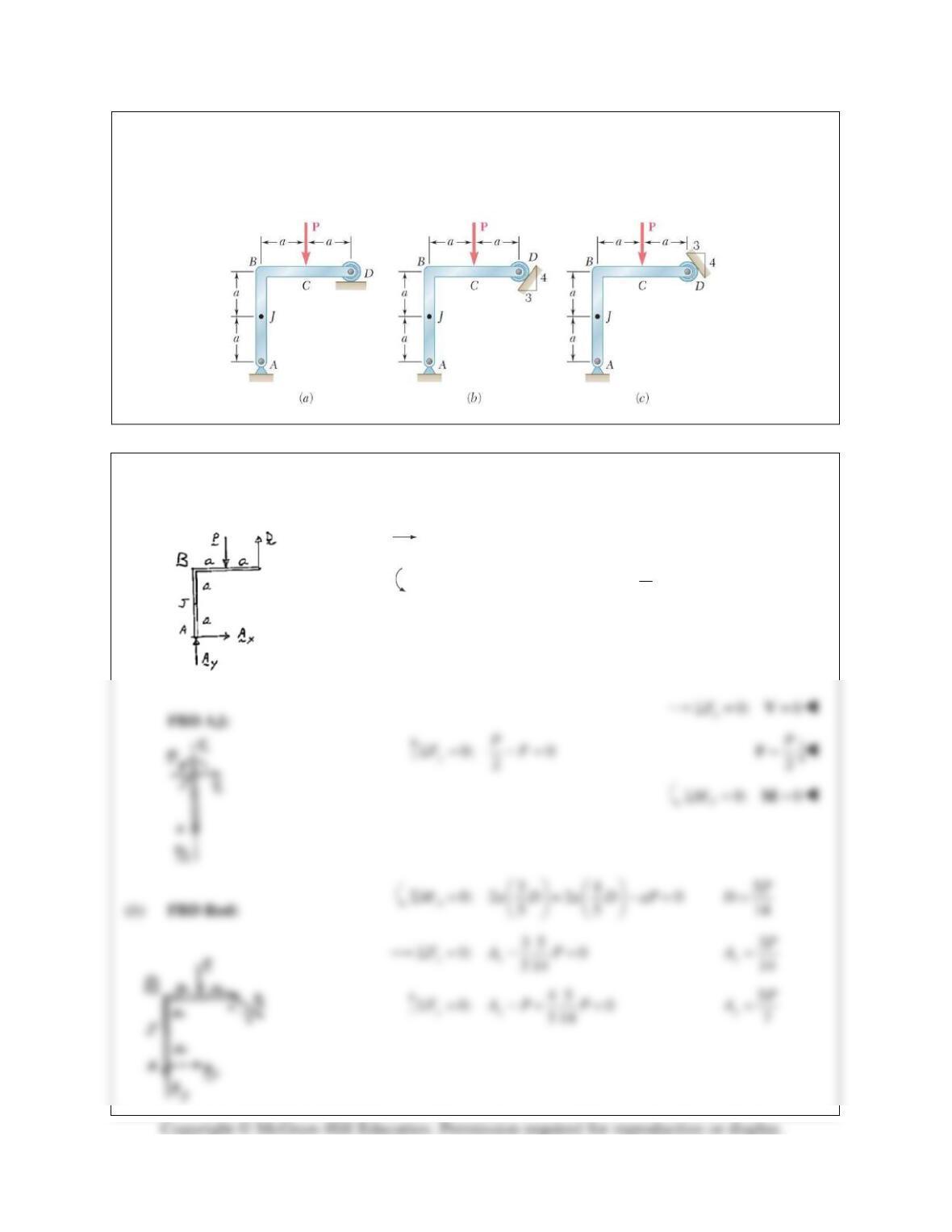
PROBLEM 7.22
A force P is applied to a bent rod that is supported by a roller and a pin and bracket. For each of the three
cases shown, determine the internal forces at Point J.
SOLUTION
(a) FBD Rod:
0: 0
xx
FAΣ= =
0: 2 0 2
D yy
P
M aP A AΣ= − = =
FBD AJ:
PROBLEM 7.22 (Continued)
0:
x
FΣ=
30
14 PV−=
3
14
P
=V
0:
y
FΣ=
50
7
PF−=
5
7
P
=F
3
0: 0
14
J
P
M aMΣ = −=
3
14 aP=M
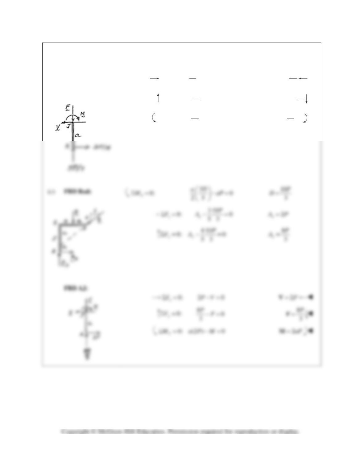
PROBLEM 7.23
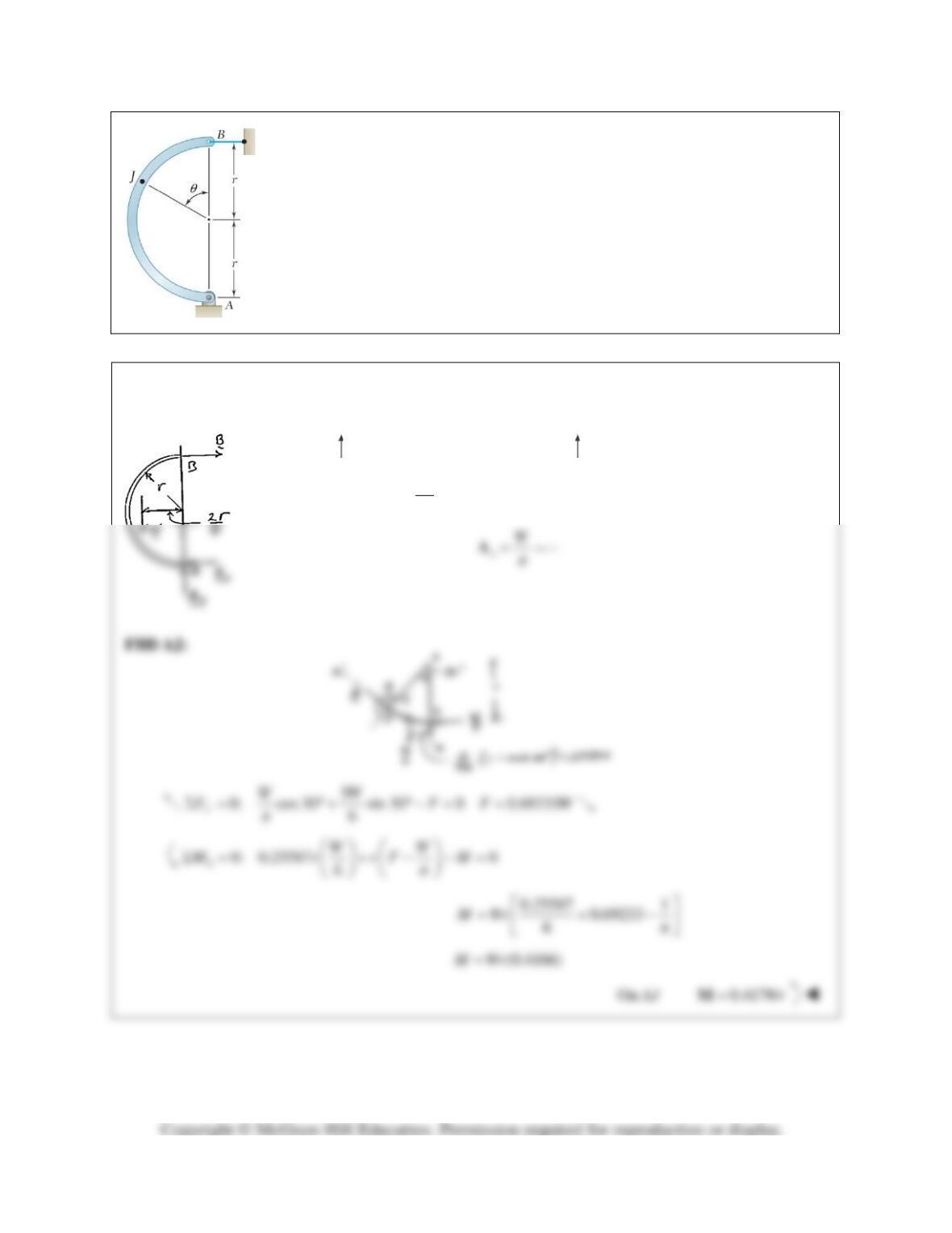
A quarter–circular rod of weight W and uniform cross section is supported as
shown. Determine the bending moment at Point J when
θ
= 30°.
SOLUTION
FBD Rod:
0: 0
xx
FΣ= =A
22
0: 0
B yy
rW
M W rA
ππ
Σ= −= =A
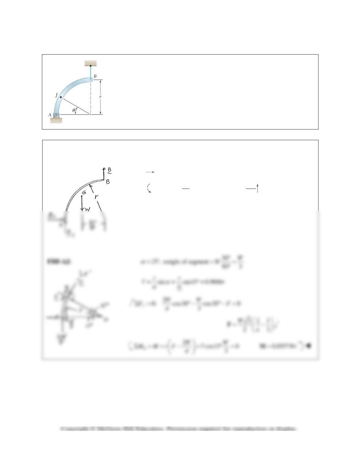
PROBLEM 7.24
PROBLEM 7.23 A quarter–circular rod of weight W and uniform cross section
is supported as shown. Determine the bending moment at Point J when
θ
= 30°.
SOLUTION
FBD Rod:
0: 0
xx
FAΣ= =
22
0: 0
B yy
rW
M W rA A
ππ
Σ= −= =
, sin
2
r
r
θ
αα
α
= =
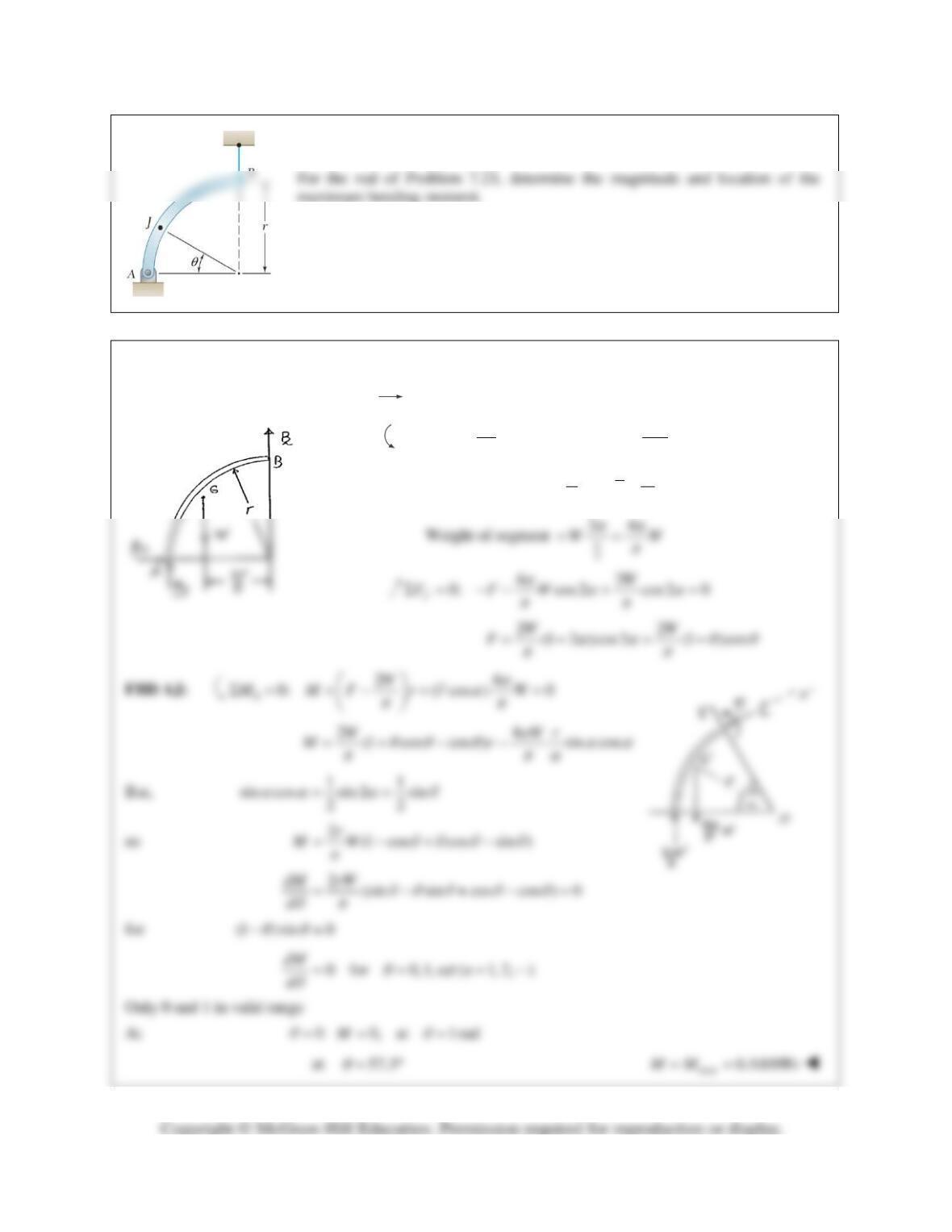
PROBLEM 7.25
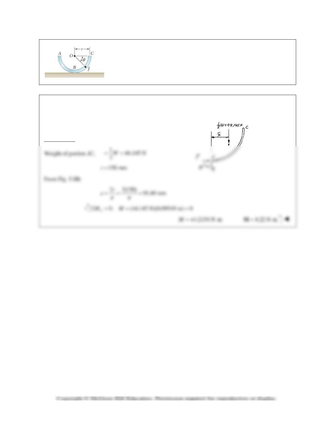
A semicircular rod of weight W and uniform cross section is supported as shown.
Determine the bending moment at Point J when
θ
= 60°.
SOLUTION
FBD Rod:
2
0: 2 0
A
r
M W rB
π
Σ= − =
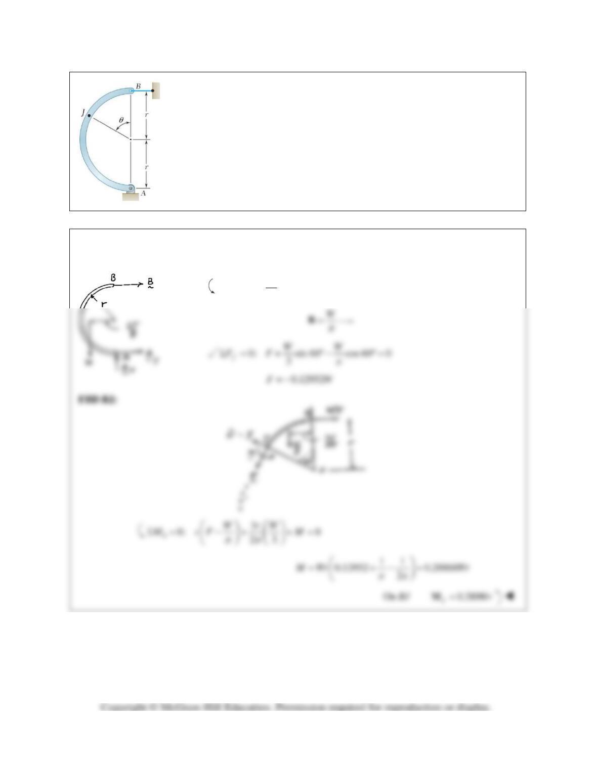
PROBLEM 7.26
A semicircular rod of weight W and uniform cross section is supported as shown.
Determine the bending moment at Point J when
θ
= 150°.
SOLUTION
FBD Rod:
0: 0
yy y
F AW WΣ= −= =A
2
0: 2 0
Bx
r
M W rA
π
Σ= − =
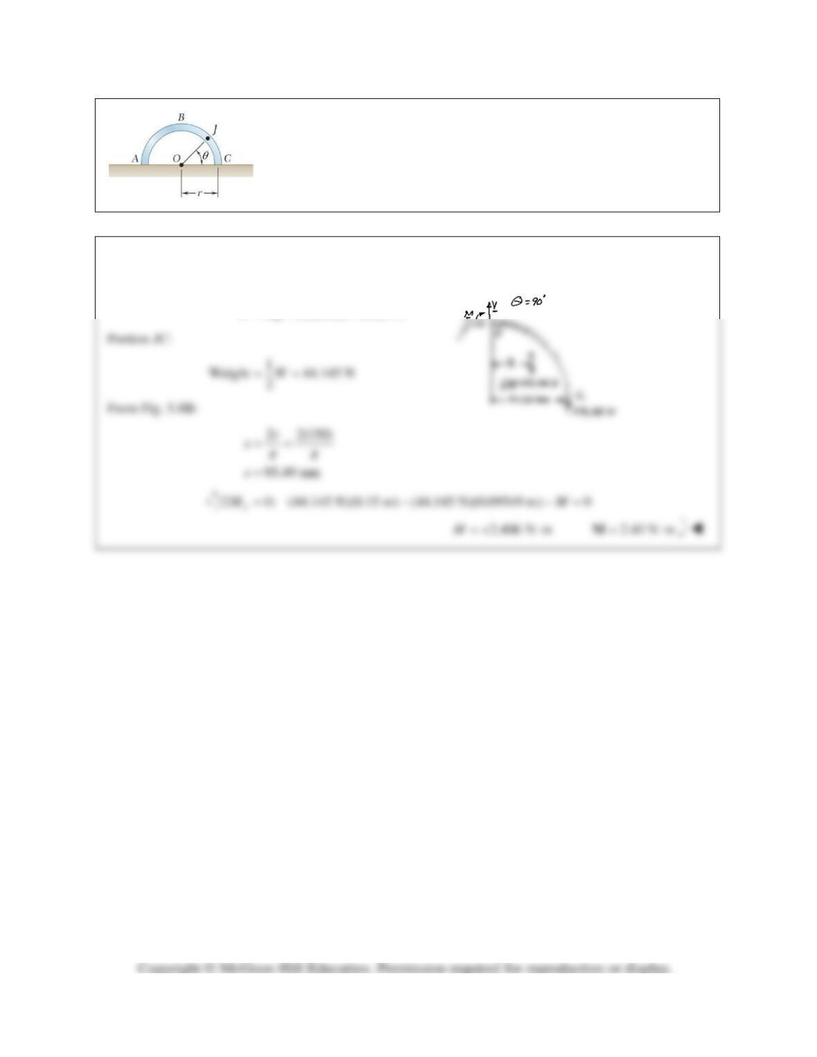
PROBLEM 7.27
A half section of pipe rests on a frictionless horizontal surface as shown. If
the half section of pipe has a mass of 9 kg and a diameter of 300 mm,
determine the bending moment at Point J when
θ
= 90°.
SOLUTION
For half section
9 kgm=
(9)(9.81) 88.29 NW mg= = =
PROBLEM 7.28
A half section of pipe rests on a frictionless horizontal surface as shown. If
the half section of pipe has a mass of 9 kg and a diameter of 300 mm,
determine the bending moment at point J when
θ
= 90°.
SOLUTION
For half section
9 kgm=
2
(9 kg)(9.81 m/s ) 88.29 NW mg= = =
Free body JC
PROBLEM 7.29
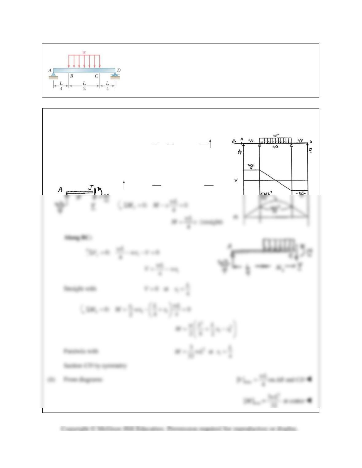
For the beam and loading shown, (a) draw the shear and bending-
moment diagrams, (b) determine the maximum absolute values of the
shear and bending moment.
SOLUTION
FBD beam:
(a) By symmetry:
1()
22
y
L
AD w= =
4
y
wL
= =AD
Along AB:
0: 0
44
y
wL wL
F VVΣ = −= =