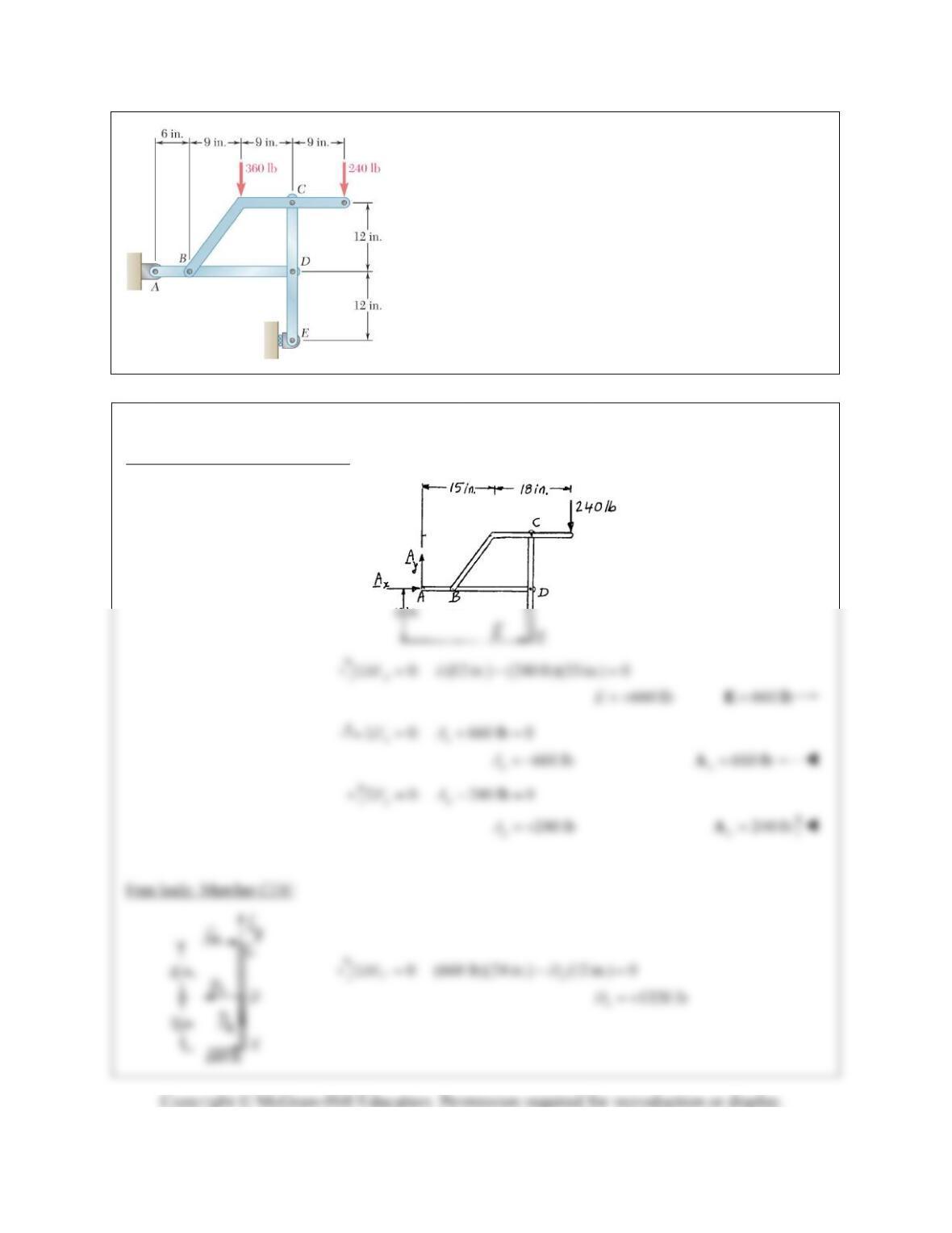
PROBLEM 6.104
Solve Problem 6.103 assuming that the 360-lb load has been
removed.
PROBLEM 6.103
For the frame and loading shown, determine
the components of all forces acting on member ABD.
SOLUTION
Free body diagram of entire frame.
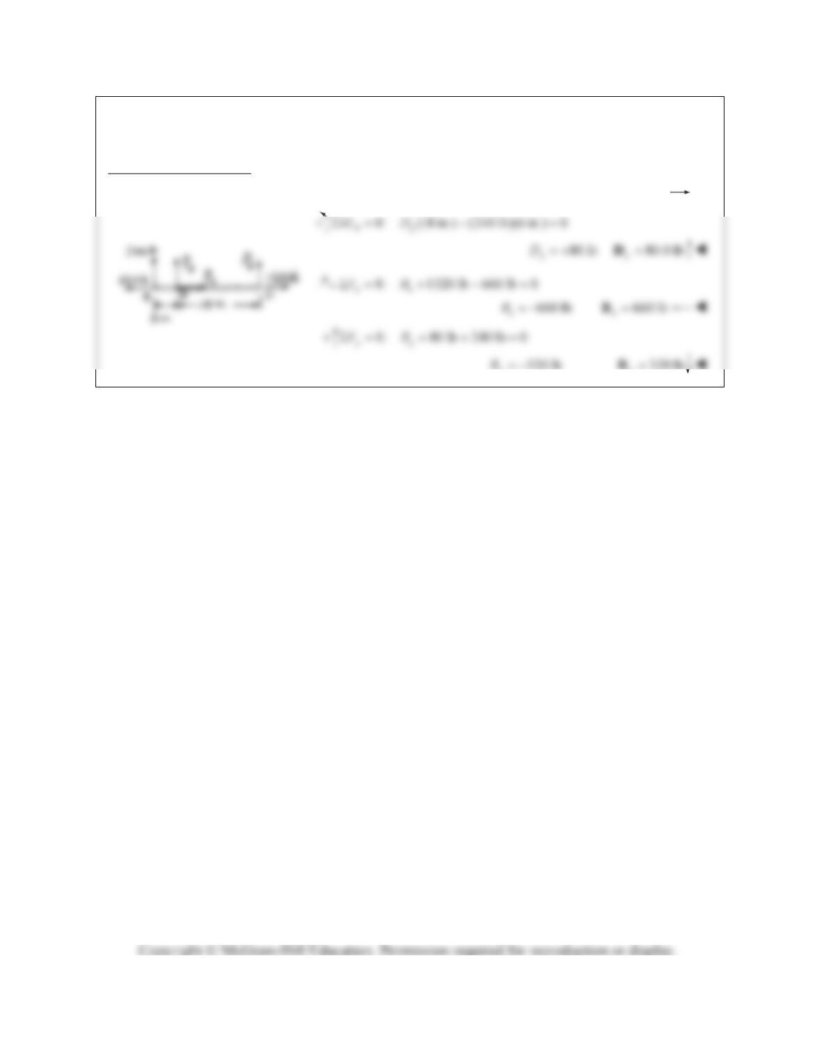
PROBLEM 6.104 (Continued)
Free body: Member ABD:
From above:
1320 lb
x
D
y
y
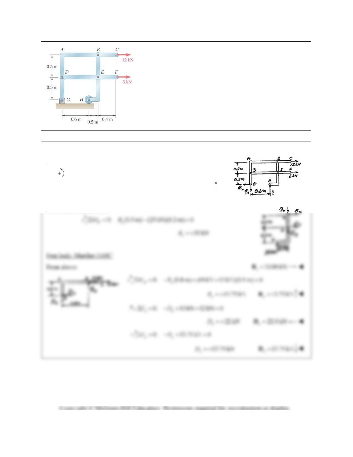
PROBLEM 6.105
For the frame and loading shown, determine the components of
the forces acting on member DABC at B and D.
SOLUTION
Free body: Entire frame:
0 : (0.6 m) (12 kN)(1 m) (6 kN)(0.5 m) 0
G
MH
25 kN 25 kN
H
H
Free body: Member BEH:
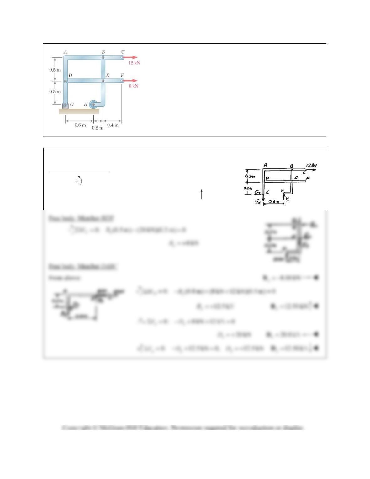
PROBLEM 6.106
Solve Problem 6.105 assuming that the 6-kN load has been
removed.
PROBLEM 6.105
For the frame and loading shown, determine
the components of the forces acting on member DABC at B and D.
SOLUTION
Free body: Entire frame
0 : ( 0 .6 m ) (1 2 k N )(1 m ) 0
G
MH
20 kN 20 kN
H
H
PROBLEM 6.107
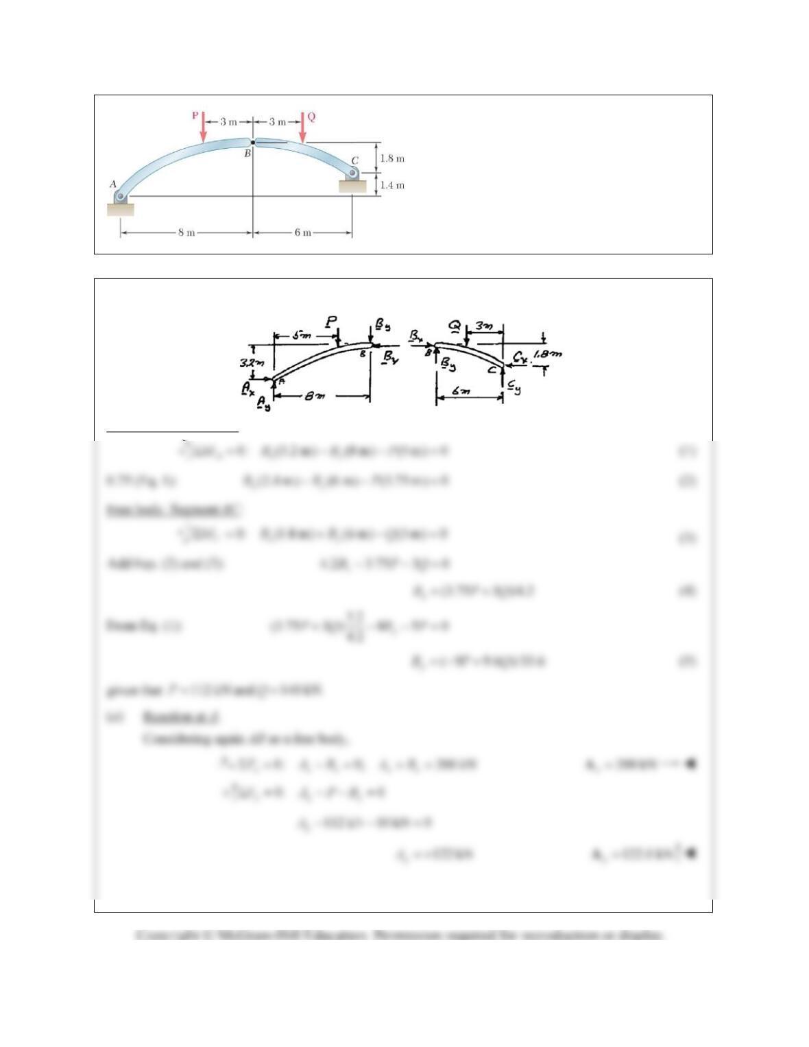
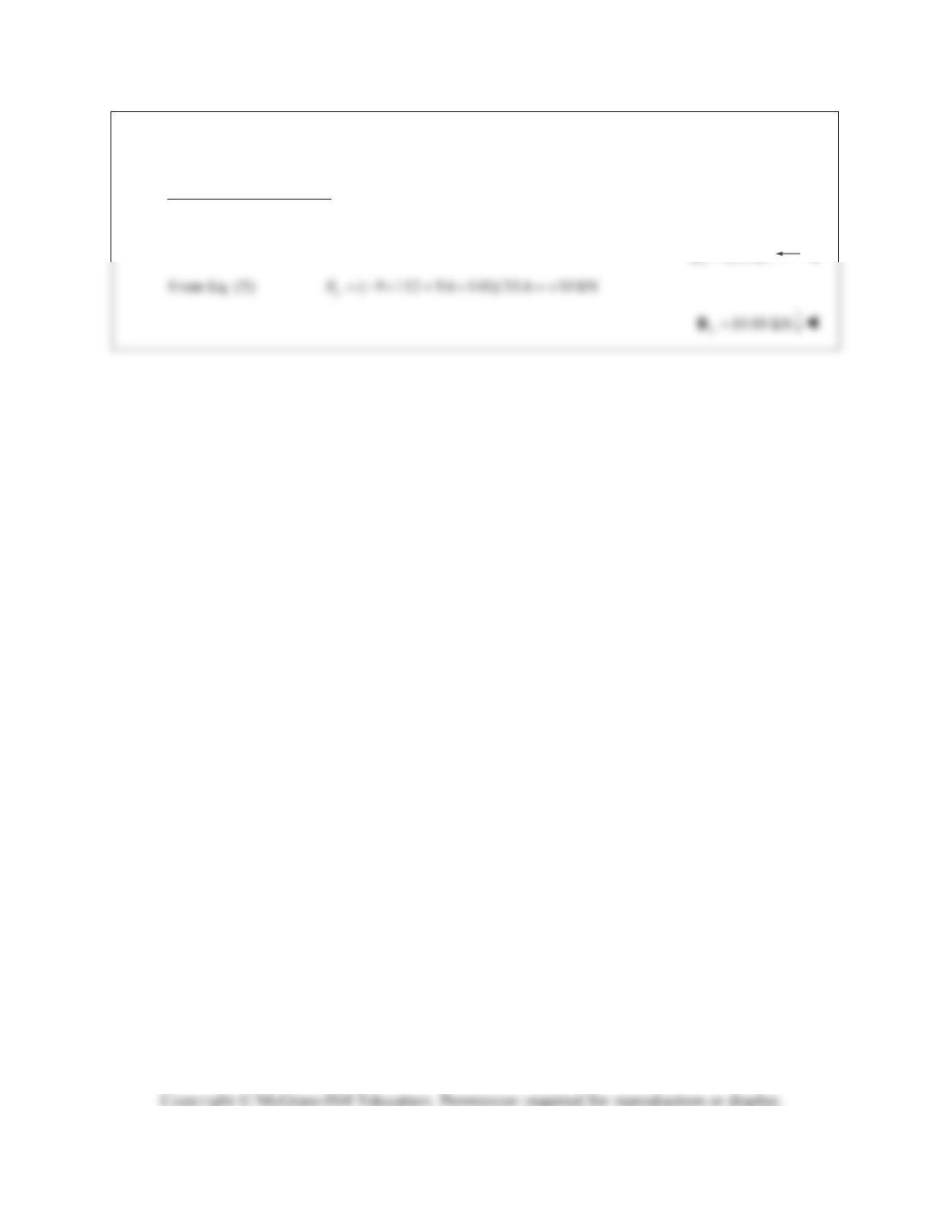
The axis of the three-hinge arch ABC is a
parabola with the vertex at B. Knowing that
P 112 kN and Q 140 kN, determine (a) the
components of the reaction at A, (b) the
components of the force exerted at B on
segment AB.
SOLUTION
Free body: Segment AB:
PROBLEM 6.107 (Continued)
(b) Force exerted at B on AB.
From Eq. (4): (3.75 112 3 140)/4.2 200 kN
x
B
200 kN
PROBLEM 6.108
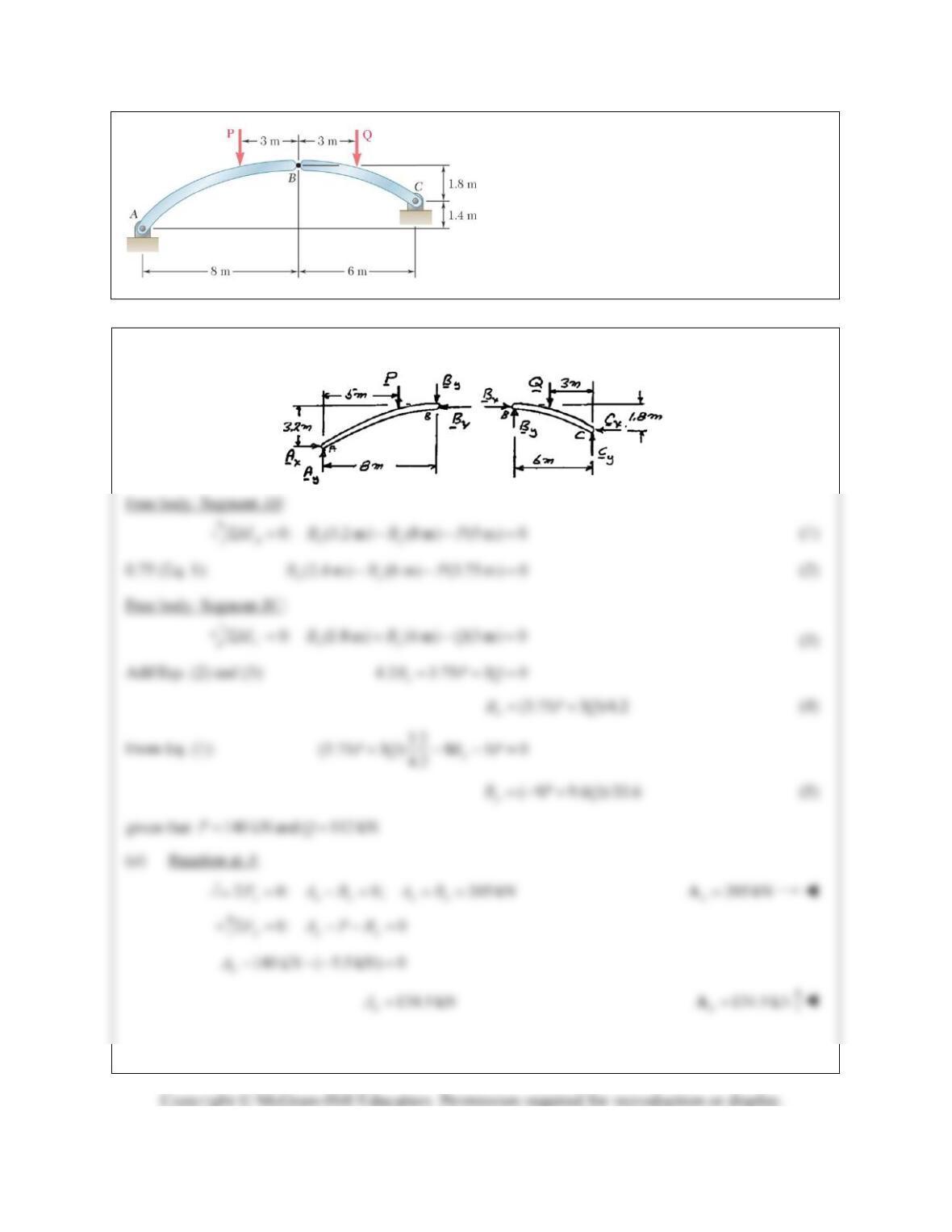
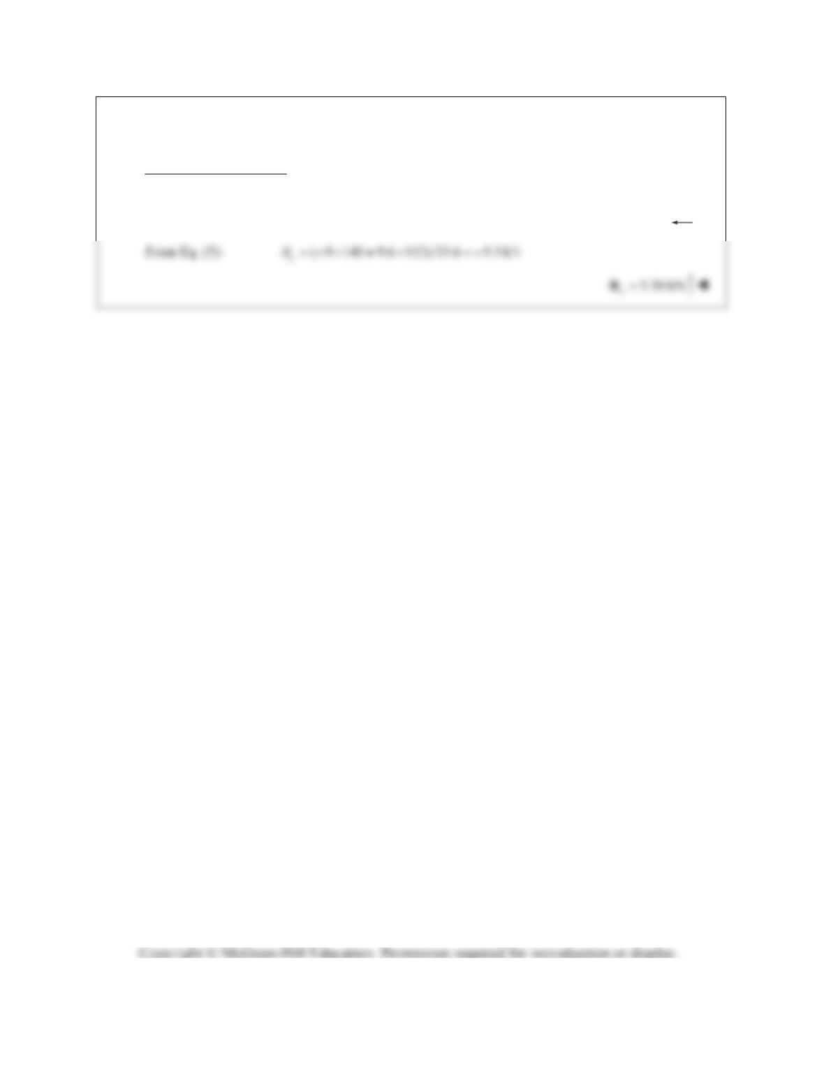
The axis of the three-hinge arch ABC is a
parabola with the vertex at B. Knowing that
P 140 kN and Q 112 kN, determine (a) the
components of the reaction at A, (b) the
components of the force exerted at B on
segment AB.
SOLUTION
PROBLEM 6.108 (Continued)
(b) Force exerted at B on AB.
From Eq. (4):
(3.75 140 3 112)/4.2 205 kN
x
B
205 kN
x
B
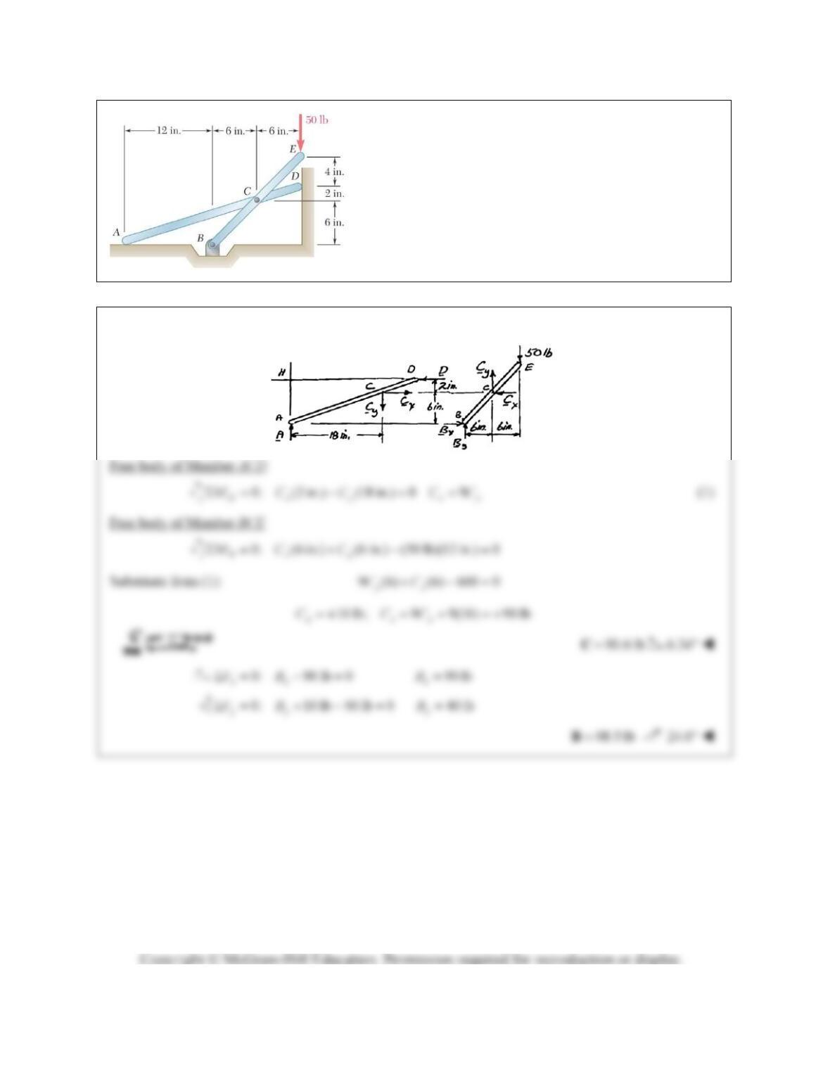
PROBLEM 6.109
Neglecting the effect of friction at the horizontal and vertical
surfaces, determine the forces exerted at B and C on member
BCE.
SOLUTION
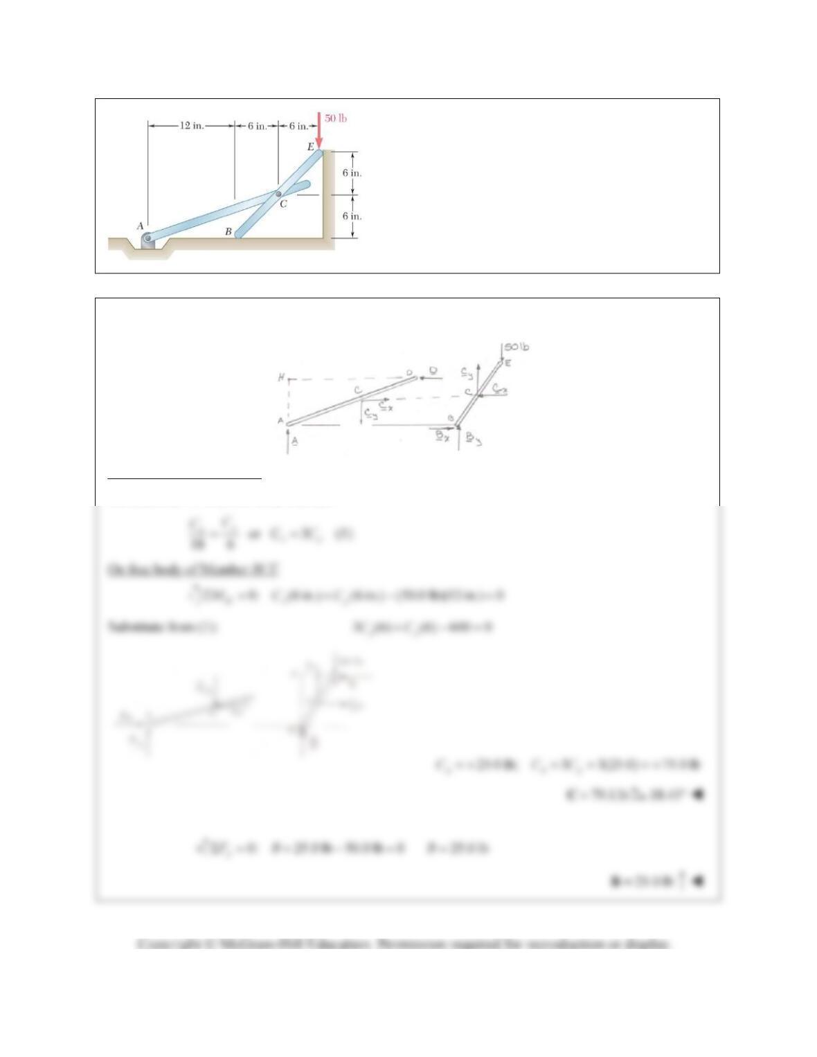
.
PROBLEM 6.110
Neglecting the effect of friction at the horizontal and
vertical surfaces, determine the forces exerted at B and C
on member BCE.
SOLUTION
Free body of Member ACD
We note that AC is a two-force member.
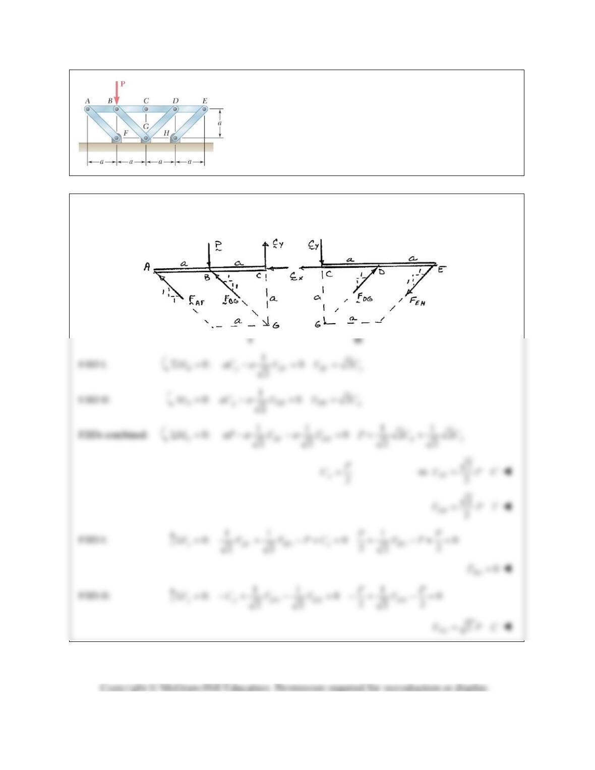
PROBLEM 6.111
Members ABC and CDE are pin-connected at C and supported by
four links. For the loading shown, determine the force in each
link.
SOLUTION
Member FBDs:
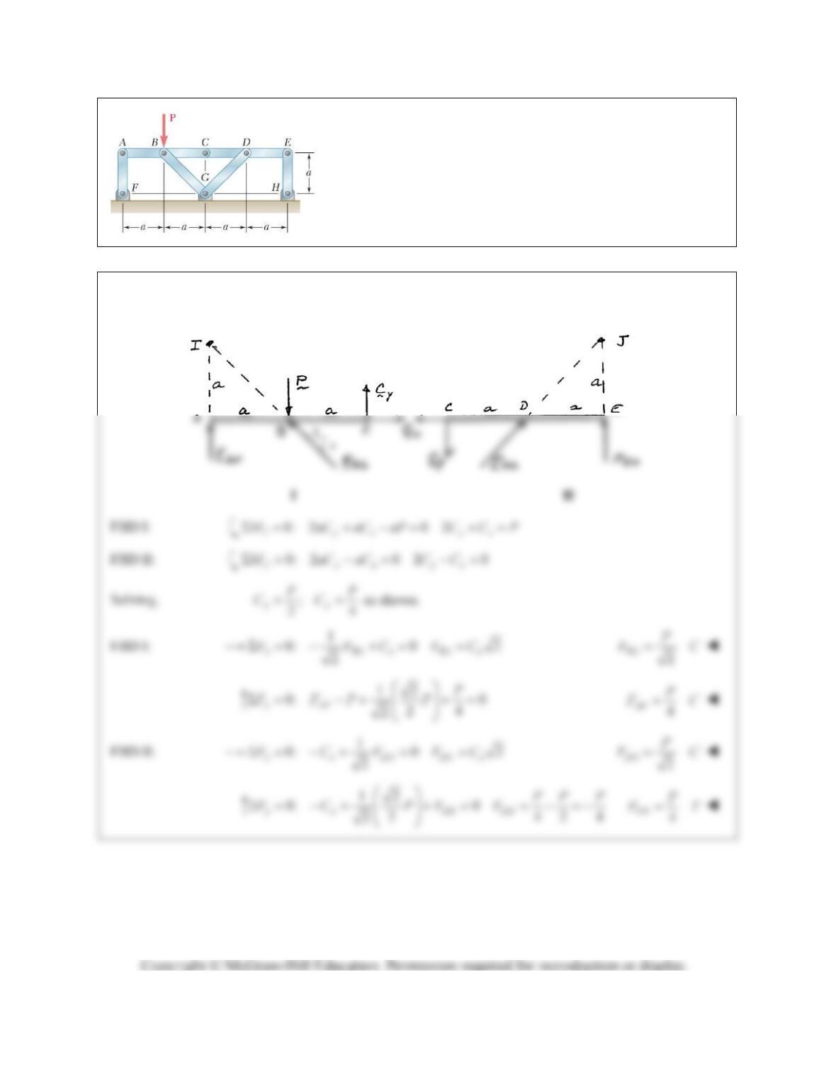
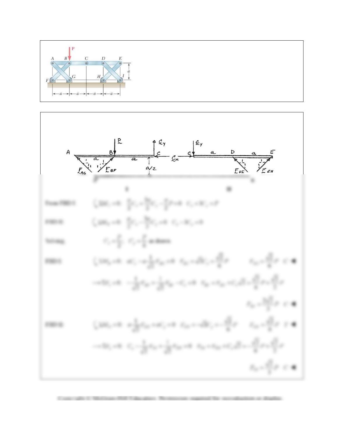
PROBLEM 6.112
Members ABC and CDE are pin-connected at C and supported by
four links. For the loading shown, determine the force in each
link.
SOLUTION
Member FBDs:
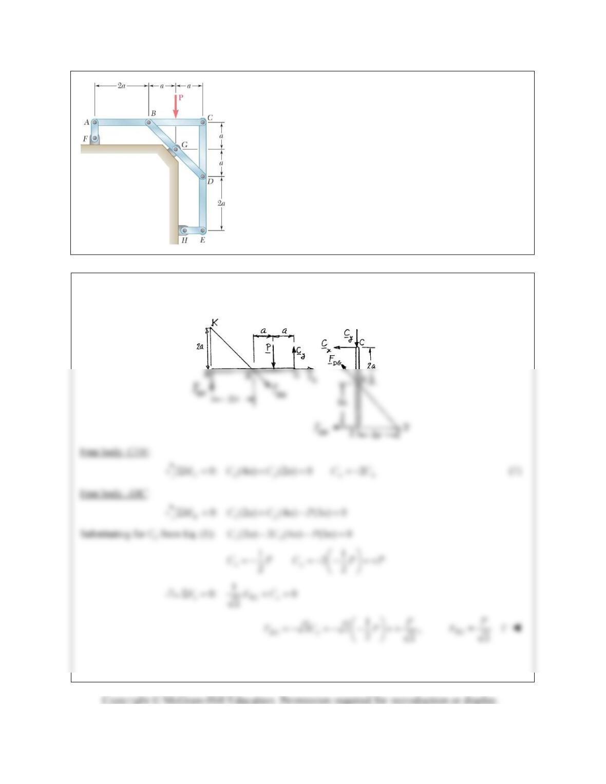
PROBLEM 6.113
Members ABC and CDE are pin-connected at C and supported by
four links. For the loading shown, determine the force in each
link.
SOLUTION
Member FBDs:
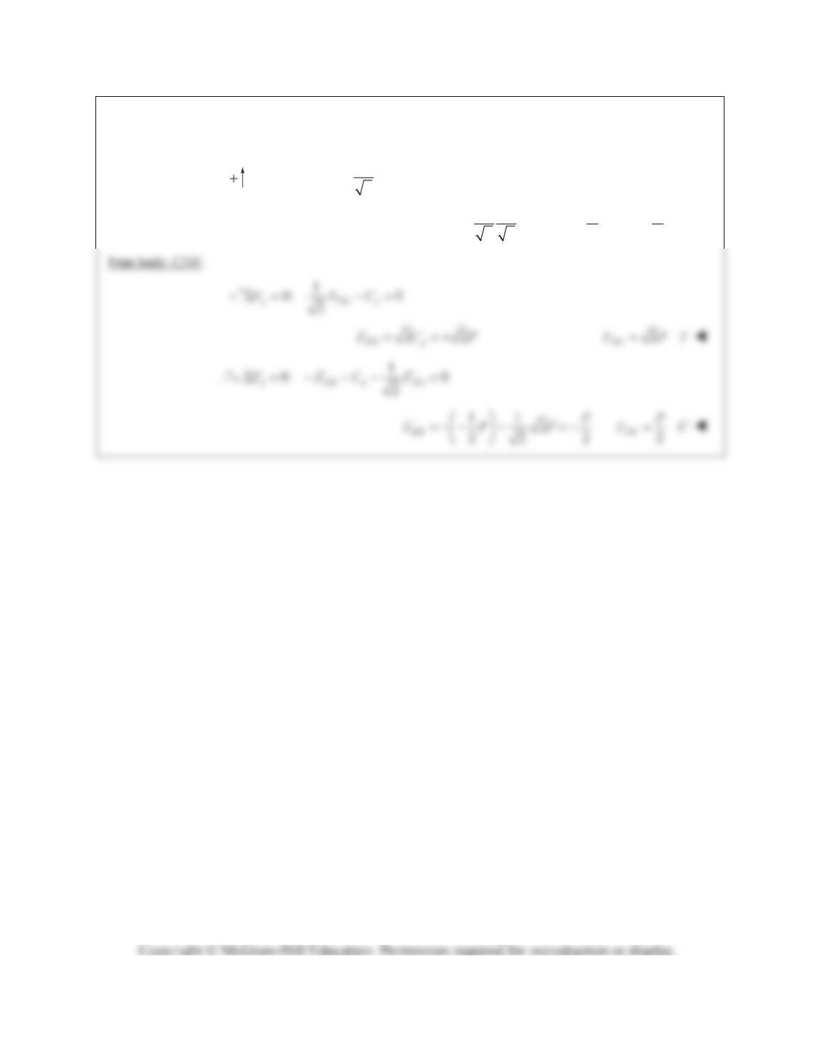
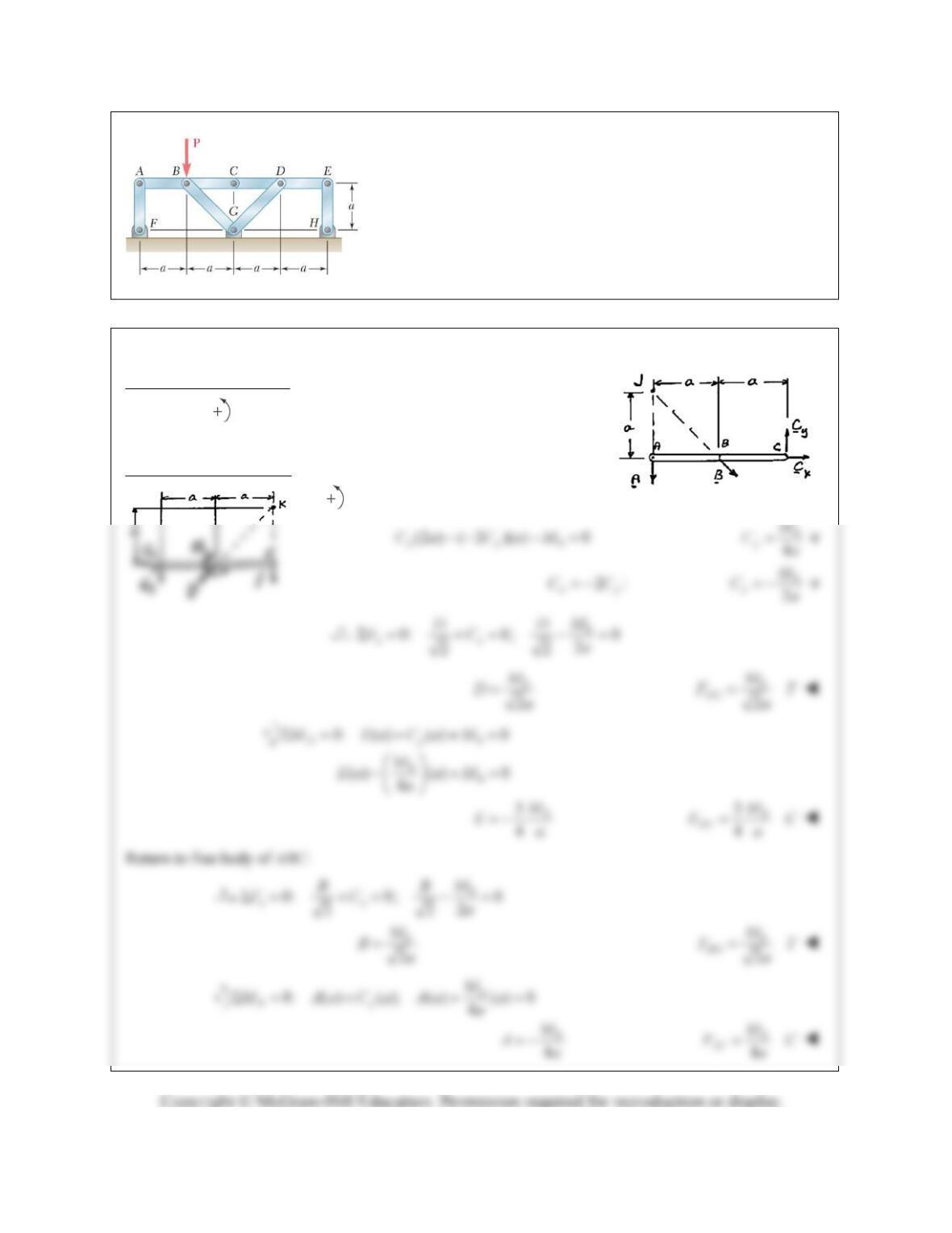
PROBLEM 6.114
Members ABC and CDE are pin-connected at C and supported by
the four links AF, BG, DG, and EH. For the loading shown,
determine the force in each link.
SOLUTION
We consider members ABC and CDE:
PROBLEM 6.114 (Continued)
1
0: 0
2
yAFBGy
FFFPC
1
2
22
AF
PP
FPP
2
AF
P
FC
PROBLEM 6.115
Solve Problem 6.112 assuming that the force
P
is replaced by a
clockwise couple of moment
M
0 applied to member CDE at D.
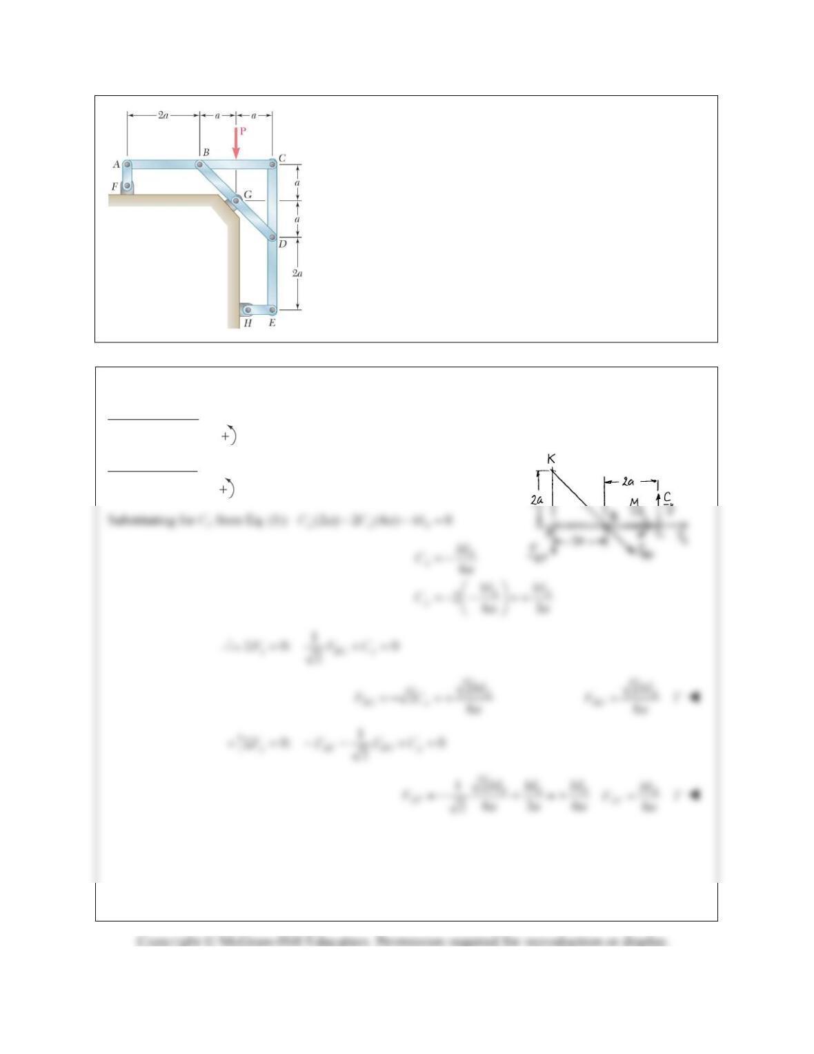
PROBLEM 6.112
Members ABC and CDE are pin-connected at
C and supported by four links. For the loading shown, determine
the force in each link.
SOLUTION
Free body: Member ABC:
0: (2 ) ( ) 0
Jyx
MCaCa
2
xy
CC
Free body: Member CDE:
0
0: (2 ) ( ) 0
Kyx
MCaCaM
PROBLEM 6.116
Solve Problem 6.114 assuming that the force
P
is replaced by a
clockwise couple of moment
M
0 applied at the same point.
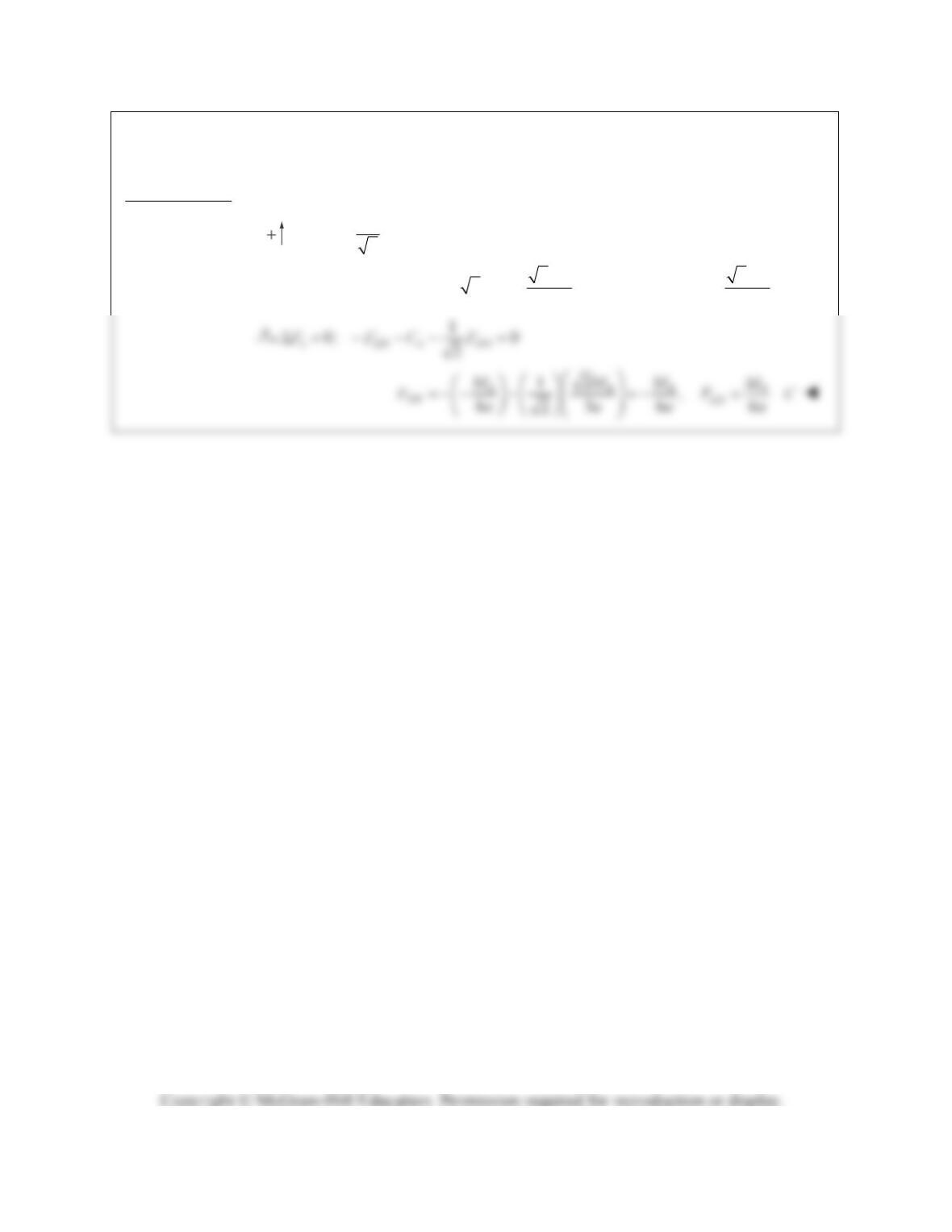
PROBLEM 6.114
Members ABC and CDE are pin-connected at C
and supported by the four links AF, BG, DG, and EH. For the
loading shown, determine the force in each link.
SOLUTION
Free body: CDE: (same as for Problem 6.114)
0: (4 ) (2 ) 0
Jxy
MCaCa
2
yx
CC
(1)
Free body: ABC:
0
0: (2 ) (4 ) 0
Kxy
MCaCaM
PROBLEM 6.116 (Continued)
Free body: CDE: (Use F.B. diagram of Problem 6.114.)
1
0: 0
2
yDGy
FFC
0
2
23
DG y
M
FC a
0
2
3
DG
M
FT
a
PROBLEM 6.117
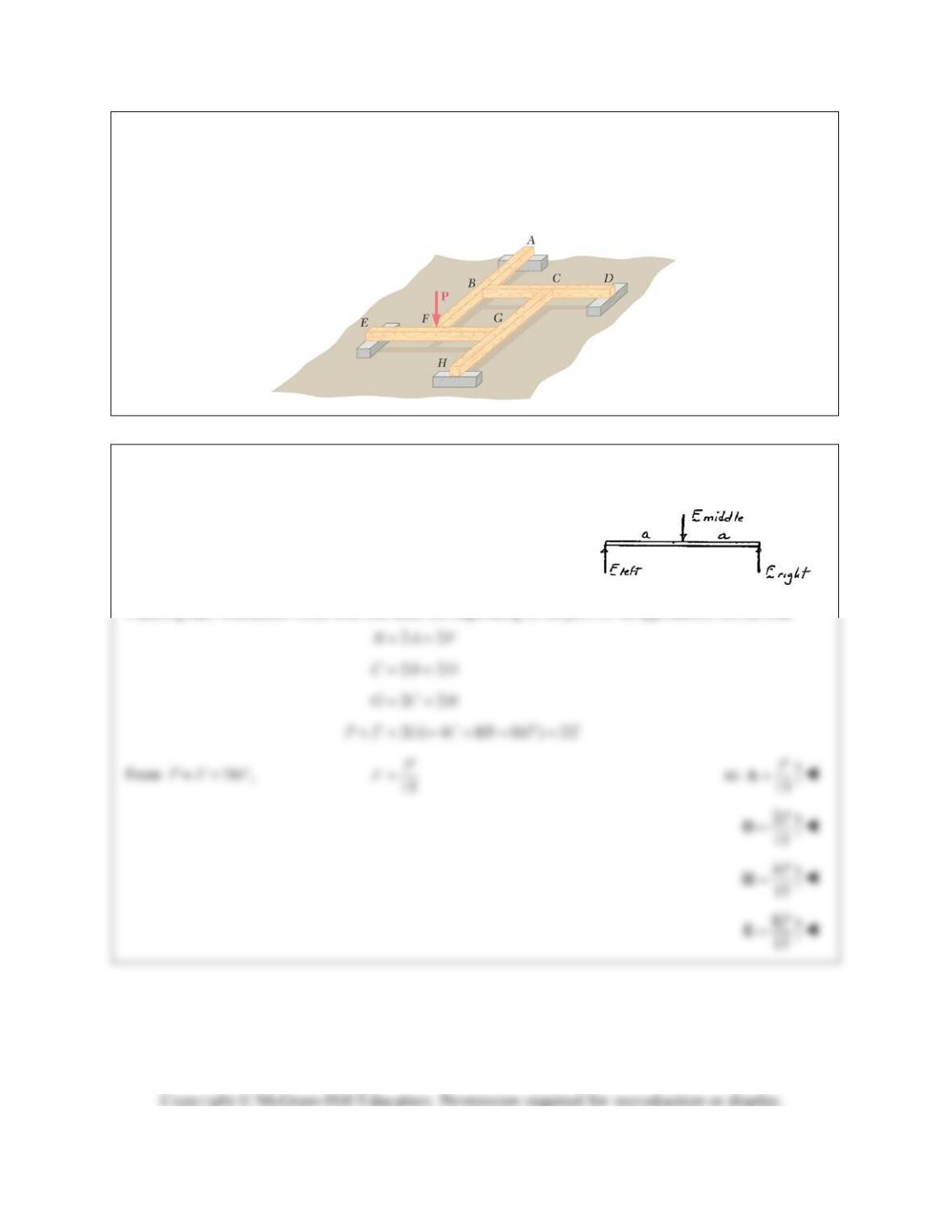
Four beams, each of length 2a, are nailed together at their midpoints to form the support system shown.
Assuming that only vertical forces are exerted at the connections, determine the vertical reactions at A, D,
E, and H.
SOLUTION
Note that, if we assume P is applied to EG, each individual member FBD looks like
so
left right middle
22FFF
Labeling each interaction force with the letter corresponding to the joint of its application, we see that
PROBLEM 6.118
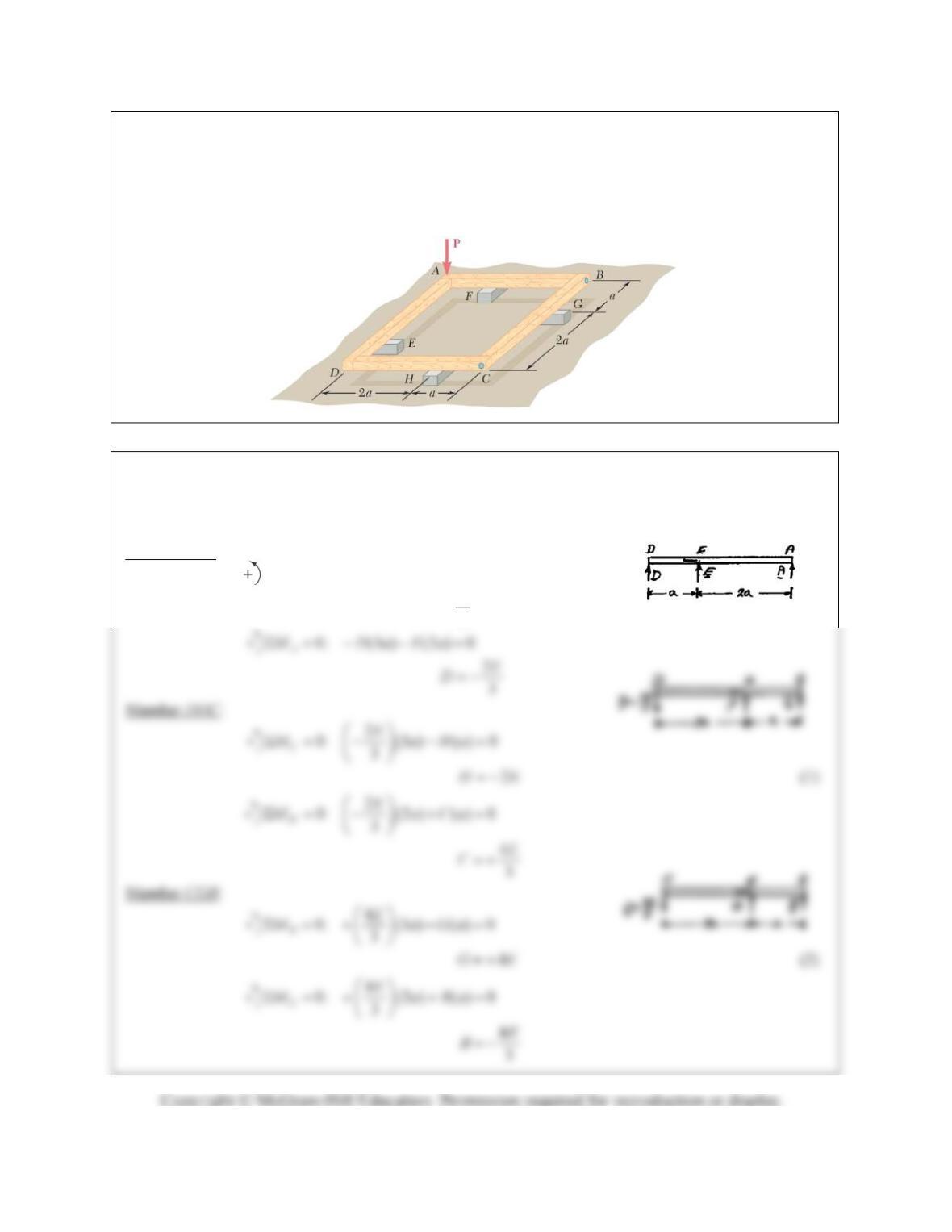
Four beams, each of length 3a, are held together by single nails at A, B, C, and D. Each beam is attached
to a support located at a distance a from an end of the beam as shown. Assuming that only vertical forces
are exerted at the connections, determine the vertical reactions at E, F, G, and H.
SOLUTION
We shall draw the free body of each member. Force
P
will be applied to member AFB. Starting with
member AED, we shall express all forces in terms of reaction E.
Member AED:
0: (3 ) ( ) 0
D
MAaEa
3
E
A