Archives

978-0073398242 Appendix B Solution Manual Part 1
APPENDIX B PROBLEM B.1 A thin plate of mass m is cut in the shape of an equilateral triangle of side a. Determine the mass moment of inertia of the plate with respect to (a) the centroidal axes AA and […]
978-0073398242 Appendix B Solution Manual Part 10
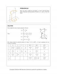
PROBLEM B.50 Brass wire with a weight per unit length w is used to form the figure shown. Determine the mass products of inertia I xy , I yz , and I zx of the wire figure. SOLUTION First compute […]
978-0073398242 Appendix B Solution Manual Part 11
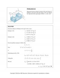
PROBLEM B.56 Determine the mass moment of inertia of the steel fixture of Problems 9.145 and 9.149 with respect to the axis through the origin that forms equal angles with the x, y, and z axes. SOLUTION From the solutions […]
978-0073398242 Appendix B Solution Manual Part 12
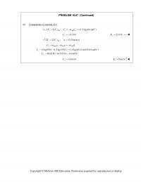
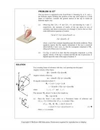
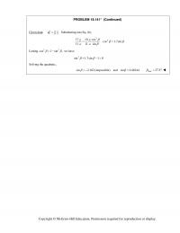
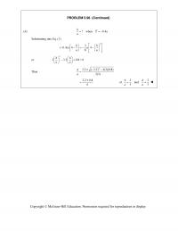
PROBLEM B.61 (Continued) From the solution to Problem 9.147, we have 36.2542 10 lb ft s y I 32 32 32 39.1721 10 lb ft s 30.4184 10 lb ft s I x z I […]
978-0073398242 Appendix B Solution Manual Part 13
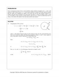
PROBLEM B.68 Given a homogeneous body of mass m and of arbitrary shape and three rectangular axes x , y , and z with origin at O , prove that the sum Ix + Iy + Iz of the mass […]
978-0073398242 Appendix B Solution Manual Part 14
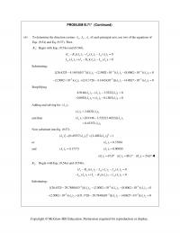
PROBLEM B.71* (Continued) (b) To determine the direction cosines , , x yz of each principal axis, use two of the equations of Eqs. (9.54) and Eq. (9.57). Then 1:K Begin with Eqs. (9.54a) and (9.54b). 11 1 […]
978-0073398242 Appendix B Solution Manual Part 15
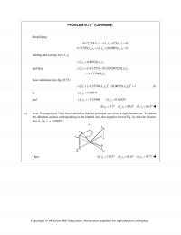
PROBLEM B.73* (Continued) Simplifying 33 3 33 3 xy z 0.12533( ) ( ) 0.5( ) 0 0.11705( ) ( ) 0.62695( ) 0 xy z Adding and solving for 3 () z […]
978-0073398242 Appendix B Solution Manual Part 2
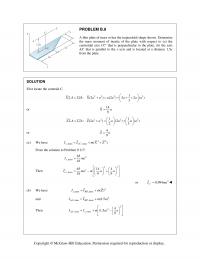
PROBLEM B.8 A thin plate of mass m has the trapezoidal shape shown. Determine the mass moment of inertia of the plate with respect to (a) the centroidal axis CC that is perpendicular to the plate, (b) the axis AA […]
978-0073398242 Appendix B Solution Manual Part 3
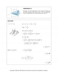
PROBLEM B.14 Determine by direct integration the mass moment of inertia and the radius of gyration with respect to the x axis of the paraboloid shown, assuming that it has a uniform density and a mass m. SOLUTION 222 :ryzkx […]
978-0073398242 Appendix B Solution Manual Part 4
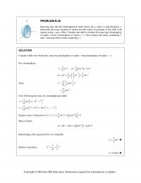
PROBLEM B.20 Knowing that the thin hemispherical shell shown has a mass m and thickness t, determine the mass moment of inertia and the radius of gyration of the shell with respect to the x axis. (Hint: Consider the shell […]
978-0073398242 Appendix B Solution Manual Part 5
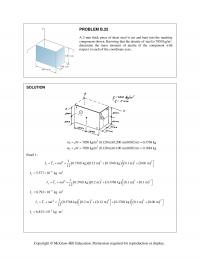
PROBLEM B.25 A 2-mm thick piece of sheet steel is cut and bent into the machine component shown. Knowing that the density of steel is 7850 kg/m3, determine the mass moment of inertia of the component with respect to each […]
978-0073398242 Appendix B Solution Manual Part 6
PROBLEM B.29 (Continued) 123 62 2 22 22 2 62 2 1(3325.97 10 lb s /ft)[(2.25) (3.5) ] in 12 2.25 3.5 1 ft () () () (3325.97 10 […]
978-0073398242 Appendix B Solution Manual Part 7
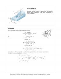
PROBLEM B.34 Determine the mass moment of inertia of the steel machine element shown with respect to the yaxis. (The density of steel is 3 490 lb/ft .) SOLUTION First compute the mass of each component. We have 2 490 […]
978-0073398242 Appendix B Solution Manual Part 8
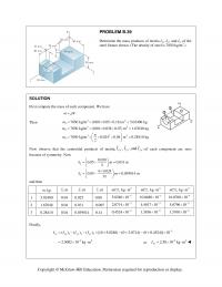
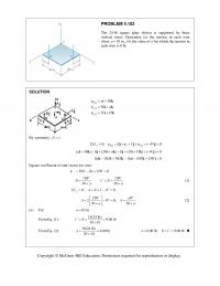
PROBLEM B.39 Determine the mass products of inertia I xy , I yz , and I zx of the steel fixture shown. (The density of steel is 7850 kg/m 3 .) SOLUTION First compute the mass of each component. We […]
978-0073398242 Appendix B Solution Manual Part 9
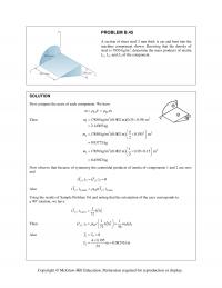
PROBLEM B.45 A section of sheet steel 2 mm thick is cut and bent into the machine component shown. Knowing that the density of steel is 7850 kg/m 3 , determine the mass products of inertia I xy , I […]
978-0073398242 Chapter 10 Solution Manual Part 1
CHAPTER 10 PROBLEM 10.1 Determine the vertical force P that must be applied at C to maintain the equilibrium of the linkage. SOLUTION Assume A y 2 CA yy DA yy 11 22 EDA yyy […]
978-0073398242 Chapter 10 Solution Manual Part 10
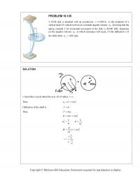
PROBLEM 10.80 A slender rod AB, of weight W, is attached to two blocks A and B that can move freely in the guides shown. Knowing that the spring is unstretched when AB is horizontal, determine three values of […]
978-0073398242 Chapter 10 Solution Manual Part 11
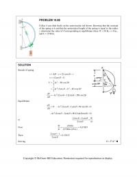
PROBLEM 10.88 Collar A can slide freely on the semicircular rod shown. Knowing that the constant of the spring is k and that the unstretched length of the spring is equal to the radius r, determine the value of […]
978-0073398242 Chapter 10 Solution Manual Part 12
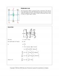
PROBLEM 10.95 The horizontal bar BEH is connected to three vertical bars. The collar at E can slide freely on bar DF. Determine the range of values of Q for which the equilibrium of the system is stable in the […]
978-0073398242 Chapter 10 Solution Manual Part 13
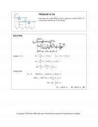
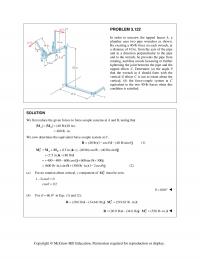
PROBLEM 10.102 Determine the couple M that must be applied to member DEFG to maintain the equilibrium of the linkage. SOLUTION Assume A y : 12 1.5 8 CAA yyy , 1.5 EC A yy y […]
978-0073398242 Chapter 10 Solution Manual Part 2
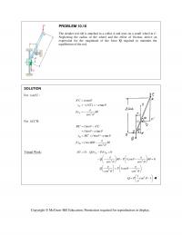
PROBLEM 10.10 The slender rod AB is attached to a collar A and rests on a small wheel at C. Neglecting the radius of the wheel and the effect of friction, derive an expression for the magnitude of the force […]
978-0073398242 Chapter 10 Solution Manual Part 3
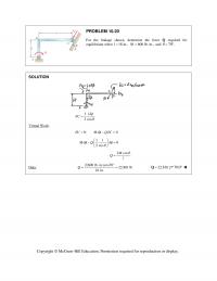
PROBLEM 10.20 For the linkage shown, determine the force Q required for equilibrium when 18 in.,l 600 lb in.,M and 70 . SOLUTION 1 2cos l C Virtual Work: 0:U 0MQC […]
978-0073398242 Chapter 10 Solution Manual Part 4
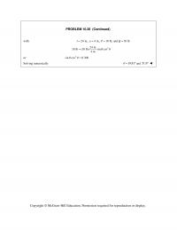
PROBLEM 10.26 (Continued) with 24 in., 4 in., 10 lb, and 18 lblaP Q 2 24 in. 18 lb (10 lb) sin cos 4 in. or 2 sin cos 0.300 Solving numerically […]
978-0073398242 Chapter 10 Solution Manual Part 5
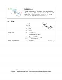
PROBLEM 10.36 A load W of magnitude 72 lb is applied to the mechanism at C. Neglecting the weight of the mechanism, determine the value of corresponding to equilibrium. The constant of the spring is 20 lb/in.,k and the […]
978-0073398242 Chapter 10 Solution Manual Part 6
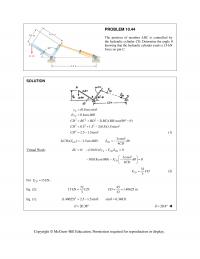
PROBLEM 10.44 The position of member ABC is controlled by the hydraulic cylinder CD. Determine the angle knowing that the hydraulic cylinder exerts a 15-kN force on pin C. SOLUTION 222 222 2 (0.8 m)sin 0.8cos 2( )( )cos(90 […]
978-0073398242 Chapter 10 Solution Manual Part 7
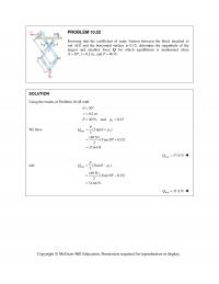
PROBLEM 10.52 Knowing that the coefficient of static friction between the block attached to rod ACE and the horizontal surface is 0.15, determine the magnitude of the largest and smallest force Q for which equilibrium is maintained when 30 , […]
978-0073398242 Chapter 10 Solution Manual Part 8
PROBLEM 10.61 Using the method of Section 10.8, solve Problem 10.31. PROBLEM 10.31 Solve Problem 10.30 assuming that force P is moved to C and acts vertically downward. SOLUTION Spring: 2(2 sin ) 4 sinAE x l l […]
978-0073398242 Chapter 10 Solution Manual Part 9
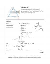
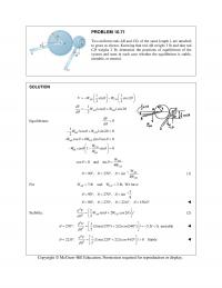
PROBLEM 10.71 Two uniform rods AB and CD, of the same length l, are attached to gears as shown. Knowing that rod AB weighs 3 lb and that rod CD weighs 2 lb, determine the positions of equilibrium of the […]
978-0073398242 Chapter 11 Solution Manual Part 1
CHAPTER 11 PROBLEM 11.1 A snowboarder starts from rest at the top of a double black diamond hill. As he rides down the slope, GPS coordinates are used to determine his displacement as a function of time: x= 0.5t3 + […]
978-0073398242 Chapter 11 Solution Manual Part 10
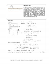
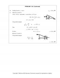
PROBLEM 11.71 In a 400-m race, runner A reaches her maximum velocity A v in 4 s with constant acceleration and maintains that velocity until she reaches the half-way point with a split time of 25 s. Runner B reaches […]
978-0073398242 Chapter 11 Solution Manual Part 11
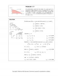
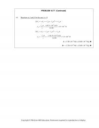
PROBLEM 11.77 An accelerometer record for the motion of a given part of a mechanism is approximated by an arc of a parabola for 0.2 s and a straight line for the next 0.2 s as shown in the figure. […]
978-0073398242 Chapter 11 Solution Manual Part 12
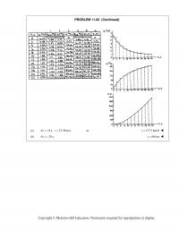
PROBLEM 11.82 (Continued) (a) At 8 s, 32.58 m/stv or 117.3 km/hv (b) At 20 st 660 mx Copyright © McGraw-Hill Education. Permission required for reproduction or display. PROBLEM 11.83 A training airplane has a velocity of 126 […]
978-0073398242 Chapter 11 Solution Manual Part 13
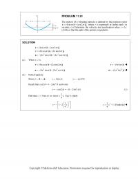
PROBLEM 11.91 The motion of a vibrating particle is defined by the position vector (4sin ) (cos2 ) ,tt rij where r is expressed in inches and t in seconds. (a) Determine the velocity and acceleration when […]
978-0073398242 Chapter 11 Solution Manual Part 14
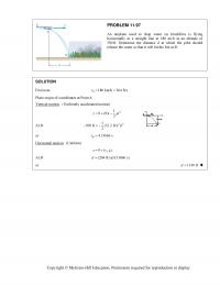
PROBLEM 11.97 An airplane used to drop water on brushfires is flying horizontally in a straight line at 180 mi/h at an altitude of 300 ft. Determine the distance d at which the pilot should release the water so that […]
978-0073398242 Chapter 11 Solution Manual Part 15
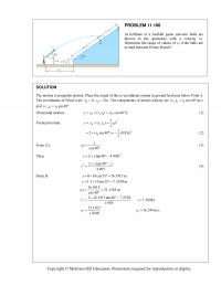
PROBLEM 11.106 At halftime of a football game souvenir balls are thrown to the spectators with a velocity v0. Determine the range of values of v0 if the balls are to land between Points B and C. SOLUTION The motion […]
978-0073398242 Chapter 11 Solution Manual Part 16
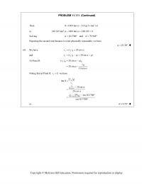
PROBLEM 11.111 (Continued) Then 2 8 1400 tan 24.5 (1 tan )g or 2 240.345 tan 1400 tan 248.345 0 Solving 10.3786 and 79.949 Rejecting the second root because it […]
978-0073398242 Chapter 11 Solution Manual Part 17
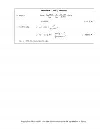
PROBLEM 11.116* (Continued) (b) Angle Check the edge. Since the stream clears the edge. . max max tan 1.875 21.466 xx 61.93 61.9 2 02 0 tan 2cos gx yy x […]
978-0073398242 Chapter 11 Solution Manual Part 18
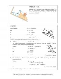
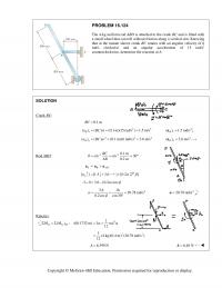
PROBLEM 11.124 Knowing that at the instant shown block A has a velocity of 8 in./s and an acceleration of 6 in./s 2 both directed down the incline, determine (a) the velocity of block B, (b) the acceleration of block […]
978-0073398242 Chapter 11 Solution Manual Part 19
PROBLEM 11.131 (Continued) Therefore 520 sin (40 ) sin (130 ) or sin 130 cos cos 130 sin 4(sin 40 cos cos 40 sin ) or sin 130 4 […]
978-0073398242 Chapter 11 Solution Manual Part 2
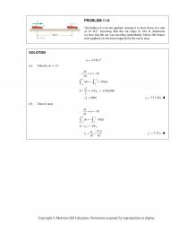
PROBLEM 11.9 The brakes of a car are applied, causing it to slow down at a rate of 10 ft/s2. Knowing that the car stops in 100 ft, determine (a) how fast the car was traveling immediately before the brakes […]
978-0073398242 Chapter 11 Solution Manual Part 20
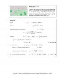
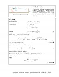
PROBLEM 11.140 A motorist starts from rest at Point A on a circular entrance ramp when t 0, increases the speed of her automobile at a constant rate and enters the highway at Point B. Knowing that her speed […]
978-0073398242 Chapter 11 Solution Manual Part 21
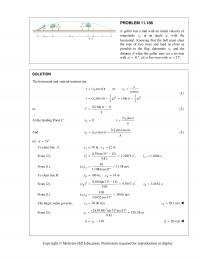
PROBLEM 11.149 A child throws a ball from point A with an initial velocity v0 at an angle of 3 with the horizontal. Knowing that the ball hits a wall at point B, determine (a) the magnitude of the initial […]
978-0073398242 Chapter 11 Solution Manual Part 22
PROBLEM 11.158 A satellite will travel indefinitely in a circular orbit around the earth if the normal component of its acceleration is equal to 2 / g Rr, where 2 9.81 m/sg, R = radius of the earth = […]
978-0073398242 Chapter 11 Solution Manual Part 23
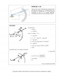
PROBLEM 11.166 The pin at B is free to slide along the circular slot DE and along the rotating rod OC. Assuming that the rod OC rotates at a constant rate , (a) show that the acceleration of pin […]
978-0073398242 Chapter 11 Solution Manual Part 24
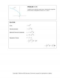
PROBLEM 11.173 A particle moves along the spiral shown. Determine the magnitude of the velocity of the particle in terms of b, , and . SOLUTION Given: 2 1 2 rbe Take time derivative 2 […]
978-0073398242 Chapter 11 Solution Manual Part 25
PROBLEM 11.181* Determine the direction of the binormal of the path described by the particle of Problem 11.96 when (a) 0,t (b) /2 s.t SOLUTION Given: 2 (cos) 1 (sin) A tt At Bttri jk ft, […]
978-0073398242 Chapter 11 Solution Manual Part 26
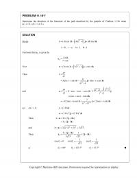
PROBLEM 11.188 A golfer hits a ball with an initial velocity of magnitude 0 v at an angle with the horizontal. Knowing that the ball must clear the tops of two trees and land as close as possible to […]
978-0073398242 Chapter 11 Solution Manual Part 27
PROBLEM 11.193 (Continued) Multiply Eq. (1) by sin 30° and Eq. (2) by cos 30° and subtract 2 2 sin 30 ( 10)cos30 0 (109.95 )sin 30 (12.654 16.1 10)cos30 0 13.943 44.016 8.6603 0 xy ttt tt […]
978-0073398242 Chapter 11 Solution Manual Part 3
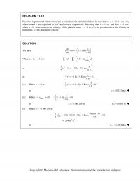
PROBLEM 11.19 Based on experimental observations, the acceleration of a particle is defined by the relation (0.1a sin x/b), where a and x are expressed in m/s2 and meters, respectively. Knowing that 0.8 mb and that 1 m/sv when […]
978-0073398242 Chapter 11 Solution Manual Part 4
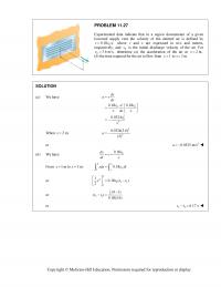
PROBLEM 11.27 Experimental data indicate that in a region downstream of a given louvered supply vent the velocity of the emitted air is defined by 0 0.18 / ,vvx where v and x are expressed in m/s and meters, respectively, […]
978-0073398242 Chapter 11 Solution Manual Part 5
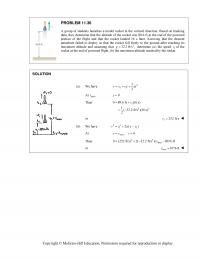
PROBLEM 11.36 A group of students launches a model rocket in the vertical direction. Based on tracking data, they determine that the altitude of the rocket was 89.6 ft at the end of the powered portion of the flight and […]
978-0073398242 Chapter 11 Solution Manual Part 6
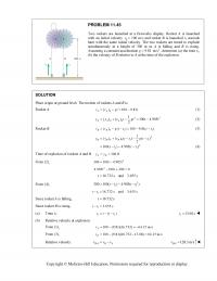
PROBLEM 11.45 Two rockets are launched at a fireworks display. Rocket A is launched with an initial velocity 0 v 100 m/s and rocket B is launched t 1 seconds later with the same initial velocity. The two rockets […]
978-0073398242 Chapter 11 Solution Manual Part 7
PROBLEM 11.52 (Continued) Then, substituting into Eq. (2) 2 40 2 3 mm/s 0 3 B a or 2 20 mm/s B a 2 20.0 mm/s Ba (b) From the diagram, constant DA xx […]
978-0073398242 Chapter 11 Solution Manual Part 8
PROBLEM 11.59 (Continued) Solving Eqs. (5) and (6) for C a and D a 2 40 mm/s C a 2 10 mm/s D a Now 0 CC vat At 3 s:t 2 (40 mm/s )(3 s) C v or 120.0 […]
978-0073398242 Chapter 11 Solution Manual Part 9
PROBLEM 11.64 (Continued) (b) Reading from the x tcurve max 420 mx (c) Between 10 s and 22 s 100 m 420 m (area under curve from , to 22 s) mvt t 11 1 100 420 (22 […]

978-0073398242 Chapter 12 Solution Manual Part 1
CHAPTER 12 PROBLEM 12.1 Astronauts who landed on the moon during the Apollo 15, 16 and 17 missions brought back a large collection of rocks to the earth. Knowing the rocks weighed 139 lb when they were on the moon, […]
978-0073398242 Chapter 12 Solution Manual Part 10
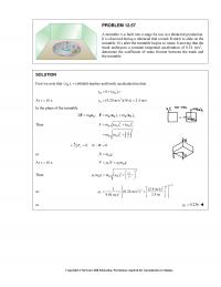
PROBLEM 12.57 A turntable A is built into a stage for use in a theatrical production. It is observed during a rehearsal that a trunk B starts to slide on the turntable 10 s after the turntable begins to rotate. […]
978-0073398242 Chapter 12 Solution Manual Part 11
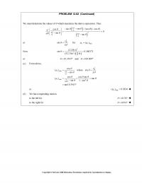
PROBLEM 12.62 (Continued) We must determine the values of which maximize the above expression. Thus 2 2 2 2 sin sin (cos )( cos ) cos 0 sin sin B B B g v gg vv […]
978-0073398242 Chapter 12 Solution Manual Part 12
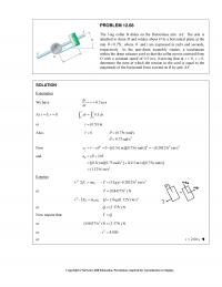
PROBLEM 12.68 The 3-kg collar B slides on the frictionless arm .AA The arm is attached to drum D and rotates about O in a horizontal plane at the rate 0.75 , t where […]
978-0073398242 Chapter 12 Solution Manual Part 13
PROBLEM 12.75 (Continued) Since the particle moves under a central force, 0. a Magnitude of acceleration. 2 22 0 2 0 rvr aaa r Tangential component of acceleration. 2 000 2 00 0 sin 2 tvr […]
978-0073398242 Chapter 12 Solution Manual Part 14
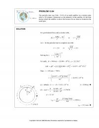
PROBLEM 12.84 The periodic time (see Prob. 12.83) of an earth satellite in a circular polar orbit is 120 minutes. Determine (a) the altitude h of the satellite, (b) the time during which the satellite is above the horizon for […]
978-0073398242 Chapter 12 Solution Manual Part 15
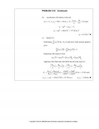
(b) Acceleration of B relative to the rod. At () 96 0, ( ) 8 ft/s 96 in./s, 9.6 rad/s 10 A AA v tv r 2() 0 BB Br rr a […]
978-0073398242 Chapter 12 Solution Manual Part 16
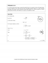
PROBLEM 12.101 It was observed that as the Voyager I spacecraft reached the point of its trajectory closest to the planet Saturn, it was at a distance of 3 185 10km from the center of the planet and had a […]
978-0073398242 Chapter 12 Solution Manual Part 17
PROBLEM 12.107 (Continued) (b) From Part (a), we have 2 sun 11 2() AA A B GM r v rr Then, for any other elliptic orbit about the sun, we have 211 2 12 […]
978-0073398242 Chapter 12 Solution Manual Part 18
PROBLEM 12.113 (Continued) Then 2 4 3 3 2 1or 2 28 3 8 6332 10 m 3 10,131.4 m/s 1666.63 s BA BA BA A A BA AA BA AA A A A ht t h r v h […]
978-0073398242 Chapter 12 Solution Manual Part 19
PROBLEM 12.121 Show that the angular momentum per unit mass h of a satellite describing an elliptic orbit of semimajor axis a and eccentricity about a planet of mass M can be expressed as SOLUTION By Eq. At A, At […]
978-0073398242 Chapter 12 Solution Manual Part 2
Copyright © McGraw-Hill Education. Permission required for reproduction or display. PROBLEM 12.7 (Continued) (b) From Kinematics: x x vdv adx vdv dx a 2 1 0 2.5 1 27000 3 33ln3 27000 | v x v mvdv dx […]
978-0073398242 Chapter 12 Solution Manual Part 20
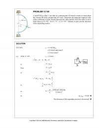
PROBLEM 12.128 A small 200-g collar C can slide on a semicircular rod which is made to rotate about the vertical AB at the constant rate of 6 rad/s. Determine the minimum required value of the coefficient of static friction […]
978-0073398242 Chapter 12 Solution Manual Part 21
PROBLEM 12.133* (Continued) and and at Note: implies that the slider remains at its initial radial position. With Eq. (2) implies (b) Substituting the given values into Eq. (1) Now Then so that At Now At 0 dr […]
978-0073398242 Chapter 12 Solution Manual Part 22
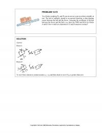
PROBLEM 12.F2 Two blocks weighing WA and WB are at rest on a conveyor that is initially at rest. The belt is suddenly started in an upward direction so that slipping occurs between the belt and the boxes. Assuming the […]
978-0073398242 Chapter 12 Solution Manual Part 3
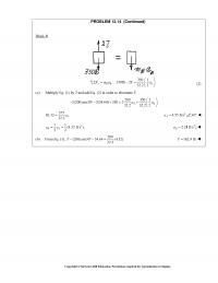
PROBLEM 12.14 (Continued) Block B 350 1 :350lb2 32.2 2 yBB A Fma T a (2) (a) Multiply Eq. (1) by 2 and add Eq. (2) in order to eliminate T: 200 350 1 […]
978-0073398242 Chapter 12 Solution Manual Part 4
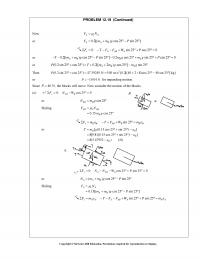
PROBLEM 12.19 (Continued) Now AsA FN or 0.2[( ) cos 25 sin 25 ] AAB Fmmg P 0: sin 25 cos 25 0 xAABA FTFFW P or 0.2[( ) cos 25 sin […]
978-0073398242 Chapter 12 Solution Manual Part 5
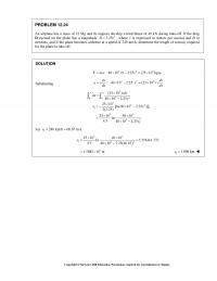
PROBLEM 12.24 An airplane has a mass of 25 Mg and its engines develop a total thrust of 40 kN during take-off. If the drag D exerted on the plane has a magnitude 2 2.25 , D v where v […]
978-0073398242 Chapter 12 Solution Manual Part 6
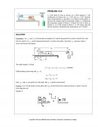
PROBLEM 12.31 A 10-lb block B rests as shown on a 20-lb bracket A. The coefficients of friction are 0.30 s and 0.25 k between block B and bracket A, and there is no friction in […]
978-0073398242 Chapter 12 Solution Manual Part 7
PROBLEM 12.36 A 450-g tetherball A is moving along a horizontal circular path at a constant speed of 4 m/s. Determine (a) the angle that the cord forms with pole BC, (b) the tension in the cord. SOLUTION First […]
978-0073398242 Chapter 12 Solution Manual Part 8
PROBLEM 12.43* (Continued) max max ( ) 16.9443 lb () 17lb DA DE T T Eq. (1) max 2 2 () (32.2 ft/s )(0.5 ft) ( ) (16.9443sin 20 17sin 30 ) lb 1.2 lb DA T v […]
978-0073398242 Chapter 12 Solution Manual Part 9
PROBLEM 12.50 (Continued) At B: 2 : B nnB v Fma N m or 22 22,555 m /s 54 kg 1200 m B N or 1014.98 N B N :|| tt B t FmaWPma or […]

978-0073398242 Chapter 13 Solution Manual Part 1
CHAPTER 13 PROBLEM 13.1 A 400–kg satellite is placed in a circular orbit 6394 km above the surface of the earth. At this elevation the acceleration of gravity is 2 4.09 m/s . Knowing that its orbital speed is 20 […]
978-0073398242 Chapter 13 Solution Manual Part 10
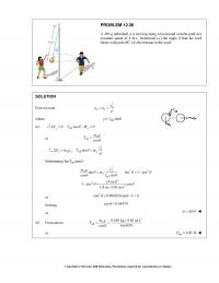
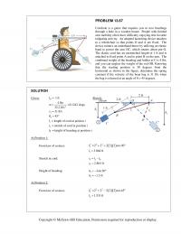
PROBLEM 13.67 Cornhole is a game that requires you to toss beanbags through a hole in a wooden board. People with limited arm mobility often have difficulty enjoying this favorite tailgating activity. An adapted launching device attaches to a wheelchair […]
978-0073398242 Chapter 13 Solution Manual Part 11
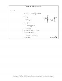
PROBLEM 13.72 (Continued) Forces at B. 0 2 2 ( ) (10) 6.6667 lb. 3 5 sin 13 5 5 in. ft 12 (0.031056)(205.72) 5/12 15.3332 lb sB B n Fk mv ma α ρ ρ = −= = […]
978-0073398242 Chapter 13 Solution Manual Part 12
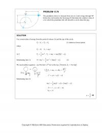
PROBLEM 13.78 The pendulum shown is released from rest at A and swings through 90° before the cord touches the fixed peg B. Determine the smallest value of a for which the pendulum bob will describe a circle about the […]
978-0073398242 Chapter 13 Solution Manual Part 2
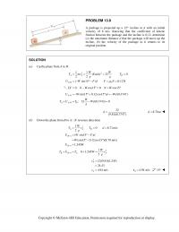
PROBLEM 13.9 A package is projected up a 15° incline at A with an initial velocity of 8 m/s. Knowing that the coefficient of kinetic friction between the package and the incline is 0.12, determine (a) the maximum distance d […]
978-0073398242 Chapter 13 Solution Manual Part 3
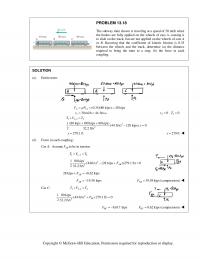
PROBLEM 13.18 The subway train shown is traveling at a speed of 30 mi/h when the brakes are fully applied on the wheels of cars A, causing it to slide on the track, but are not applied on the wheels […]
978-0073398242 Chapter 13 Solution Manual Part 4
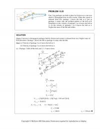
PROBLEM 13.25 Four 3–kg packages are held in place by friction on a conveyor which is disengaged from its drive motor. When the system is released from rest, package 1 leaves the belt at A just as package 4 comes […]
978-0073398242 Chapter 13 Solution Manual Part 5
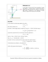
PROBLEM 13.31 A 5–kg collar A is at rest on top of, but not attached to, a spring with stiffness k1 = 400 N/m; when a constant 150–N force is applied to the cable. Knowing A has a speed of […]
978-0073398242 Chapter 13 Solution Manual Part 6
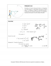
PROBLEM 13.39 The sphere at A is given a downward velocity 0 v of magnitude 5 m/s and swings in a vertical plane at the end of a rope of length 2ml= attached to a support at O. Determine the […]
978-0073398242 Chapter 13 Solution Manual Part 8
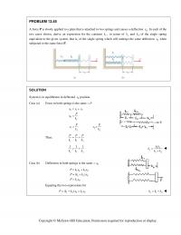
PROBLEM 13.55 A force P is slowly applied to a plate that is attached to two springs and causes a deflection 0 .x In each of the two cases shown, derive an expression for the constant , e k in […]
978-0073398242 Chapter 13 Solution Manual Part 9
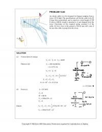
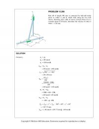
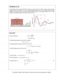
PROBLEM 13.62 An elastic cable is to be designed for bungee jumping from a tower 130 ft high. The specifications call for the cable to be 85 ft long when unstretched, and to stretch to a total length of 100 […]

978-0073398242 Chapter 14 Solution Manual Part 1
CHAPTER 14 PROBLEM 14.1 A 30-g bullet is fired with a horizontal velocity of 450 m/s and becomes embedded in block B which has a mass of 3 kg. After the impact, block B slides on 30-kg carrier C until […]
978-0073398242 Chapter 14 Solution Manual Part 10
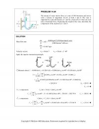
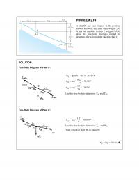
PROBLEM 14.64 The stream of water shown flows at a rate of 550 liters/min and moves with a velocity of magnitude 18 m/s at both A and B. The vane is supported by a pin and bracket at C and […]
978-0073398242 Chapter 14 Solution Manual Part 11
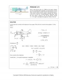
PROBLEM 14.73 Prior to take-off the pilot of a 3000-kg twin-engine airplane tests the reversible-pitch propellers by increasing the reverse thrust with the brakes at point B locked. Knowing that point G is the center of gravity of the airplane, […]
978-0073398242 Chapter 14 Solution Manual Part 12
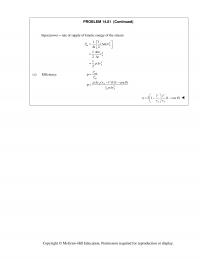
PROBLEM 14.81 (Continued) Input power rate of supply of kinetic energy of the stream 2 in 2 3 11 () 2 1 2 1 2 A A A P mv t mv t Av […]
978-0073398242 Chapter 14 Solution Manual Part 13
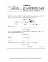
PROBLEM 14.89 A toy car is propelled by water that squirts from an internal tank at a constant 6 ft/s relative to the car. The weight of the empty car is 0.4 lb and it holds 2 lb of water. […]
978-0073398242 Chapter 14 Solution Manual Part 14
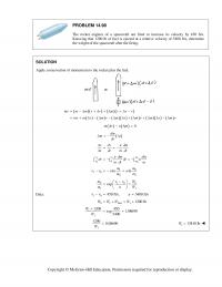
PROBLEM 14.98 The rocket engines of a spacecraft are fired to increase its velocity by 450 ft/s. Knowing that 1200 lb of fuel is ejected at a relative velocity of 5400 ft/s, determine the weight of the spacecraft after the […]
978-0073398242 Chapter 14 Solution Manual Part 15
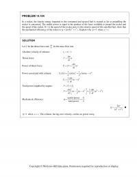
PROBLEM 14.104 In a rocket, the kinetic energy imparted to the consumed and ejected fuel is wasted as far as propelling the rocket is concerned. The useful power is equal to the product of the force available to propel the […]
978-0073398242 Chapter 14 Solution Manual Part 16
PROBLEM 14.110 (Continued) 112 2 :TV T V 2 0 27 0.10352 2.5 A v 22 236.67 ft A v 15.38 ft/s A v 5.13 ft/s B v Copyright © McGraw-Hill Education. Permission required for reproduction or […]
978-0073398242 Chapter 14 Solution Manual Part 2
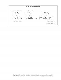
PROBLEM 14.7 (Continued) (c) Container slides and stops only after 2nd coupling 12 360 65 100vv 15.54 km/hv 23.60 km/hv Copyright © McGraw-Hill Education. Permission required for reproduction or display. PROBLEM 14.8 Two identical cars A and B […]
978-0073398242 Chapter 14 Solution Manual Part 3
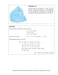
PROBLEM 14.13 A system consists of three particles A, B, and C. We know that 3 A m kg, 2 B m kg, and 4 C m kg and that the velocities of the particles expressed in m/s […]
978-0073398242 Chapter 14 Solution Manual Part 4
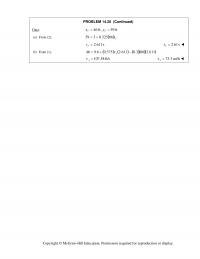
PROBLEM 14.20 (Continued) Data: ft 59 ft, 46 PP yx ( ) From (2),a P t66325.0359 s 611.2 P t s 61.2 P t ()From (1), b […]
978-0073398242 Chapter 14 Solution Manual Part 5
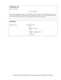
PROBLEM 14.27 Derive the relation OG m HrvH between the angular momenta O H and G H defined in Eqs. (14.7) and (14.24), respectively. The vectors r and v define, respectively, the position and velocity of the mass center G […]
978-0073398242 Chapter 14 Solution Manual Part 6
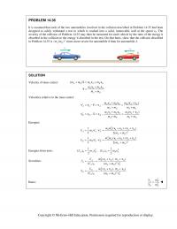
PROBLEM 14.36 It is assumed that each of the two automobiles involved in the collision described in Problem 14.35 had been designed to safely withstand a test in which it crashed into a solid, immovable wall at the speed v0. […]
978-0073398242 Chapter 14 Solution Manual Part 7
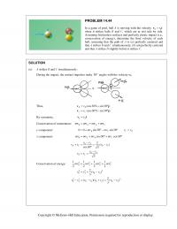
PROBLEM 14.44 In a game of pool, ball A is moving with the velocity 00 vvi when it strikes balls B and C, which are at rest side by side. Assuming frictionless surfaces and perfectly elastic impact (i.e., conservation of […]
978-0073398242 Chapter 14 Solution Manual Part 8
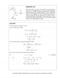
PROBLEM 14.50 Three small spheres A, B, and C, each of mass m, are connected to a small ring D of negligible mass by means of three inextensible, inelastic cords of length l. The spheres can slide freely on a […]
978-0073398242 Chapter 14 Solution Manual Part 9
PROBLEM 14.55 (Continued) Conservation of energy. Before break: 22 0 22 2 2 0 11 (3 ) 3 22 33 [(1.3) (2.6) ] 12.675 22 Tmv mv mv v m m […]
978-0073398242 Chapter 15 Solution Manual Part 10
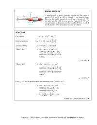
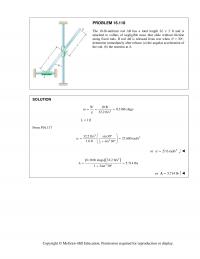
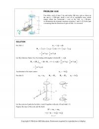
PROBLEM 15.73 A juggling club is thrown vertically into the air. The center of gravity G of the 20 in. club is located 12 in. from the knob. Knowing that at the instant shown G has a velocity of 4 […]
978-0073398242 Chapter 15 Solution Manual Part 11
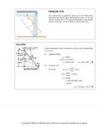
PROBLEM 15.82 An overhead door is guided by wheels at A and B that roll in horizontal and vertical tracks. Knowing that when 40 θ = ° the velocity of wheel B is 1.5 ft/s upward, determine (a) the angular […]
978-0073398242 Chapter 15 Solution Manual Part 12
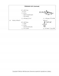
PROBLEM 15.90 (Continued) 487.97 mm 10.37 () (487.97 mm)(0.9 rad/s) 439.18 mm/s F CF v CF β ω = = ° = = = 439 mm/s F =v 10.4° 439 mm/s F =v 79.6° (b) Velocity of Point G: […]
978-0073398242 Chapter 15 Solution Manual Part 13
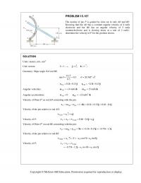
PROBLEM 15.97 At the instant shown, the velocity of collar A is 0.4 m/s to the right and the velocity of collar B is 1 m/s to the left. Determine (a) the angular velocity of bar AD, (b) the angular […]
978-0073398242 Chapter 15 Solution Manual Part 14
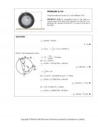
PROBLEM 15.104 Using the method of section 15.3, solve Problem 15.38. PROBLEM 15.38 An automobile travels to the right at a constant speed of 48 mi/h. If the diameter of a wheel is 22 in., determine the velocities of Points […]
978-0073398242 Chapter 15 Solution Manual Part 15
PROBLEM 15.117 (Continued) .Acceleration of Point D // ()() D A DA t DA n =++aa a a [ A a= 30 ] [r α °+ 2 60 ] [r ω °+ 30 ]° [720= 30 ] [(100)(7.2)°+ 2 60 […]
978-0073398242 Chapter 15 Solution Manual Part 16
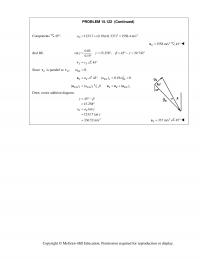
PROBLEM 15.122 (Continued) Components 45 :° 22 1233.7 (0.19)(41.337) 1558.4 m/s D a=+= 2 1558 m/s D =a 45° Rod BE. 0.05 sin , 15.258 , 45 29.742 0.19 γ γ βγ = = ° = °− = ° […]
978-0073398242 Chapter 15 Solution Manual Part 18
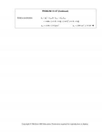
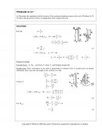
PROBLEM 15.127 (Continued) Relative acceleration: DE =aa ( ) ( ) ( ) 2 D/ D/ 2 1.466 0.12 0.8 1.463 0.12 0.8 DEF E DEF E αω + ×− = ×−−− −− kr r k ij ij 2 1.430 […]
978-0073398242 Chapter 15 Solution Manual Part 19
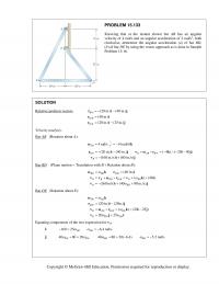
PROBLEM 15.133 Knowing that at the instant shown bar AB has an angular velocity of 4 rad/s and an angular acceleration of 2 rad/s2, both clockwise, determine the angular acceleration (a) of bar BD, (b) of bar DE by using […]
978-0073398242 Chapter 15 Solution Manual Part 2
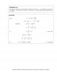
PROBLEM 15.8 The angular acceleration of an oscillating disk is defined by the relation . k αθ = − Determine (a) the value of k for which 12 ω = rad/s when 0 θ = and 6 θ = rad […]
978-0073398242 Chapter 15 Solution Manual Part 20
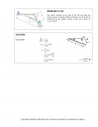
PROBLEM 15.139* The wheels attached to the ends of rod AB roll along the surfaces shown. Using the method of Section 15.4 B, derive an expression for the angular velocity of the rod in terms of , ,, B vl […]
978-0073398242 Chapter 15 Solution Manual Part 21
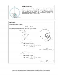
PROBLEM 15.148* A wheel of radius r rolls without slipping along the inside of a fixed cylinder of radius R with a constant angular velocity .ω Denoting by P the point of the wheel in contact with the cylinder at […]
978-0073398242 Chapter 15 Solution Manual Part 22
PROBLEM 15.157 The motion of pin P is guided by slots cut in rods AD and BE. Knowing that bar AD has a constant angular velocity of 4 rad/s clockwise and bar BE has an angular velocity of 5 rad/s […]
978-0073398242 Chapter 15 Solution Manual Part 23
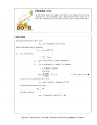
PROBLEM 15.164 At the instant shown the length of the boom AB is being decreased at the constant rate of 0.2 m/s and the boom is being lowered at the constant rate of 0.08 rad/s. Determine (a) the velocity of […]
978-0073398242 Chapter 15 Solution Manual Part 24
PROBLEM 15.170 (Continued) Coriolis acceleration: / 2 (2)(2 ) (1.18176 0.2084 ) W SE ×= × + Ωv k i j 0.8336 4.72704 =−+ ij Acceleration of W: // 2 1.00408 1.88176 W W W SE W SE ′ = […]
978-0073398242 Chapter 15 Solution Manual Part 25
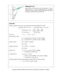
PROBLEM 15.176 Knowing that at the instant shown the rod attached at A has an angular velocity of 5 rad/s counterclockwise and an angular acceleration of 2 rad/s2 clockwise, determine the angular velocity and the angular acceleration of the rod […]
978-0073398242 Chapter 15 Solution Manual Part 26
PROBLEM 15.181* Rod AB passes through a collar that is welded to link DE. Knowing that at the instant shown block A moves to the right at a constant speed of 75 in./s, determine (a) the angular velocity of rod […]
978-0073398242 Chapter 15 Solution Manual Part 27
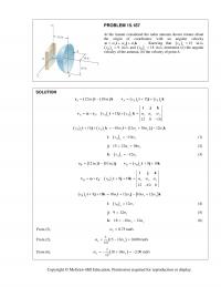
PROBLEM 15.187 At the instant considered the radar antenna shown rotates about the origin of coordinates with an angular velocity xyz ωωω =++ i jk ω . Knowing that ( ) 15 Ay v= in./s, () 9 By v= in./s, […]
978-0073398242 Chapter 15 Solution Manual Part 28
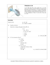
PROBLEM 15.195 A 3–in.–radius disk spins at the constant rate 2 4 ω = rad/s about an axis held by a housing attached to a horizontal rod that rotates at the constant rate 15 ω = rad/s. For the position […]
978-0073398242 Chapter 15 Solution Manual Part 29
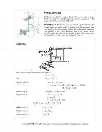
PROBLEM 15.202 In Problem 15.201 the speed of Point B is known to be constant. For the position shown, determine (a) the angular acceleration of the guide arm, (b) the acceleration of Point C. PROBLEM 15.201 Several rods are brazed […]
978-0073398242 Chapter 15 Solution Manual Part 3
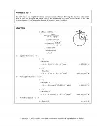
PROBLEM 15.17 The earth makes one complete revolution on its axis in 23 h 56 min. Knowing that the mean radius of the earth is 3960 mi, determine the linear velocity and acceleration of a point on the surface of […]
978-0073398242 Chapter 15 Solution Manual Part 30
PROBLEM 15.209 Rod AB of length 300 mm is connected by ball–and–socket joints to collars A and B, which slide along the two rods shown. Knowing that collar B moves toward Point D at a constant speed of 50 mm/s, […]
978-0073398242 Chapter 15 Solution Manual Part 32
PROBLEM 15.220 A flight simulator is used to train pilots on how to recognize spatial disorientation. It has four degrees of freedom, and can rotate around a planetary axis as well as in yaw, pitch, and roll. The pilot is […]
978-0073398242 Chapter 15 Solution Manual Part 33
PROBLEM 15.227 (Continued) (a) Velocity of Point D. / (0.75 m/s) (0.75 3 m/s) ( 3 m/s) D D DF D ′ = + =+− vvv v i jk (0.750 m/s) (1.299 m/s) (1.732 m/s) D =+−v ijk Coriolis […]
978-0073398242 Chapter 15 Solution Manual Part 34
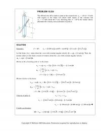
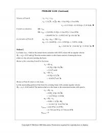
PROBLEM 15.234 The 400-mm bar AB is made to rotate at the constant rate 2 ω = / d dt θ = 8 rad/s with respect to the frame CD which itself rotates at the constant rate 1 ω = […]
978-0073398242 Chapter 15 Solution Manual Part 35
PROBLEM 15.239 (Continued) 2 0.25 (2.5 3 ) (0.625 3 m/s ) BB ′′ = × = × = − aΩv ji k Motion of Point B relative to the frame. Let the unextending portion of the boom be a […]
978-0073398242 Chapter 15 Solution Manual Part 36
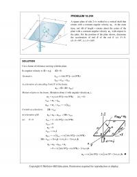
PROBLEM 15.244 A square plate of side 2r is welded to a vertical shaft that rotates with a constant angular velocity 1 .ω At the same time, rod AB of length r rotates about the center of the plate with […]
978-0073398242 Chapter 15 Solution Manual Part 37
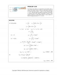
PROBLEM 15.249 Two blocks and a pulley are connected by inextensible cords as shown. The relative velocity of block A with respect to block B is 2.5 ft/s to the left at time t = 0 and 1.25 ft/s to […]
978-0073398242 Chapter 15 Solution Manual Part 38
PROBLEM 15.254 (Continued) (a) Angular acceleration of AB. 2 7.90 rad/s AB α = (b) Angular acceleration of the wheel. 2 () () 0 () ( 2.0187) 134.6 rad/s 0.015 Pt Bt BP Bt BP a ar a r […]
978-0073398242 Chapter 15 Solution Manual Part 39
PROBLEM 15.259 (Continued) Coriolis acceleration. / 2 2 (2)(1.2 ) ( 9 3 ) (7.2 in./s ) AF × = ×− + = v i ij k Ω Acceleration of Point A. // 2 8.64 12.96 9 13.5 7.2 A […]
978-0073398242 Chapter 15 Solution Manual Part 4
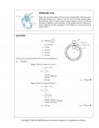
PROBLEM 15.26 Ring C has an inside radius of 55 mm and an outside radius of 60 mm and is positioned between two wheels A and B, each of 24–mm outside radius. Knowing that wheel A rotates with a constant […]
978-0073398242 Chapter 15 Solution Manual Part 5
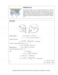
PROBLEM 15.33 Two friction wheels A and B are both rotating freely at 300 rpm counterclockwise when they are brought into contact. After 12 s of slippage, during which time each wheel has a constant angular acceleration, wheel B reaches […]
978-0073398242 Chapter 15 Solution Manual Part 6
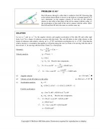
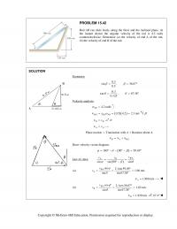
PROBLEM 15.42 Rod AB can slide freely along the floor and the inclined plane. At the instant shown the angular velocity of the rod is 4.2 rad/s counterclockwise. Determine (a) the velocity of end A of the rod, (b) the […]
978-0073398242 Chapter 15 Solution Manual Part 7
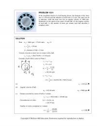
PROBLEM 15.51 In the simplified sketch of a ball bearing shown, the diameter of the inner race A is 60 mm and the diameter of each ball is 12 mm. The outer race B is stationary while the inner race […]
978-0073398242 Chapter 15 Solution Manual Part 8
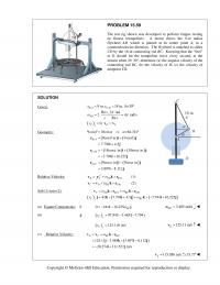
PROBLEM 15.59 The test rig shown was developed to perform fatigue testing on fitness trampolines. A motor drives the 9–in radius flywheel AB, which is pinned at its center point A, in a counterclockwise direction. The flywheel is attached to […]
978-0073398242 Chapter 15 Solution Manual Part 9
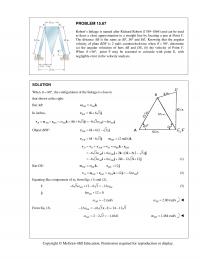
PROBLEM 15.67 Robert’s linkage is named after Richard Robert (1789–1864) and can be used to draw a close approximation to a straight line by locating a pen at Point F. The distance AB is the same as BF, DF and […]

978-0073398242 Chapter 16 Solution Manual Part 1
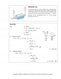
CHAPTER 16 PROBLEM 16.1 A 60–lb uniform thin panel is placed in a truck with end A resting on a rough horizontal surface and end B supported by a smooth vertical surface. Knowing that the deceleration of the truck is […]
978-0073398242 Chapter 16 Solution Manual Part 10
PROBLEM 16.59 The steel roll shown has a mass of 1200 kg, has a centriodal radius of gyration of 150 mm, and is lifted by two cables looped around its shaft. Knowing that at the instant shown the acceleration of […]
978-0073398242 Chapter 16 Solution Manual Part 11
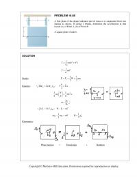
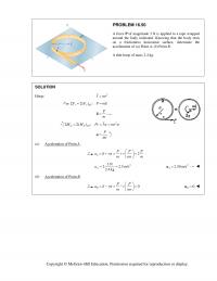
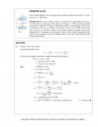
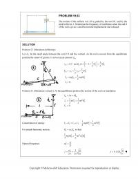
PROBLEM 16.66 A thin plate of the shape indicated and of mass m is suspended from two springs as shown. If spring 2 breaks, determine the acceleration at that instant (a) of Point A, (b) of Point B. A square […]
978-0073398242 Chapter 16 Solution Manual Part 12
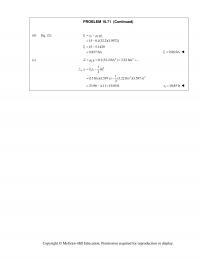
PROBLEM 16.71 (Continued) (b) Eq. (2): 10 1 15 0.1(32.2)(1.5972) k v v gt µ = − = − 9.857 ft/s = 1 9.86 ft/sv= (c) 22 0.1(32.2 ft/s ) 3.22 ft/s k ag µ = = = 2 […]
978-0073398242 Chapter 16 Solution Manual Part 13
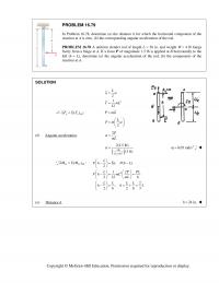
PROBLEM 16.79 In Problem 16.78, determine (a) the distance h for which the horizontal component of the reaction at A is zero, (b) the corresponding angular acceleration of the rod. PROBLEM 16.78 A uniform slender rod of length L = […]
978-0073398242 Chapter 16 Solution Manual Part 14
PROBLEM 16.87 (Continued) (b) Components of reaction of C. 2 eff ( ) : (1.5 kg)(14 m/s ) x x x AB n F F C maΣ=Σ =− =− 21.0 N x C= − 21.0 N x =C eff […]
978-0073398242 Chapter 16 Solution Manual Part 15
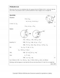
PROBLEM 16.93 Show that in the case of an unbalanced disk, the equation derived in Problem 16.92 is valid only when the mass center G, the geometric center O, and the instantaneous center C happen to lie in a straight […]
978-0073398242 Chapter 16 Solution Manual Part 16
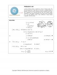
PROBLEM 16.100 A drum of 60–mm radius is attached to a disk of 120–mm radius. The disk and drum have a total mass of 6 kg and a combined radius of gyration of 90 mm. A cord is attached as […]
978-0073398242 Chapter 16 Solution Manual Part 18
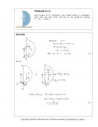
PROBLEM 16.112 Solve Problem 16.111, considering a half cylinder instead of a hemisphere. [Hint. Note that 4 /3 OG r π = and that, by the parallel–axis theorem, 22 1 2 ( ) .]I mr m OG= − SOLUTION Kinematics: […]
978-0073398242 Chapter 16 Solution Manual Part 19
PROBLEM 16.118 The 10–lb–uniform rod AB has a total length 2L = 2 ft and is attached to collars of negligible mass that slide without friction along fixed rods. If rod AB is released from rest when 30 , θ […]
978-0073398242 Chapter 16 Solution Manual Part 2
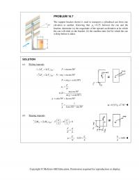
PROBLEM 16.7 The support bracket shown is used to transport a cylindrical can from one elevation to another. Knowing that 0.25 s µ = between the can and the bracket, determine (a) the magnitude of the upward acceleration a for […]
978-0073398242 Chapter 16 Solution Manual Part 20
PROBLEM 16.124 The 4–kg uniform rod ABD is attached to the crank BC and is fitted with a small wheel that can roll without friction along a vertical slot. Knowing that at the instant shown crank BC rotates with an […]
978-0073398242 Chapter 16 Solution Manual Part 21
PROBLEM 16.128 (Continued) Kinematics: =+× vvωr Equating i–terms: Relative Acceleration: Equating i components: (5) Equating j components: (6) Relative Acceleration: (7) (8) Substitute into (6)→(1): (9) BA =aa ω −+ra /A 2 3.2 B π × = − r j […]
978-0073398242 Chapter 16 Solution Manual Part 22
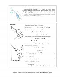
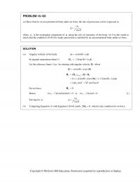
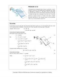
PROBLEM 16.133 For the car of Problem 16.132, determine the smallest constant acceleration that the driver can maintain if the door is to close and latch, knowing that as the door hits the frame its angular velocity must be at […]
978-0073398242 Chapter 16 Solution Manual Part 23
PROBLEM 16.136 (Continued) Effective couples at mass centers. Disk AB: (0.2)(150) AB AB I= α 30 N m= ⋅ Rod BC: (0.08)(149.649) BC BC I=α 11.97192 N m= ⋅ Rod CD: (0.0260417)(239.719) CD CD I=α 6.24268 N m= ⋅ Summary […]
978-0073398242 Chapter 16 Solution Manual Part 24
PROBLEM 16.141 (Continued) Rod AE: / , AE AE P AE u= =α αk a j // 2 P P P AE P AE ′ =+ +×aaa ωv where // 2 2 10 10 sin30 (20) sin30 12 12 […]
978-0073398242 Chapter 16 Solution Manual Part 25
PROBLEM 16.145 (Continued) Rod eff / ( ) : 0 ( ) ( cos25 ) 22 A A RGR RC LL M M I ma ma a Σ=Σ =+ − ° (1.50cos25 ) C a a = ° (2) (a) […]
978-0073398242 Chapter 16 Solution Manual Part 26
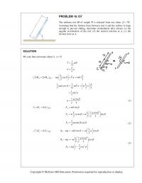
PROBLEM 16.151* (a) Determine the magnitude and the location of the maximum bending moment in the rod of Problem 16.78. (b) Show that the answer to Part a is independent of the weight of the rod. SOLUTION Rod AB: 2 […]
978-0073398242 Chapter 16 Solution Manual Part 27
PROBLEM 16.157 The uniform rod AB of weight W is released from rest when 70 . β = ° Assuming that the friction force between end A and the surface is large enough to prevent sliding, determine immediately after release […]
978-0073398242 Chapter 16 Solution Manual Part 28
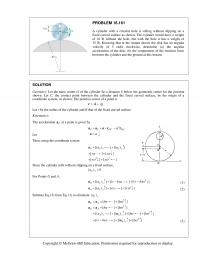
PROBLEM 16.161 A cylinder with a circular hole is rolling without slipping on a fixed curved surface as shown. The cylinder would have a weight of 16 lb without the hole, but with the hole it has a weight of […]
978-0073398242 Chapter 16 Solution Manual Part 29
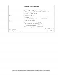
PROBLEM 16.164 (Continued) 12 32.2 ft/s 22 2 6 lb 1.5 ft (81.391 rad/s ) 0.23697 lb ft 0 since 0 ss DD I I a a = = ⋅ = […]
978-0073398242 Chapter 16 Solution Manual Part 3
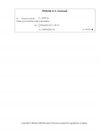
PROBLEM 16.13 (Continued) (b) Tension in link AB. 89525 A F mg= Taking mg to be half the weight of the machine, 2 1(20 kg)(9.81 m/s ) 98.1 N 2 mg = = (0.89522)(98.1 N) A F= 87.8 NF= […]
978-0073398242 Chapter 16 Solution Manual Part 30
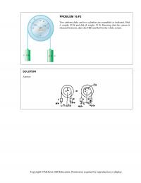
PROBLEM 16.F3 Two uniform disks and two cylinders are assembled as indicated. Disk A weighs 20 lb and disk B weighs 12 lb. Knowing that the system is released from rest, draw the FBD and KD for the whole system. […]
978-0073398242 Chapter 16 Solution Manual Part 4
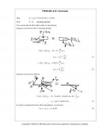
PROBLEM 16.20 (Continued) Thus, 0.50 (22.5 lb) 11.25 lb ms FN µ = = = Since , the block will slide m FF> Now assume that the block slides relative to the platform. Equations of motion for block: (assuming sliding) […]
978-0073398242 Chapter 16 Solution Manual Part 5
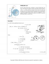
PROBLEM 16.27 The 8–in.–radius brake drum is attached to a larger flywheel that is not shown. The total mass moment of inertia of the drum and the flywheel is 2 14 lb ft s⋅⋅ and the coefficient of kinetic friction […]
978-0073398242 Chapter 16 Solution Manual Part 6
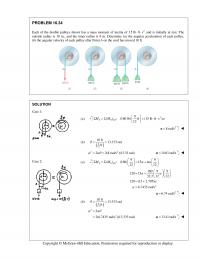
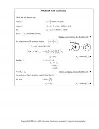
PROBLEM 16.34 Each of the double pulleys shown has a mass moment of inertia of 2 15 lb ft s⋅⋅ and is initially at rest. The outside radius is 18 in., and the inner radius is 9 in. Determine (a) […]
978-0073398242 Chapter 16 Solution Manual Part 7
PROBLEM 16.39 (Continued) Check that belt does not slip. From (2): 5(0.864) 0.720 lb 6 A F= = From (4): 3.60 0.720 2.88 lb eA F PF=−= − = But 0.50(5 lb) 2.50 lb ms FN µ = = = […]
978-0073398242 Chapter 16 Solution Manual Part 8
PROBLEM 16.44 (Continued) When disks have stopped slipping: 0 (2 ) 2 P AA BB B Ak k A vrr m r g t gt m ωω ωµ µ = = −= 0 0 1 21 2 B A Am […]
978-0073398242 Chapter 16 Solution Manual Part 9
PROBLEM 16.50 A force P of magnitude 3 N is applied to a tape wrapped around the body indicated. Knowing that the body rests on a frictionless horizontal surface, determine the acceleration of (a) Point A, (b) Point B. A […]

978-0073398242 Chapter 17 Solution Manual Part 1
CHAPTER 17 PROBLEM 17.1 A 200-kg flywheel is at rest when a constant 300 N m couple is applied. After executing 560 revolutions, the flywheel reaches its rated speed of 2400 rpm. Knowing that the radius of gyration of […]
978-0073398242 Chapter 17 Solution Manual Part 10
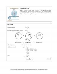
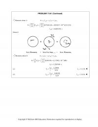
PROBLEM 17.58 Disk A, of weight 5 lb and radius 3in.,r is at rest when it is placed in contact with a belt which moves at a constant speed 50 ft/s.v Knowing that 0.20 k between the disk […]
978-0073398242 Chapter 17 Solution Manual Part 11
PROBLEM 17.64 (Continued) Moments about A: 0 AAB AA A A rT t rTt I 6 0.9 0.9 0 ( ) (0.75)(0.24) (169.837 10 )(133.333) 12 12 0.48193 lb s AB AB Tt Tt […]
978-0073398242 Chapter 17 Solution Manual Part 12
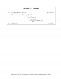
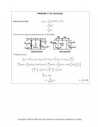
PROBLEM 17.71 (Continued) (a) (0.150)(17.0077) 2.55115 m/sv 2.55 m/sv Linear components: 0 P t mgt Qt mv (3)(2.55115) (3)(9.81) 24 1.5 mv QmgP t (b) Tension in cord C. 10.53 NQ Copyright © McGraw-Hill […]
978-0073398242 Chapter 17 Solution Manual Part 13
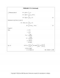
PROBLEM 17.76 (Continued) Moments about B: 2 (4 ) 1 4( ) (4 ) 12 ABC ABC Mt Qt r I Mt Qt r m r 2 4( ) 3ABC M tQtrmr (2) 4 […]
978-0073398242 Chapter 17 Solution Manual Part 14
PROBLEM 17.83 (Continued) Moments about C: 2 .5359 rad/s 11 1/1 2 2 2/2 22 /1 1 /2 2 22 2 2 2 () () [0.0025 0.30 (1.6)(0.0625) ](5) [0.0025 0.30 (1.6)(0.4375) ] (0.30875)(5) 0.60875 AB DCE AB G […]
978-0073398242 Chapter 17 Solution Manual Part 15
PROBLEM 17.89 (Continued) Solving the quadratic equation for , I 0.04965167 0.126590 0.050804 and 0.022179 3.46904 I Reject the negative root. From Equation (10), 2(21)(0.050804) 0.378 0.050804 0.02592 18.83 rad/s 2 0.0508 kg […]
978-0073398242 Chapter 17 Solution Manual Part 16
PROBLEM 17.94 (Continued) Kinetic energy. / AB DCE AB G C r II mrv 222 22222 22 2 1 11 1 22 2 111 (0.0025)(5) (0.3)(5) (1.6)(0.0625) 0 3.859375 J T 11 […]
978-0073398242 Chapter 17 Solution Manual Part 17
PROBLEM 17.100 (Continued) Principle of impulse and momentum. 1 Syst. Momenta 12 Syst. Ext. Imp. 2 Syst. Momenta Moments about A: 1222 22 ( ) ft 0 ( ) (0.95015 ft) ft 12 12 4lb 7 4lb […]
978-0073398242 Chapter 17 Solution Manual Part 18
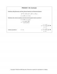
PROBLEM 17.106 (Continued) Substitute rolling Kinematics and Mass Moment Equations into Momentum Equation: cm 22 r2cosvr cm v rm 23 rm 23 cos 1 cvcr 3 rr Substitute in the velocity at position […]
978-0073398242 Chapter 17 Solution Manual Part 19
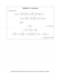
PROBLEM 17.112 (Continued) moments about B: 00 0 t mv mv L mv L mL L I 22 211 224 422 L 22 00 mv L m […]
978-0073398242 Chapter 17 Solution Manual Part 2
PROBLEM 17.8 (Continued) 12 5.886 2 36.983 N m BB k k UM Principle of work and energy for cylinder B. 2 1122 : 0 36.983 0.0225 kB TU T […]
978-0073398242 Chapter 17 Solution Manual Part 20
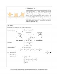
PROBLEM 17.118 A uniformly loaded square crate is released from rest with its corner D directly above A; it rotates about A until its corner B strikes the floor, and then rotates about B. The floor is sufficiently rough to […]
978-0073398242 Chapter 17 Solution Manual Part 21
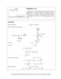
PROBLEM 17.123 A slender rod AB is released from rest in the position shown. It swings down to a vertical position and strikes a second and identical rod CD which is resting on a frictionless surface. Assuming that the coefficient […]
978-0073398242 Chapter 17 Solution Manual Part 22
PROBLEM 17.127 (Continued) Coefficient of restitution. 4 () ev v DAD D A L vvv 0.1875 (0.5)(3 0) D v (2) Solving Eqs. (1) and (2) simultaneously. […]
978-0073398242 Chapter 17 Solution Manual Part 23
PROBLEM 17.132 (Continued) Add Equations (1) and (2) to eliminate .Pdt 11 or AB BA mv mv mv v v v (3) Condition of impact. 1. e 11BA vvevv (4) Solving Equations (3) and (4) simultaneously, 1 0, […]
978-0073398242 Chapter 17 Solution Manual Part 24
PROBLEM 17.137 (Continued) Kinetics: (b) (c) Work Energy Equation Pos. 1 and 3: 0 OO M I tTt tT F ma Omy 0 t O 2 2 12 31.91 90.7 2.8168 5.993 […]
978-0073398242 Chapter 17 Solution Manual Part 25
PROBLEM 17.142 (Continued) Panel in down position ( ) (2 )[ (2 ) ] Itbbb 22 2 panel 1 4 4 12 10 12 5 tb 1 6 tb Conservation of angular momentum about […]
978-0073398242 Chapter 17 Solution Manual Part 26
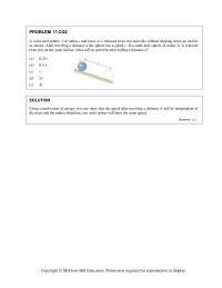
PROBLEM 17.CQ2 A solid steel sphere A of radius r and mass m is released from rest and rolls without slipping down an incline as shown. After traveling a distance d the sphere has a speed v. If a solid […]
978-0073398242 Chapter 17 Solution Manual Part 3
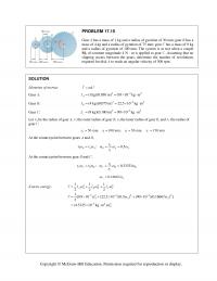
PROBLEM 17.15 Gear A has a mass of 1 kg and a radius of gyration of 30 mm; gear B has a mass of 4 kg and a radius of gyration of 75 mm; gear C has a mass of […]
978-0073398242 Chapter 17 Solution Manual Part 4
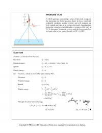
PROBLEM 17.20 A 160-lb gymnast is executing a series of full-circle swings on the horizontal bar. In the position shown he has a small and negligible clockwise angular velocity and will maintain his body straight and rigid as he swings […]
978-0073398242 Chapter 17 Solution Manual Part 5
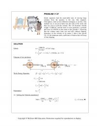
PROBLEM 17.27 Greek engineers had the unenviable task of moving large columns from the quarries to the city. One engineer, Chersiphron, tried several different techniques to do this. One method was to cut pivot holes into the ends of the […]
978-0073398242 Chapter 17 Solution Manual Part 6
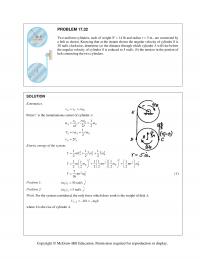
PROBLEM 17.32 Two uniform cylinders, each of weight W 14 lb and radius r 5 in., are connected by a belt as shown. Knowing that at the instant shown the angular velocity of cylinder B is 30 rad/s […]
978-0073398242 Chapter 17 Solution Manual Part 7
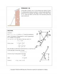
PROBLEM 17.38 A long ladder of length l, mass m, and centroidal mass moment of inertia I is placed against a house at an angle . Knowing that the ladder is released from rest, determine the angular […]
978-0073398242 Chapter 17 Solution Manual Part 8
PROBLEM 17.42 (Continued) By Eq. (2), 22 2 2 735 kg m 21.096 J 12 12 AB AB mL 222 7.2329 rad /s 2.6894 rad/s AB AB By Eq. (1), (1m)(2.6894 rad/s) […]
978-0073398242 Chapter 17 Solution Manual Part 9
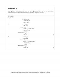
PROBLEM 17.48 Knowing that the maximum allowable couple that can be applied to a shaft is 15.5 kip in., determine the maximum horsepower that can be transmitted by the shaft at (a) 180 rpm, (b) 480 rpm. SOLUTION 15.5 […]

978-0073398242 Chapter 18 Solution Manual Part 1
CHAPTER 18 PROBLEM 18.1 A thin, homogeneous disk of mass m and radius r spins at the constant rate 1 about an axle held by a fork-ended vertical rod, which rotates at the constant rate 2. Determine the […]
978-0073398242 Chapter 18 Solution Manual Part 10
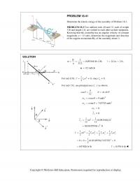
PROBLEM 18.64 Determine the rate of change G H of the angular momentum H G of the disk of Prob. 18.8 for an arbitrary value of , knowing that the disk has an angular velocity = […]
978-0073398242 Chapter 18 Solution Manual Part 11
PROBLEM 18.68 (Continued) Then 2 22 2 2 () () () () 2 22 2 2 2 (2)(1)(0.2) (12) 14.4 N 4(4)(0.2) 0, 14.4 N xz z yzz aa a a I ma m a m a ma ma ma […]
978-0073398242 Chapter 18 Solution Manual Part 12
PROBLEM 18.73 (Continued) For calculation of , x z I use pairs of elements 1 dA and 2 :dA 21 dA dA 2 121 0 (4 ) (2 ) (2 ) 22 […]
978-0073398242 Chapter 18 Solution Manual Part 13
PROBLEM 18.77 (Continued) (b) Reactions at and for the case 0.AB 2 x yxzyz xz M cA I I I 63 (187.5 10 )(12) 15 10 N 0.150 xz y I Ac […]
978-0073398242 Chapter 18 Solution Manual Part 14
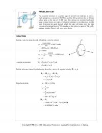
PROBLEM 18.84 The essential structure of a certain type of aircraft turn indicator is shown. Each spring has a constant of 500 N/m, and the 200-g uniform disk of 40-mm radius spins at the rate of 10,000 rpm. The springs […]
978-0073398242 Chapter 18 Solution Manual Part 15
PROBLEM 18.89 (Continued) Let the reference frame Dxyz be rotating with angular velocity 1. 11 0sin cos GG G xxyy Gxyz II HH Ηi j i j […]
978-0073398242 Chapter 18 Solution Manual Part 16
PROBLEM 18.95 Two disks, each of mass 5 kg and radius 300 mm, spin as shown at the rate 11200 rpm about a rod AB of negligible mass which rotates about the horizontal z axis at the rate […]
978-0073398242 Chapter 18 Solution Manual Part 17
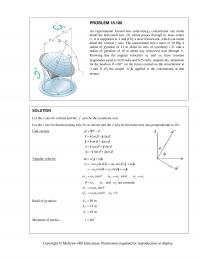
PROBLEM 18.100 An experimental Fresnel-lens solar-energy concentrator can rotate about the horizontal axis AB, which passes through its mass center G. It is supported at A and B by a steel framework, which can rotate about the vertical y axis. […]
978-0073398242 Chapter 18 Solution Manual Part 18
PROBLEM 18.104 (Continued) Resolve into components. 2 22 2 22 / 2222 02222 2 2( ) ( ) ( ) ( ) EEAAE AA A xy A l D D M mbl cl mcl bl mb c […]
978-0073398242 Chapter 18 Solution Manual Part 19
PROBLEM 18.109 The 85-g top shown is supported at the fixed Point O. The radii of gyration of the top with respect to its axis of symmetry and with respect to a transverse axis through O are 21 mm and […]
978-0073398242 Chapter 18 Solution Manual Part 2
PROBLEM 18.7 (Continued) For each plate parallel to the xy plane: 1 5 mm 2 222 177 a 2 222 22 2 2 151 (2 ) 12 2 12 60 x I ma m ma ma […]
978-0073398242 Chapter 18 Solution Manual Part 20
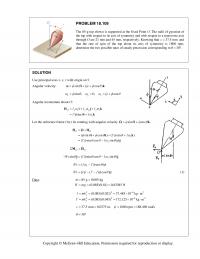
PROBLEM 18.114 A homogeneous cone of height h = 12 in. and with a base diameter d = 6 in. is attached as shown to a cord AB. Knowing that the angles that cord AB and the axis BC of […]
978-0073398242 Chapter 18 Solution Manual Part 21
PROBLEM 18.120 (a) Show that for an axisymmetrical body under no force, the rate of precession can be expressed as cos z I I where z is the rectangular component of ω along the […]
978-0073398242 Chapter 18 Solution Manual Part 22
PROBLEM 18.128 Solve Sample Problem 18.6, assuming that the meteorite strikes the satellite at C with a velocity 0(2000 m/s) .vi PROBLEM 18.6 A space satellite of mass m is known to be dynamically equivalent to two thin disks of […]
978-0073398242 Chapter 18 Solution Manual Part 23
PROBLEM 18.132 A homogeneous rectangular plate of mass m and sides c and 2c is held at A and B by a fork-ended shaft of negligible mass which is supported by a bearing at C. The plate is free to […]
978-0073398242 Chapter 18 Solution Manual Part 24
PROBLEM 18.137* The top shown is supported at the fixed Point O. Denoting by ,, and the Eulerian angles defining the position of the top with respect to a fixed frame of reference, consider the general motion […]
978-0073398242 Chapter 18 Solution Manual Part 25
PROBLEM 18.141* (Continued) Given data: 217 011 g a Substituting into Eq. (6), 22 11 11 sin aa Letting 22 cos 1 sin , we have 2 sin 1.7sin 1 […]
978-0073398242 Chapter 18 Solution Manual Part 26
PROBLEM 18.147 Three 25-lb rotor disks are attached to a shaft which rotates at 720 rpm. Disk A is attached eccentrically so that its mass center is 1 4in. from the axis of rotation, while disks B and C are […]
978-0073398242 Chapter 18 Solution Manual Part 27
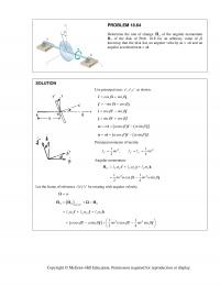
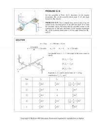
PROBLEM 18.153 A homogeneous disk of weight 6 lb W rotates at the constant rate 1 16 rad/s with respect to arm ABC, which is welded to a shaft DCE rotating at the constant rate 2 8 rad/s. […]
978-0073398242 Chapter 18 Solution Manual Part 28
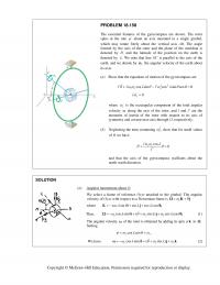
PROBLEM 18.158 The essential features of the gyrocompass are shown. The rotor spins at the rate about an axis mounted in a single gimbal, which may rotate freely about the vertical axis AB. The angle formed by the […]
978-0073398242 Chapter 18 Solution Manual Part 3
PROBLEM 18.16 For the assembly of Prob. 18.15, determine ( a ) the angular momentum B H of the assembly about point B , ( b ) the angle formed by B H and BA . PROBLEM 18.15: Two L-shaped […]
978-0073398242 Chapter 18 Solution Manual Part 4
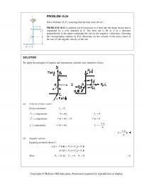
PROBLEM 18.24 Solve Problem 18.23, assuming that the bent rod is hit at C . PROBLEM 18.23 A uniform rod of total mass m is bent into the shape shown and is suspended by a wire attached at B . […]
978-0073398242 Chapter 18 Solution Manual Part 5
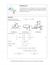
PROBLEM 18.29 A circular plate of mass m is falling with a velocity 0 v and no angular velocity when its edge C strikes an obstruction. Assuming the impact to be perfectly plastic (0),e determine the angular velocity of the […]
978-0073398242 Chapter 18 Solution Manual Part 6
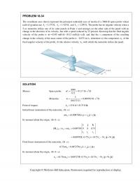
PROBLEM 18.34 The coordinate axes shown represent the principal centroidal axes of inertia of a 3000-lb space probe whose radii of gyration are 1.375 ft, x k 1.425 ft, y k and 1.250 ft. z k The probe has no […]
978-0073398242 Chapter 18 Solution Manual Part 7
PROBLEM 18.41 Determine the kinetic energy of the assembly of Problem 18.3. PROBLEM 18.3 Two uniform rods AB and CE, each of weight 3 lb and length 2 ft, are welded to each other at their midpoints. Knowing that this […]
978-0073398242 Chapter 18 Solution Manual Part 8
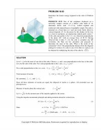
PROBLEM 18.50 Determine the kinetic energy imparted to the cube of Problem 18.21. PROBLEM 18.21 One of the sculptures displayed on a university campus consists of a hollow cube made of six aluminum sheets, each 1.5 1.5 m, welded […]
978-0073398242 Chapter 18 Solution Manual Part 9
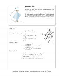
PROBLEM 18.56 Determine the rate of change G H of the angular momentum G H of the plate of Problem 18.2. PROBLEM 18.2 A thin rectangular plate of weight 15 lb rotates about its vertical diagonal AB with an […]

978-0073398242 Chapter 19 Solution Manual Part 1
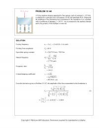
CHAPTER 19 PROBLEM 19.1 A particle moves in simple harmonic motion. Knowing that the maximum velocity is 200 mm/s and the maximum acceleration is 4 m/s2, determine the amplitude and frequency of the motion. SOLUTION Eq. 19.15: 2 mmn mmn […]
978-0073398242 Chapter 19 Solution Manual Part 10
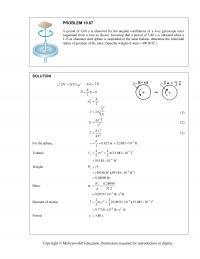
S O O LUTION PROB L A perio d suspend e 1.25-in.- d radius o f ( MM Σ=Σ L EM 19.67 d of 6.00 s is e d from a wir e d iameter steel f gyration of t […]
978-0073398242 Chapter 19 Solution Manual Part 11
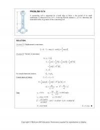
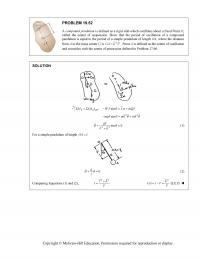
PROBLEM 19.74 A connecting rod is supported by a knife edge at Point A; the period of its small oscillations is observed to be 1.03 s. Knowing that the distance ra is 6 in. determine the centroidal radius of gyration […]
978-0073398242 Chapter 19 Solution Manual Part 12
PROBLEM 19.80 (Continued) Conservation of energy. 222 22 2 11 2 2 0 11 1 1 1 :00 22 3 2 2 2 AB m m AB m l TV T V mr ml kr mg θ θθ ⎛⎞ +=+ […]
978-0073398242 Chapter 19 Solution Manual Part 13
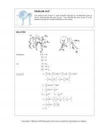
SO Ki n LUTION n ematics: PR O Tw o sho w dete r O BLEM 1 9 o uniform rod s w n. Knowing r mine the per i 2 2 2 A AC AC rr θθ θ θ […]
978-0073398242 Chapter 19 Solution Manual Part 14
PROBLEM 19.93 The motion of the uniform rod AB is guided by the cord BC and by the small roller at A. Determine the frequency of oscillation when the end B of the rod is given a small horizontal displacement […]
978-0073398242 Chapter 19 Solution Manual Part 15
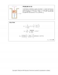
PROBLEM 19.102 A 64-lb block is attached to a spring of constant 1kip/ftk= and can move without friction in a vertical slot as shown. It is acted upon by a periodic force of magnitude sin , mf P Pt ω […]
978-0073398242 Chapter 19 Solution Manual Part 16
PROBLEM 19.109 (Continued) Then 2 224 22 112 1 0and 2 0and 2 nn ff ωω ωω == ⎜⎟ ⎜⎟ ⎝⎠ ⎝⎠ ⎛⎞ == ⎜⎟ fff nnn ff nn ωω ⎛⎞ ⎛⎞ ⎝⎠ ωωω ωωω ωω ⎡⎤ ⎛⎞ ⎛⎞⎛⎞ ⎢⎥ […]
978-0073398242 Chapter 19 Solution Manual Part 17
PROBLEM 19.116 (Continued) Out of phase motion with | | 0.06 in. m x= 0.00125 0.06 0.06 <− ⎜⎟ ⎜⎟ ( ) () 2 2 22 2 ff nn ωω ωω ⎛⎞ ⎛⎞ ⎝⎠ ⎝⎠ 0.00125 0.06 1 0.06 0.05875 […]
978-0073398242 Chapter 19 Solution Manual Part 18
SO G d Th u f ω 2 n kr ω kr r 2 () f mr e km m ω =+ = = 2 2 2 2 2 () 1 n f n n kre e ω ω ω […]
978-0073398242 Chapter 19 Solution Manual Part 19
PROBLEM 19.132 A loaded railroad car weighing 30,000 lb is rolling at a constant velocity v0 when it couples with a spring and dashpot bumper system (Figure 1). The recorded displacement-time curve of the loaded railroad car after coupling is […]
978-0073398242 Chapter 19 Solution Manual Part 2
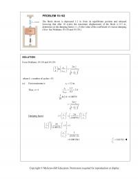
PROBLEM 19.9 A 10-lb block A rests on a 40-lb plate B which is attached to an unstretched spring of constant k = 60 lb/ft. Plate B is slowly moved 2.4 in. to the left and released from rest. Assuming […]
978-0073398242 Chapter 19 Solution Manual Part 20
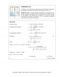
PROBLEM 19.140 In Problem 19.139, determine the required value of the coefficient of damping if the amplitude of the steady-state vibration of the element is to be 0.15 in. PROBLEM 19.139 A machine element weighing 800 lb is supported by […]
978-0073398242 Chapter 19 Solution Manual Part 21
PROBLEM 19.148 A 91-kg machine element supported by four springs, each of constant k = 175 N/m, is subjected to a periodic force of frequency 0.8 Hz and amplitude 89 N. Determine the amplitude of the fluctuating force transmitted to […]
978-0073398242 Chapter 19 Solution Manual Part 22
(b) R ⎝ e ⎟⎜ ⎟ ⎠⎝ ⎠ L ⎜⎟ ⎝⎠ Copyrig h ht © McGra w w -Hill Educ a a tion. Permis s s ion require d d for reprodu ction or display. Rearrangi n Substitute n g […]
978-0073398242 Chapter 19 Solution Manual Part 23
PROBLEM 19.162 The block shown is depressed 1.2 in. from its equilibrium position and released. Knowing that after 10 cycles the maximum displacement of the block is 0.5 in., determine (a) the damping factor c/c, (b) the value of the […]
978-0073398242 Chapter 19 Solution Manual Part 24
PROBLEM 19.166 (Continued) Amplitude of vibration. Use Eq. (19.53). () () () 22 2 12 1 m f f cn n P k m c c x ω ω ω ω = ⎡⎤ ⎡ ⎤ + − ⎢⎥ ⎢ ⎥ […]
978-0073398242 Chapter 19 Solution Manual Part 3
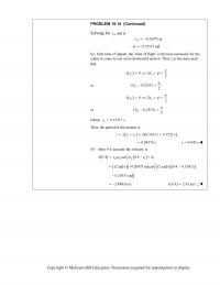
Copyright © McGraw-Hill Education. Permission required for reproduction or display. PROBLEM 19.15 (Continued) Solving for and m x φ 0.26975 m m x=− 0.25531 rad φ = − So, from time of impact, the ‘time of flight’ is the time […]
978-0073398242 Chapter 19 Solution Manual Part 4
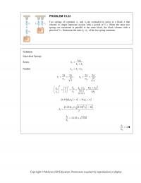
PROBLEM 19.23 Two springs of constants 1 k and 2 kare connected in series to a block A that vibrates in simple harmonic motion with a period of 5 s. When the same two springs are connected in parallel to […]
978-0073398242 Chapter 19 Solution Manual Part 5
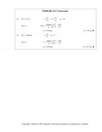
PROBLEM 19.31 (Continued) (a) For 0.5 s: τ = 22 ;0.5 4 τ ωπ === n nn ωω π π Eq. (1): 2 22(600) 0.5 9.81 (4 ) 0.7 0.7m π ⎛⎞ =− ⎜⎟ ⎝⎠ 3.561 kgm = 3.56 kgm […]
978-0073398242 Chapter 19 Solution Manual Part 6
S O Copyrig h ht © McGra w w -Hill Educ a a tion. Permis s s ion require d d for reprodu ction or disp lay. O LUTION PROB A 6-kg u and is a t is attac h […]
978-0073398242 Chapter 19 Solution Manual Part 7
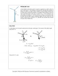
PROBLEM 19.46 A three-bladed wind turbine used for research is supported on a shaft so that it is free to rotate about O. One technique to determine the centroidal mass moment of inertia of an object is to place a […]
978-0073398242 Chapter 19 Solution Manual Part 8
SO For a simple pen d d ulum of leng t t h ,OA l= g 22 rk + Co m Copyrig h m paring Equa t ht © McGra w t ions (1) and ( w -Hill Educ […]
978-0073398242 Chapter 19 Solution Manual Part 9
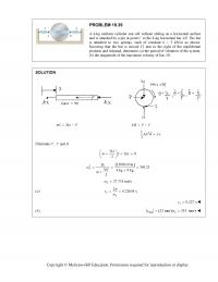
PROBLEM 19.60 (Continued) (b) When the disk is riveted at A, it rotates at an angular acceleration . α Equation of motion. 2 eff 1 (): sin , ,sin 2 BB t MM mgl IlmaImr θ αθθ Σ=Σ − =+ […]

978-0073398242 Chapter 2 Solution Manual Part 1
CHAPTER 2 PROBLEM 2.1 Two forces are applied as shown to a hook. Determine graphically the magnitude and direction of their resultant using (a) the parallelogram law, (b) the triangle rule. SOLUTION (a) Parallelogram law: (b) Triangle rule: We measure: […]
978-0073398242 Chapter 2 Solution Manual Part 10
PROBLEM 2.89 A rectangular plate is supported by three cables as shown. Knowing that the tension in cable AB is 408 N, determine the components of the force exerted on the plate at B. SOLUTION We have: (320 mm) (480 […]
978-0073398242 Chapter 2 Solution Manual Part 11
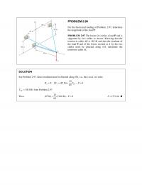
PROBLEM 2.98 For the boom and loading of Problem. 2.97, determine the magnitude of the load P. PROBLEM 2.97 The boom OA carries a load P and is supported by two cables as shown. Knowing that the tension in cable […]
978-0073398242 Chapter 2 Solution Manual Part 12
PROBLEM 2.104 (Continued) Equilibrium condition: 0: (36 lb) 0 DA DB DC FΣ= + + + =TTT j DA DB DC Substituting the expressions obtained for , , and DA DB DC TT T and factoring i, j, and k: […]
978-0073398242 Chapter 2 Solution Manual Part 13
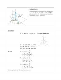
PROBLEM 2.111 A transmission tower is held by three guy wires attached to a pin at A and anchored by bolts at B, C, and D. If the tension in wire AB is 840 lb, determine the vertical force P […]
978-0073398242 Chapter 2 Solution Manual Part 14
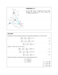
PROBLEM 2.117 For the cable system of Problems 2.107 and 2.108, determine the tension in each cable knowing that 2880 NP= and 576 N.Q= SOLUTION See Problem 2.116 for the analysis leading to the linear algebraic Equations (1), (2), and […]
978-0073398242 Chapter 2 Solution Manual Part 15
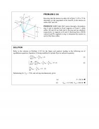
PROBLEM 2.124 Knowing that the tension in cable AE of Prob. 2.123 is 75 lb, determine (a) the magnitude of the load P, (b) the tension in cables BAC and AD. PROBLEM 2.123 Cable BAC passes through a frictionless ring […]
978-0073398242 Chapter 2 Solution Manual Part 16
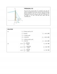
PROBLEM 2.133 The end of the coaxial cable AE is attached to the pole AB, which is strengthened by the guy wires AC and AD. Knowing that the tension in wire AC is 120 lb, determine (a) the components of […]
978-0073398242 Chapter 2 Solution Manual Part 17
PROBLEM 2.F4 A chairlift has been stopped in the position shown. Knowing that each chair weighs 250 N and that the skier in chair E weighs 765 N, draw the free–body diagrams needed to determine the weight of the skier […]
978-0073398242 Chapter 2 Solution Manual Part 2
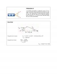
PROBLEM 2.9 A disabled automobile is pulled by means of two ropes as shown. Knowing that the tension in rope AB is 3 kN, determine by trigonometry the tension in rope AC and the value of α so that the […]
978-0073398242 Chapter 2 Solution Manual Part 3
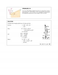
PROBLEM 2.19 Two forces P and Q are applied to the lid of a storage bin as shown. Knowing that P = 48 N and Q = 60 N, determine by trigonometry the magnitude and direction of the resultant of […]
978-0073398242 Chapter 2 Solution Manual Part 4
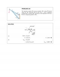
PROBLEM 2.29 The hydraulic cylinder BD exerts on member ABC a force P directed along line BD. Knowing that P must have a 750–N component perpendicular to member ABC, determine (a) the magnitude of the force P, (b) its component […]
978-0073398242 Chapter 2 Solution Manual Part 5
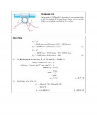
PROBLEM 2.39 For the collar of Problem 2.35, determine (a) the required value of α if the resultant of the three forces shown is to be vertical, (b) the corresponding magnitude of the resultant. SOLUTION (100 N)cos (150 N)cos( 30 […]
978-0073398242 Chapter 2 Solution Manual Part 6
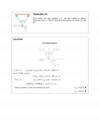
PROBLEM 2.49 Two cables are tied together at C and are loaded as shown. Knowing that P = 300 N, determine the tension in cables AC and BC. SOLUTION Free–Body Diagram 0 sin30 sin30 cos45 200N 0 x CA CB […]
978-0073398242 Chapter 2 Solution Manual Part 7
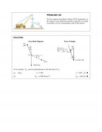
PROBLEM 2.59 For the situation described in Figure P2.48, determine (a) the value of α for which the tension in rope BC is as small as possible, (b) the corresponding value of the tension. SOLUTION Free–Body Diagram Force Triangle To […]
978-0073398242 Chapter 2 Solution Manual Part 8
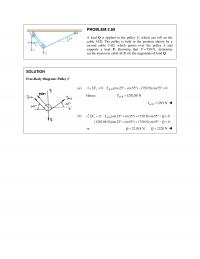
PROBLEM 2.69 A load Q is applied to the pulley C, which can roll on the cable ACB. The pulley is held in the position shown by a second cable CAD, which passes over the pulley A and supports a […]
978-0073398242 Chapter 2 Solution Manual Part 9
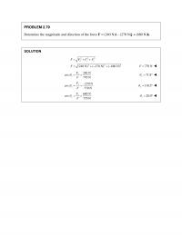
PROBLEM 2.79 Determine the magnitude and direction of the force F = (240 N)i – (270 N)j + (680 N)k. SOLUTION 222 222 (240 N) ( 270 N) ( 680 N) xyz F FFF F = ++ = +− +− […]
978-0073398242 Chapter 3 Solution Manual Part 1
CHAPTER 3 PROBLEM 3.1 A crate of mass 80 kg is held in the position shown. Determine (a) the moment produced by the weight W of the crate about E, (b) the smallest force applied at B that creates a […]
978-0073398242 Chapter 3 Solution Manual Part 10
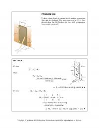
PROBLEM 3.86 A worker tries to move a rock by applying a 360–N force to a steel bar as shown. If two workers attempt to move the same rock by applying a force at A and a parallel force at […]
978-0073398242 Chapter 3 Solution Manual Part 11
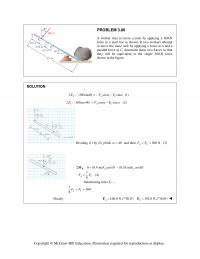
PROBLEM 3.96 To keep a door closed, a wooden stick is wedged between the floor and the doorknob. The stick exerts at B a 175–N force directed along line AB. Replace that force with an equivalent force–couple system at C. […]
978-0073398242 Chapter 3 Solution Manual Part 12
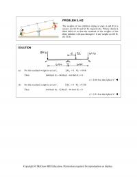
PROBLEM 3.105 The weights of two children sitting at ends A and B of a seesaw are 84 lb and 64 lb, respectively. Where should a third child sit so that the resultant of the weights of the three children […]
978-0073398242 Chapter 3 Solution Manual Part 13
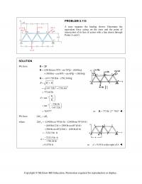
PROBLEM 3.113 A truss supports the loading shown. Determine the equivalent force acting on the truss and the point of intersection of its line of action with a line drawn through Points A and G. SOLUTION We have (240 lb)(cos70 […]
978-0073398242 Chapter 3 Solution Manual Part 14
PROBLEM 3.122 In order to unscrew the tapped faucet A, a plumber uses two pipe wrenches as shown. By exerting a 40–lb force on each wrench, at a distance of 10 in. from the axis of the pipe and in […]
978-0073398242 Chapter 3 Solution Manual Part 15
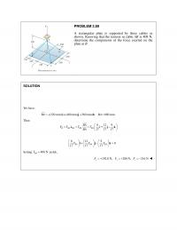
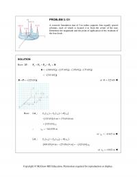
PROBLEM 3.131 A concrete foundation mat of 5–m radius supports four equally spaced columns, each of which is located 4 m from the center of the mat. Determine the magnitude and the point of application of the resultant of the […]
978-0073398242 Chapter 3 Solution Manual Part 16
PROBLEM 3.138* Two bolts at A and B are tightened by applying the forces and couples shown. Replace the two wrenches with a single equivalent wrench and determine (a) the resultant R, (b) the pitch of the single equivalent wrench, […]
978-0073398242 Chapter 3 Solution Manual Part 17
PROBLEM 3.142* (Continued) Substituting ? 160 ( 42 18 8 ) ( 3 ) 0 11 − + − ⋅ −− + =i j k ij k or ? 160 [( 42)( 1) (18)( 1) ( 8)(3)] 0 11 − […]
978-0073398242 Chapter 3 Solution Manual Part 18
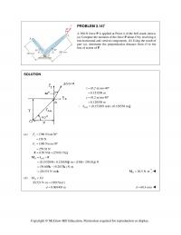
PROBLEM 3.147 A 300–N force P is applied at Point A of the bell crank shown. (a) Compute the moment of the force P about O by resolving it into horizontal and vertical components. (b) Using the result of part […]
978-0073398242 Chapter 3 Solution Manual Part 19
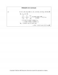
PROBLEM 3.156 (Continued) (b) 21 (42 42 49 ) N== +−FF i j k or 2 (42.0 N) (42.0 N) (49.0 N)=+−F ijk 2 /11 2 (0.1350) 0.03 0.07 0.31 0.0233 0 (31 N m) 0.155000 42 42 49 […]
978-0073398242 Chapter 3 Solution Manual Part 2
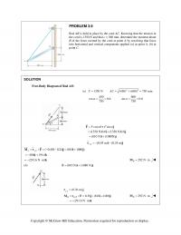
PROBLEM 3.9 Rod AB is held in place by the cord AC. Knowing that the tension in the cord is 1350 N and that c = 360 mm, determine the moment about B of the force exerted by the cord […]

978-0073398242 Chapter 3 Solution Manual Part 3
PROBLEM 3.19 Determine the moment about the origin O of the force F = 4i − 3j + 5k that acts at a Point A. Assume that the position vector of A is (a) r = 2i + 3j − […]
978-0073398242 Chapter 3 Solution Manual Part 4
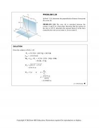
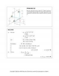
PROBLEM 3.29 In Prob. 3.24, determine the perpendicular distance from point B to wire AE. PROBLEM 3.24 The wire AE is stretched between the corners A and E of a bent plate. Knowing that the tension in the wire is […]
978-0073398242 Chapter 3 Solution Manual Part 5
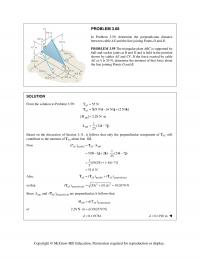
PROBLEM 3.39 Knowing that the tension in cable AC is 280 lb, determine (a) the angle between cable AC and the boom AB, (b) the projection on AB of the force exerted by cable AC at point A. SOLUTION (a) […]
978-0073398242 Chapter 3 Solution Manual Part 6
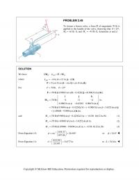
PROBLEM 3.49 To loosen a frozen valve, a force F of magnitude 70 lb is applied to the handle of the valve. Knowing that 25 , θ = ° Mx 61lb ft,=−⋅ and 43 lb ft, z M=−⋅ determine φ […]
978-0073398242 Chapter 3 Solution Manual Part 7
PROBLEM 3.58 In Problem 3.57, determine the moment about the diagonal AD of the force exerted on the frame by portion BG of the cable. PROBLEM 3.57 The frame ACD is hinged at A and D and is supported by […]
978-0073398242 Chapter 3 Solution Manual Part 8
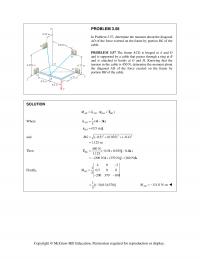
PROBLEM 3.68 In Problem 3.59, determine the perpendicular distance between cable AE and the line joining Points D and B. PROBLEM 3.59 The triangular plate ABC is supported by ball–and–socket joints at B and D and is held in the […]
978-0073398242 Chapter 3 Solution Manual Part 9
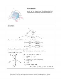
PROBLEM 3.78 Replace the two couples shown with a single equivalent couple, specifying its magnitude and the direction of its axis. SOLUTION Replace the couple in the ABCD plane with two couples P and Q shown: 160 mm (50 N) […]

978-0073398242 Chapter 4 Solution Manual Part 1
CHAPTER 4 PROBLEM 4.1 A gardener uses a 60-N wheelbarrow to transport a 250-N bag of fertilizer. What force must she exert on each handle? SOLUTION Free-Body Diagram: 0: (2 )(1m) (60 N)(0.15 m) (250 N)(0.3 m) 0 […]
978-0073398242 Chapter 4 Solution Manual Part 10
PROBLEM 4.76 Solve Problem 4.75, assuming that the 170-N force applied at B is horizontal and directed to the left. PROBLEM 4.75 Rod AB is supported by a pin and bracket at A and rests against a frictionless peg at […]
978-0073398242 Chapter 4 Solution Manual Part 11
PROBLEM 4.85 An 8-kg slender rod of length L is attached to collars that can slide freely along the guides shown. Knowing that the rod is in equilibrium and that 30, determine (a) the angle that the […]
978-0073398242 Chapter 4 Solution Manual Part 12
PROBLEM 4.94 A 48–ft sheet of plywood weighing 34 lb has been temporarily placed among three pipe supports. The lower edge of the sheet rests on small collars at A and B and its upper edge leans against pipe C. […]
978-0073398242 Chapter 4 Solution Manual Part 13
PROBLEM 4.103 The 24-lb square plate shown is supported by three vertical wires. Determine (a) the tension in each wire when 10a in., (b) the value of a for which the tension in each wire is 8 lb. SOLUTION […]
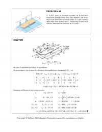
978-0073398242 Chapter 4 Solution Manual Part 14
PROBLEM 4.108 (Continued) From Eq. (2): 0.92857(2.80) 2.600 kN AD T 2.60 kN AD T 0.8 0.8 0: (2.6 kN) (2.8 kN) 0 0 2.6 2.8 0.6 1.2 0: (2.6 kN) (2.8 kN) (3.6 kN) 0 1.800 kN 2.6 […]
978-0073398242 Chapter 4 Solution Manual Part 15
PROBLEM 4.113 (Continued) 0.90 0.88182(19.6203 N) 0; 19.2240 N xx AA j: 0.90 44.145 0.180(19.6203 N) 0; 45.123 N yy AA i: 19.62 N CD F (19.22N) (45.1 N) Aij 0: cos11.5370 0 19.2240 19.6203cos11.5370 0 0 […]
978-0073398242 Chapter 4 Solution Manual Part 16
PROBLEM 4.118 (Continued) 0: 0 CE FABTW Coefficient of i: 270 (621.31) 0 855 x A 196.2 N x A Coefficient of j: 675 113.186 (621.31) 981 0 855 y A 377.3 N y A Coefficient of k: […]
978-0073398242 Chapter 4 Solution Manual Part 17
PROBLEM 4.124 Solve Problem 4.123, assuming that the 1.8- kN load is applied at C. PROBLEM 4.123 The rigid L-shaped member ABC is supported by a ball-and- socket joint at A and by three cables. If a 1.8- kN load […]
978-0073398242 Chapter 4 Solution Manual Part 18
PROBLEM 4.129 (Continued) 0: ( ) ( ) 0 xxCFBExDGx FATTT 12 24 600 N 975 N 625 N 0 13 25 x A 2100 N x A 0: ( ) […]
978-0073398242 Chapter 4 Solution Manual Part 19
PROBLEM 4.134 (Continued) // (0.5 m) ; (1 m) ; (268 N) BA CA ririPj To eliminate the reactions at A and D, we shall write /// 0: ( ) ( ) ( ) 0 AD AD B A BG […]
978-0073398242 Chapter 4 Solution Manual Part 2
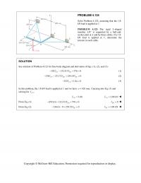
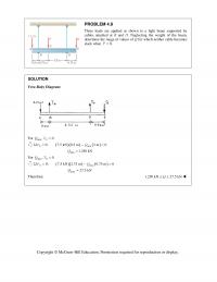
PROBLEM 4.9 Three loads are applied as shown to a light beam supported by cables attached at B and D. Neglecting the weight of the beam, determine the range of values of Q for which neither cable becomes slack when […]
978-0073398242 Chapter 4 Solution Manual Part 20
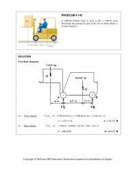
PROBLEM 4.142 A 3200-lb forklift truck is used to lift a 1700-lb crate. Determine the reaction at each of the two (a) front wheels A, (b) rear wheels B. SOLUTION Free-Body Diagram: (a) Front wheels: 0: (1700 lb)(52 in.) (3200 […]
978-0073398242 Chapter 4 Solution Manual Part 21
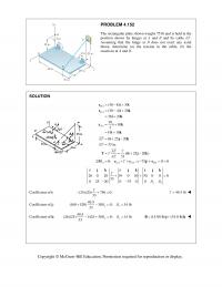
PROBLEM 4.152 The rectangular plate shown weighs 75 lb and is held in the position shown by hinges at A and B and by cable EF. Assuming that the hinge at B does not exert any axial thrust, determine (a) […]
978-0073398242 Chapter 4 Solution Manual Part 3
PROBLEM 4.19 The bracket BCD is hinged at C and attached to a control cable at B. For the loading shown, determine (a) the tension in the cable, (b) the reaction at C. SOLUTION At B: 0.18 m 0.24 m […]
978-0073398242 Chapter 4 Solution Manual Part 4
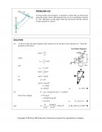
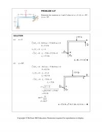
PROBLEM 4.27 Determine the reactions at A and B when (a) 0, (b) 90, (c) 30. SOLUTION (a) 0 0: (20 in.) 75 lb(10 in.) 0 37.5 lb A MB B […]
978-0073398242 Chapter 4 Solution Manual Part 5
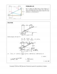
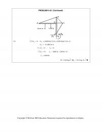
PROBLEM 4.35 Bar AC supports two 400-N loads as shown. Rollers at A and C rest against frictionless surfaces and a cable BD is attached at B. Determine (a) the tension in cable BD, (b) the reaction at A, (c) […]
978-0073398242 Chapter 4 Solution Manual Part 6
PROBLEM 4.43 (Continued) (b) 0: (3600 lb)(12 ft) (1200 lb)(6.5 ft) 0 EE MM 51,000 lb ft E M 00 xx FE 0: 3600 lb 1200 lb 0 yy FE […]
978-0073398242 Chapter 4 Solution Manual Part 7
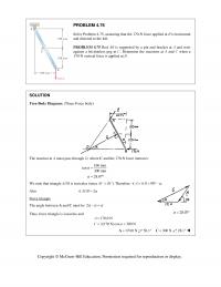
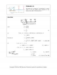
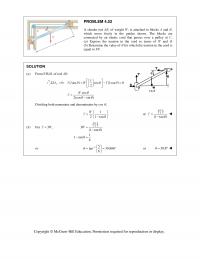
PROBLEM 4.53 A slender rod AB, of weight W, is attached to blocks A and B, which move freely in the guides shown. The blocks are connected by an elastic cord that passes over a pulley at C. (a) Express […]
978-0073398242 Chapter 4 Solution Manual Part 8
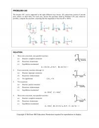
PROBLEM 4.60 The bracket ABC can be supported in the eight different ways shown. All connections consist of smooth pins, rollers, or short links. For each case, answer the questions listed in Problem 4.59, and, wherever possible, compute the reactions, […]
978-0073398242 Chapter 4 Solution Manual Part 9
PROBLEM 4.68 (Continued) Force Triangle Law of sines: 150 lb sin 29.745 sin116.565 sin33.690 CD 270.42 lb, 167.704 lb C D 270 lbC 56.3 ; 167.7 lbD26.6 Copyright © McGraw-Hill Education. Permission required for reproduction […]

978-0073398242 Chapter 5 Solution Manual Part 1
CHAPTER 5 PROBLEM 5.1 Locate the centroid of the plane area shown. SOLUTION Area 1: Rectangle 72 mm by 45 mm. Area 2: Triangle b = 27 mm, h = 45 mm. 2 ,mmA ,mm x ,mm y 3 ,mmxA […]
978-0073398242 Chapter 5 Solution Manual Part 10
PROBLEM 5.75 Determine (a) the distance a so that the reaction at support B is minimum, (b) the corresponding reactions at the supports. SOLUTION (a) We have I II 1( m)(1800 N/m) 900 N 2 1[(4 )m](600 N/m) 300(4 ) […]
978-0073398242 Chapter 5 Solution Manual Part 11
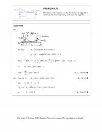
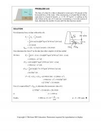
PROBLEM 5.83 The base of a dam for a lake is designed to resist up to 120 percent of the horizontal force of the water. After construction, it is found that silt (that is equivalent to a liquid of density […]
978-0073398242 Chapter 5 Solution Manual Part 12
PROBLEM 5.92 (Continued) Then with 0 y B (as explained above), we have 22 2184 1 0: (0.4) (0.25 ) 0 3 3 15 15 3 2 Ad Mdgdhgd […]
978-0073398242 Chapter 5 Solution Manual Part 13
PROBLEM 5.98 (Continued) (b) ?when 0.4 hYa a Substituting into Eq. (1) 2 3 (0.4)4 4 8 hh aa aa or 2 33.20.80 hh aa […]
978-0073398242 Chapter 5 Solution Manual Part 14
PROBLEM 5.106 Locate the center of gravity of the sheet-metal form shown. SOLUTION First assume that the sheet metal is homogeneous so that the center of gravity of the form will coincide with the centroid of the corresponding area. Now […]
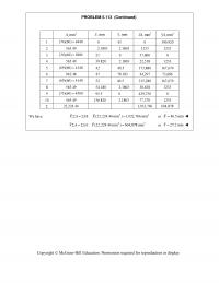
978-0073398242 Chapter 5 Solution Manual Part 15
PROBLEM 5.113 (Continued) 2 ,mmA ,mm x ,mm y 3 ,mmxA 3 ,mmyA 1 (74)(60) 4440 0 43 0 190,920 2 565.49 2.1803 2.1803 1233 1233 3 (30)(60) 1800 21 0 37,800 0 4 565.49 39.820 2.1803 22,518 1233 5 […]
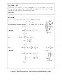
978-0073398242 Chapter 5 Solution Manual Part 16
PROBLEM 5.122 Determine by direct integration the values of x for the two volumes obtained by passing a vertical cutting plane through the given shape of Figure 5.21. The cutting plane is parallel to the base of the given shape […]
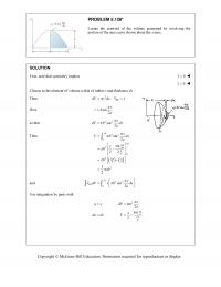
978-0073398242 Chapter 5 Solution Manual Part 17
PROBLEM 5.128* Locate the centroid of the volume generated by revolving the portion of the sine curve shown about the x-axis. SOLUTION First, note that symmetry implies 0y 0z Choose as the element of volume a disk of […]
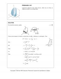
978-0073398242 Chapter 5 Solution Manual Part 18
PROBLEM 5.134* Locate the centroid of the section shown, which was cut from an elliptical cylinder by an oblique plane. SOLUTION First note that symmetry implies 0x Choose as the element of volume a vertical slice of width zx, […]
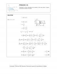
978-0073398242 Chapter 5 Solution Manual Part 19
PROBLEM 5.140 Determine by direct integration the centroid of the area shown. Express your answer in terms of a and h. SOLUTION 3 (1 )yh kx For ,0.xay 3 0(1 )hka 3 1 ka 3 3 1x yh a […]
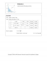
978-0073398242 Chapter 5 Solution Manual Part 2
PROBLEM 5.9 Locate the centroid of the plane area shown. SOLUTION Area 1: Square 75 mm by 75 mm. Area 2: Quarter circle radius of 75 mm. 2 ,mmA ,mm x ,mm y 3 ,mmxA 3 ,mmyA 1 75 75 […]
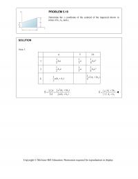
978-0073398242 Chapter 5 Solution Manual Part 3
PROBLEM 5.18 Determine the x coordinate of the centroid of the trapezoid shown in terms of h1, h2, and a. SOLUTION Area 1: A x x A 1 1 1 2ha 1 3a 2 1 1 6ha 2 2 1 […]
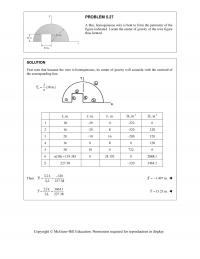
978-0073398242 Chapter 5 Solution Manual Part 4
PROBLEM 5.27 A thin, homogeneous wire is bent to form the perimeter of the figure indicated. Locate the center of gravity of the wire figure thus formed. SOLUTION First note that because the wire is homogeneous, its center of gravity […]
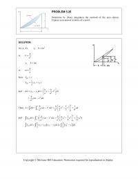
978-0073398242 Chapter 5 Solution Manual Part 5
PROBLEM 5.35 Determine by direct integration the centroid of the area shown. Express your answer in terms of a and h. SOLUTION At (, ),ah 1 :yhka or 2 h ka 2 :yhma or h ma Now 12 […]
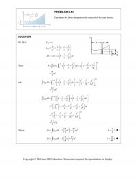
978-0073398242 Chapter 5 Solution Manual Part 6
PROBLEM 5.42 Determine by direct integration the centroid of the area shown . SOLUTION We have 2 2 2 2 11 22 1 EL EL xx axx yy LL xx dA ydx a dx LL […]
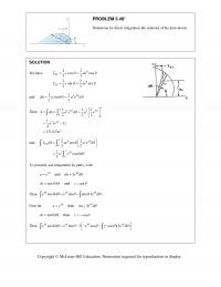
978-0073398242 Chapter 5 Solution Manual Part 7
PROBLEM 5.48* Determine by direct integration the centroid of the area shown. SOLUTION We have 22 cos cos 33 22 sin sin 33 EL EL xr ae yr ae and 22 11 ()( ) […]
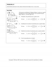
978-0073398242 Chapter 5 Solution Manual Part 8
PROBLEM 5.57 Verify that the expressions for the volumes of the first four shapes in Fig. 5.21 are correct. SOLUTION Following the second theorem of Pappus-Guldinus, in each case, a specific generating area A will be rotated about the x-axis […]
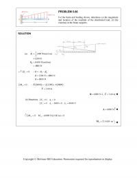
978-0073398242 Chapter 5 Solution Manual Part 9
PROBLEM 5.66 For the beam and loading shown, determine (a) the magnitude and location of the resultant of the distributed load, (b) the reactions at the beam supports. SOLUTION I II 1 ( ) (400 N/m) (6 m) 2 1200 […]
978-0073398242 Chapter 6 Solution Manual Part 1
CHAPTER 6 PROBLEM 6.1 Using the method of joints, determine the force in each member of the truss shown. State whether each member is in tension or compression. SOLUTION Free body: Entire truss: 0: 0 0 yy y FB […]

978-0073398242 Chapter 6 Solution Manual Part 10
PROBLEM 6.55 A monosloped roof truss is loaded as shown. Determine the force in members CE, DE, and DF. SOLUTION Reactions at supports: Because of the symmetry of the loading, 0 11 (Total load) (8 kN) 22 x y A […]
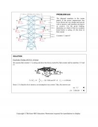
978-0073398242 Chapter 6 Solution Manual Part 11
PROBLEM 6.65 The diagonal members in the center panels of the power transmission line tower shown are very slender and can act only in tension; such members are known as counters. For the given loading, determine (a) which of the […]
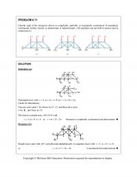
978-0073398242 Chapter 6 Solution Manual Part 12
PROBLEM 6.71 Classify each of the structures shown as completely, partially, or improperly constrained; if completely constrained, further classify as determinate or indeterminate. (All members can act both in tension and in compression.) SOLUTION Structure (a): Nonsimple truss with 4,r12,m […]
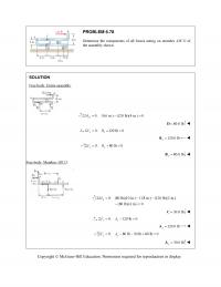
978-0073398242 Chapter 6 Solution Manual Part 13
PROBLEM 6.78 Determine the components of all forces acting on member ABCD of the assembly shown. SOLUTION Free body: Entire assembly: 0: (6 in.) (120 lb)(4 in.) 0 B MD 80.0 lb D 0: 120 lb 0 […]
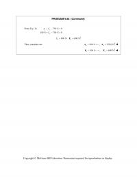
978-0073398242 Chapter 6 Solution Manual Part 14
PROBLEM 6.85 (Continued) From Eq. (1): 750 N 0 150 N 750 N 0 yy y AE E 600 N 600 N yy EE Thus, reactions are 300 N x A , 150.0 N y […]
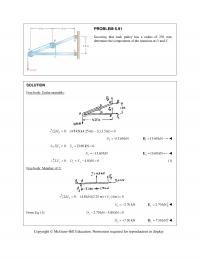
978-0073398242 Chapter 6 Solution Manual Part 15
PROBLEM 6.91 Knowing that each pulley has a radius of 250 mm, determine the components of the reactions at D and E. SOLUTION Free body: Entire assembly: 0: (4.8 kN)(4.25 m) (1.5 m) 0 Ex MD 13.60 kN […]
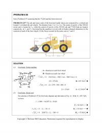
978-0073398242 Chapter 6 Solution Manual Part 16
PROBLEM 6.98 Solve Problem 6.97 assuming that the 75-kN load has been removed. PROBLEM 6.97 The cab and motor units of the front-end loader shown are connected by a vertical pin located 2 m behind the cab wheels. The distance […]
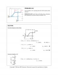
978-0073398242 Chapter 6 Solution Manual Part 17
PROBLEM 6.104 Solve Problem 6.103 assuming that the 360-lb load has been removed. PROBLEM 6.103 For the frame and loading shown, determine the components of all forces acting on member ABD. SOLUTION Free body diagram of entire frame. 0: (12 […]
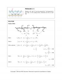
978-0073398242 Chapter 6 Solution Manual Part 18
PROBLEM 6.111 Members ABC and CDE are pin-connected at C and supported by four links. For the loading shown, determine the force in each link. SOLUTION Member FBDs: I II FBD I: 1 0: 0 2 2 B y AF […]
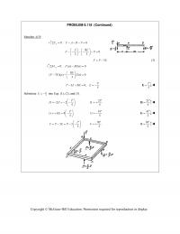
978-0073398242 Chapter 6 Solution Manual Part 19
Copyright © McGraw-Hill Education. Permission required for reproduction or display. PROBLEM 6.118 (Continued) Member AFB: 0: 0 y FFABP 80 33 EE FP 3FP E (3) 0: ( ) […]
978-0073398242 Chapter 6 Solution Manual Part 2
PROBLEM 6.5 (Continued) Joint C: 1 0: 10 kips 0 5 yCA FF 22.4 kips CA F 22.4 kips CA FT 2 0: (22.4 kips) 40 kips 0 5 xCB FF 60.0 kips CB […]
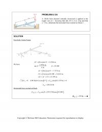
978-0073398242 Chapter 6 Solution Manual Part 20
Copyright © McGraw-Hill Education. Permission required for reproduction or display. PROBLEM 6.124 A 100-lb force directed vertically downward is applied to the toggle vise at C. Knowing that link BD is 6 in. long and that a = 8 in., […]
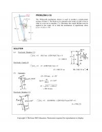
978-0073398242 Chapter 6 Solution Manual Part 21
PROBLEM 6.133 The Whitworth mechanism shown is used to produce a quick-return motion of Point D. The block at B is pinned to the crank AB and is free to slide in a slot cut in member CD. Determine the […]
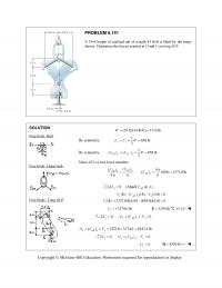
978-0073398242 Chapter 6 Solution Manual Part 22
PROBLEM 6.141 A 39-ft length of railroad rail of weight 44 lb/ft is lifted by the tongs shown. Determine the forces exerted at D and F on tong BDF. SOLUTION Free body: Rail: Free body: Upper link: Free Body: Tong […]
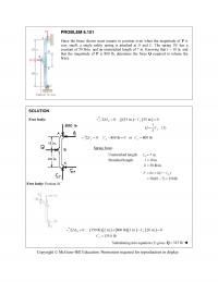
978-0073398242 Chapter 6 Solution Manual Part 23
PROBLEM 6.151 Since the brace shown must remain in position even when the magnitude of P is very small, a single safety spring is attached at D and E. The spring DE has a constant of 50 lb/in. and an […]
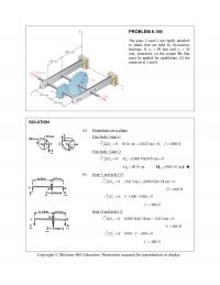
978-0073398242 Chapter 6 Solution Manual Part 24
PROBLEM 6.159 The gears D and G are rigidly attached to shafts that are held by frictionless bearings. If r D 90 mm and r G 30 mm, determine (a) the couple M0 that must be applied for […]
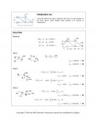
978-0073398242 Chapter 6 Solution Manual Part 25
PROBLEM 6.164 Using the method of joints, determine the force in each member of the truss shown. State whether each member is in tension or compression. SOLUTION Reactions: 0: 16 kN Cx M A 0: 9 kN yy F A […]
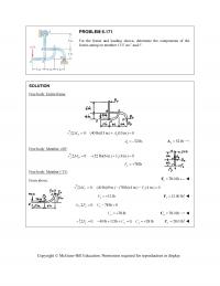
978-0073398242 Chapter 6 Solution Manual Part 26
PROBLEM 6.171 For the frame and loading shown, determine the components of the forces acting on member CFE at C and F. SOLUTION Free body: Entire frame: 0: (40 lb)(13 in.) (10 in.) 0 Dx MA 52 lb, […]
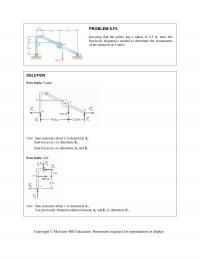
978-0073398242 Chapter 6 Solution Manual Part 27
PROBLEM 6.F4 Knowing that the pulley has a radius of 0.5 m, draw the free-body diagram(s) needed to determine the components of the reactions at A and E. SOLUTION Free body: Frame Note: Sum moments about E to determine A […]
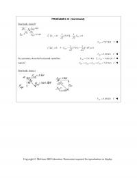
978-0073398242 Chapter 6 Solution Manual Part 3
PROBLEM 6.10 (Continued) Free body: Joint B: 11 0: 7.07 0 22 yBD FF 7.07 kN BD FT 11 0: 5 (7.07) 7.07 0 22 xBA FF 5.00 kN BA FC […]
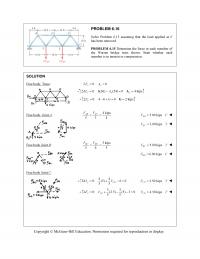
978-0073398242 Chapter 6 Solution Manual Part 4
PROBLEM 6.16 Solve Problem 6.15 assuming that the load applied at E has been removed. PROBLEM 6.15 Determine the force in each member of the Warren bridge truss shown. State whether each member is in tension or compression. SOLUTION Free […]
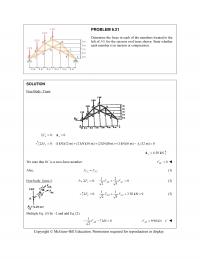
978-0073398242 Chapter 6 Solution Manual Part 5
PROBLEM 6.21 Determine the force in each of the members located to the left of FG for the scissors roof truss shown. State whether each member is in tension or compression. SOLUTION Free Body: Truss: 0: 0 xx F A […]
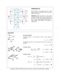
978-0073398242 Chapter 6 Solution Manual Part 6
PROBLEM 6.26 Solve Problem 6.24 assuming that the cables hanging from the right side of the tower have fallen to the ground. PROBLEM 6.24 The portion of truss shown represents the upper part of a power transmission line tower. For […]
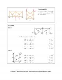
978-0073398242 Chapter 6 Solution Manual Part 7
PROBLEM 6.33 For the given loading, determine the zero-force members in each of the two trusses shown. SOLUTION Truss (a): Note: Reaction at F is vertical (0). x F Joint :G 0,F 0 DG F Joint :D 0,F 0 […]
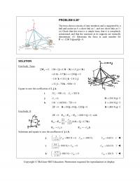
978-0073398242 Chapter 6 Solution Manual Part 8
PROBLEM 6.39* The truss shown consists of nine members and is supported by a ball and socket at B, a short link at C, and two short links at D. (a) Check that this truss is a simple truss, that […]
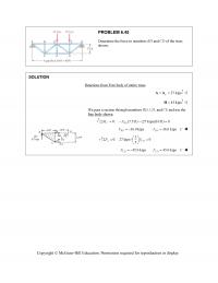
978-0073398242 Chapter 6 Solution Manual Part 9
PROBLEM 6.45 Determine the force in members BD and CD of the truss shown. SOLUTION Reactions from Free body of entire truss: 27 kips y AA 45 kipsH We pass a section through members BD, CD, and CE […]
978-0073398242 Chapter 7 Solution Manual Part 1
CHAPTER 7 PROBLEM 7.1 Determine the internal forces (axial force, shearing force, and bending moment) at Point J of the structure indicated. Frame and loading of Problem 6.76. SOLUTION From Problem 6.76: 720 lb x =C 140 lb y =C […]
978-0073398242 Chapter 7 Solution Manual Part 10
PROBLEM 7.59 (Continued) We set 2 2 22 1 11 111 | | | |: 2 82 282 AC M M wa wL wLa wa wL wLa= −=− +=− 22 0.25 0a La L+− = 22 22 max 11 ( […]
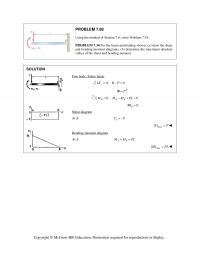
978-0073398242 Chapter 7 Solution Manual Part 11
PROBLEM 7.68 Using the method of Section 7.6, solve Problem 7.34. PROBLEM 7.34 For the beam and loading shown, (a) draw the shear and bending–moment diagrams, (b) determine the maximum absolute values of the shear and bending moment. SOLUTION Free […]
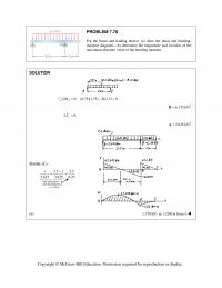
978-0073398242 Chapter 7 Solution Manual Part 12
PROBLEM 7.78 For the beam and loading shown, (a) draw the shear and bending– moment diagrams, (b) determine the magnitude and location of the maximum absolute value of the bending moment. SOLUTION 0: (8.75)(1.75) (2.5) 0 A MBΣ= − = […]
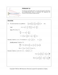
978-0073398242 Chapter 7 Solution Manual Part 13
PROBLEM 7.87 For the beam and loading shown, (a) write the equations of the shear and bending–moment curves, (b) determine the magnitude and location of the maximum bending moment. SOLUTION (a) We check that beam is in equilibrium ( ) […]
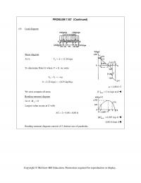
978-0073398242 Chapter 7 Solution Manual Part 14
PROBLEM 7.92* (Continued) (b) Load diagram Shear diagram At A: 2.26 kips A VA = = + To determine Point G where 0,V= we write GC VV w µ −=− 0 (1.22 kips) (0.25 kip/ft) µ −=− 4.88 ft µ […]
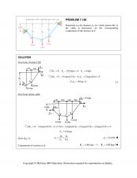
978-0073398242 Chapter 7 Solution Manual Part 15
PROBLEM 7.100 Determine (a) the distance dC for which portion BC of the cable is horizontal, (b) the corresponding components of the reaction at E. SOLUTION Free body: Portion CDE 0: 2(2 kips) 0 4 kips yy y FE EΣ= […]
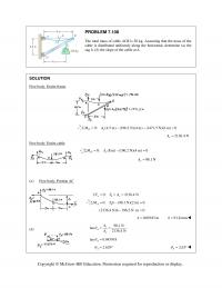
978-0073398242 Chapter 7 Solution Manual Part 16
PROBLEM 7.108 The total mass of cable ACB is 20 kg. Assuming that the mass of the cable is distributed uniformly along the horizontal, determine (a) the sag h, (b) the slope of the cable at A. SOLUTION Free body: […]
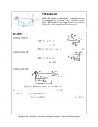
978-0073398242 Chapter 7 Solution Manual Part 17
PROBLEM 7.116 Cable ACB supports a load uniformly distributed along the horizontal as shown. The lowest Point C is located 9 m to the right of A. Determine (a) the vertical distance a, (b) the length of the cable, (c) […]
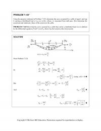
978-0073398242 Chapter 7 Solution Manual Part 18
PROBLEM 7.125* Using the property indicated in Problem 7.124, determine the curve assumed by a cable of span L and sag h carrying a distributed load w=w0 cos ( π x/L), where x is measured from mid–span. Also determine the […]
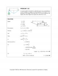
978-0073398242 Chapter 7 Solution Manual Part 19
PROBLEM 7.135 A counterweight D is attached to a cable that passes over a small pulley at A and is attached to a support at B. Knowing that L= 45 ft and h= 15 ft, determine (a) the length of […]
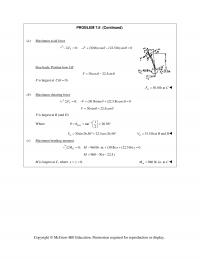
978-0073398242 Chapter 7 Solution Manual Part 2
PROBLEM 7.8 (Continued) (a) Maximum axial force 0: (30 lb)cos (22.5 lb)sin 0 V FF θθ Σ = −+ − = Free body: Portion bow CK 30cos 22.5sinF θθ = − F is largest at ( 0)C θ = 30.0 […]
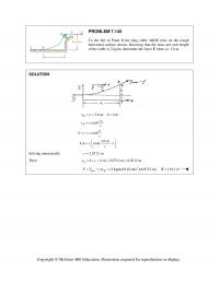
978-0073398242 Chapter 7 Solution Manual Part 20
PROBLEM 7.145 To the left of Point B the long cable ABDE rests on the rough horizontal surface shown. Knowing that the mass per unit length of the cable is 2 kg/m, determine the force F when a= 3.6 m. […]
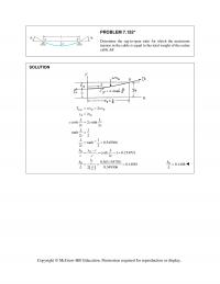
978-0073398242 Chapter 7 Solution Manual Part 21
PROBLEM 7.152* Determine the sag–to–span ratio for which the maximum tension in the cable is equal to the total weight of the entire cable AB. SOLUTION ( ) max 1 2 2 2 cosh 2 sinh 22 1 tanh 22 […]
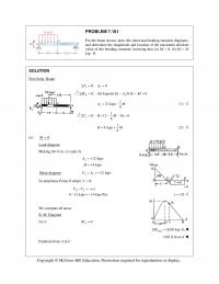
978-0073398242 Chapter 7 Solution Manual Part 22
PROBLEM 7.161 For the beam shown, draw the shear and bending–moment diagrams, and determine the magnitude and location of the maximum absolute value of the bending moment, knowing that (a) M = 0, (b) M = 24 kip ∙ ft. […]
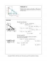
978-0073398242 Chapter 7 Solution Manual Part 3
PROBLEM 7.16 Knowing that the radius of each pulley is 200 mm and neglecting friction, determine the internal forces at Point K of the frame shown. SOLUTION Free body: frame and pulleys 0: (1.8 m) (360 N)(0.2 m) (360 N)(2.6 […]
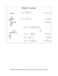
978-0073398242 Chapter 7 Solution Manual Part 4
PROBLEM 7.21 (Continued) 5 14 J 7 Copyright © McGraw–Hill Education. Permission required for reproduction or display. FBD AJ: 4 10 0: 0 53 x P FVΣ= −= 8 3 P =V 3 10 0: 0 53 […]
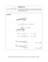
978-0073398242 Chapter 7 Solution Manual Part 5
PROBLEM 7.30 For the beam and loading shown, (a) draw the shear and bending- moment diagrams, (b) determine the maximum absolute values of the shear and bending moment. SOLUTION 2 00 11 1 22 2 xx wx w x w […]
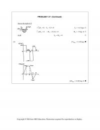
978-0073398242 Chapter 7 Solution Manual Part 6
PROBLEM 7.37 (Continued) max Copyright © McGraw–Hill Education. Permission required for reproduction or display. Just to the right of E: 4 0: 4.5 0 y FVΣ= − = 44.5 kipsV= + 44 0: (4.5)2 0MM Σ= − − = […]
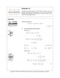
978-0073398242 Chapter 7 Solution Manual Part 7
PROBLEM 7.43 Assuming the upward reaction of the ground on beam AB to be uniformly distributed and knowing that P =wa, (a) draw the shear and bending-moment diagrams, (b) determine the maximum absolute values of the shear and bending moment. […]
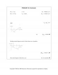
978-0073398242 Chapter 7 Solution Manual Part 8
PROBLEM 7.48 (Continued) Copyright © McGraw–Hill Education. Permission required for reproduction or display. For 3m:x= 0,V= 9.00 kN mM=−⋅ For 4.5 m:x= 6 kN, D V= + 4.50 kN m D M=−⋅ At B: 0 BB VM= = […]
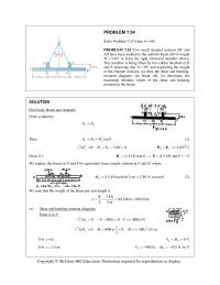
978-0073398242 Chapter 7 Solution Manual Part 9
PROBLEM 7.54 Solve Problem 7.53 when 60 . θ = ° PROBLEM 7.53 Two small channel sections DF and EH have been welded to the uniform beam AB of weight W 3 kN= to form the rigid structural member shown. […]
978-0073398242 Chapter 8 Solution Manual Part 1
CHAPTER 8 PROBLEM 8.1 Determine whether the block shown is in equilibrium and find the magnitude and direction of the friction force whenP 150 N. SOLUTION Assume equilibrium: 0: (500 N)sin 20 (150 N) cos 20 0 x FF […]
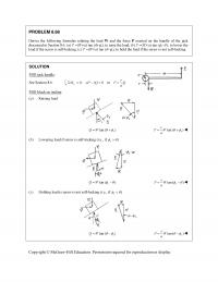
978-0073398242 Chapter 8 Solution Manual Part 10
PROBLEM 8.68 Derive the following formulas relating the load W and the force P exerted on the handle of the jack discussed in Section 8.6. (a) P (Wr/a) tan ( s ), to raise the load; (b) […]
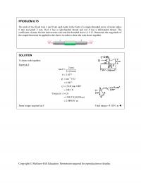
978-0073398242 Chapter 8 Solution Manual Part 11
PROBLEM 8.75 The ends of two fixed rods A and B are each made in the form of a single-threaded screw of mean radius 6 mm and pitch 2 mm. Rod A has a right-handed thread and rod B has […]
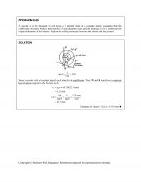
978-0073398242 Chapter 8 Solution Manual Part 12
Copyright © McGraw-Hill Education. Permission required for reproduction or display. PROBLEM 8.85 A scooter is to be designed to roll down a 2 percent slope at a constant speed. Assuming that the coefficient of kinetic friction between the 25-mm-diameter axles […]
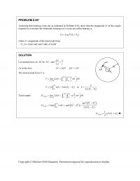
978-0073398242 Chapter 8 Solution Manual Part 13
Copyright © McGraw-Hill Education. Permission required for reproduction or display. PROBLEM 8.95* Assuming that bearings wear out as indicated in Problem 8.94, show that the magnitude M of the couple required to overcome the frictional resistance of a worn-out collar […]
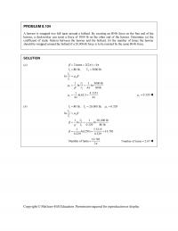
978-0073398242 Chapter 8 Solution Manual Part 14
Copyright © McGraw-Hill Education. Permission required for reproduction or display. PROBLEM 8.104 A hawser is wrapped two full turns around a bollard. By exerting an 80-lb force on the free end of the hawser, a dockworker can resist a force […]
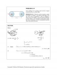
978-0073398242 Chapter 8 Solution Manual Part 15
PROBLEM 8.114 Solve Problem 8.113 assuming that the belt is looped around the pulleys in a figure eight. PROBLEM 8.113 A flat belt is used to transmit a couple from pulley A to pulley B. The radius of each pulley […]
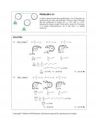
978-0073398242 Chapter 8 Solution Manual Part 16
PROBLEM 8.121 A cable is placed around three parallel pipes. Two of the pipes are fixed and do not rotate; the third pipe is slowly rotated. Knowing that the coefficients of friction are 0.25 s and 0.20, k […]
978-0073398242 Chapter 8 Solution Manual Part 17
PROBLEM 8.127 (Continued) Eq. (3): 17.5056 ln 4.9742 rad 2 1.3225 4.9742 s 0.2659 Eq. (4): sin 75 7.5056 cos 75 0.96953 7.2468 s 0.1333 We choose the larger […]
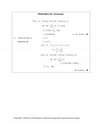
978-0073398242 Chapter 8 Solution Manual Part 18
PROBLEM 8.136 (Continued) 0: (32 in.) (12 in.) (24 in.) 0 AB MPWN 8 3 6 0 0.25 0.3 P PW P W tip ( 0.25 OK)PWP 0.25(120 lb)P or 30.0 lb P (c) […]
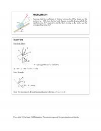
978-0073398242 Chapter 8 Solution Manual Part 19
PROBLEM 8.F1 Knowing that the coefficient of friction between the 25-kg block and the incline is s = 0.25, draw the free-body diagram needed to determine both the smallest value of P required to start the block moving up […]
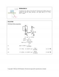
978-0073398242 Chapter 8 Solution Manual Part 2
PROBLEM 8.8 Considering only values of less than 90, determine the smallest value of required to start the block moving to the right when (a) 75 lb,W (b) 100 lb.W SOLUTION FBD block (Motion impending): 1 tan […]
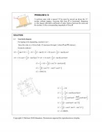
978-0073398242 Chapter 8 Solution Manual Part 3
PROBLEM 8.15 A uniform crate with a massof 30 kg must be moved up along the 15° incline without tipping. Knowing that force P is horizontal, determine (a) the largest allowable coefficient of static friction between the crate and the […]
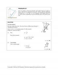
978-0073398242 Chapter 8 Solution Manual Part 4
PROBLEM 8.24 End A of a slender, uniform rod of length L and weight W bears on a surface as shown, while end B is supported by a cord BC. Knowing that the coefficients of friction are 0.40 s […]
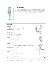
978-0073398242 Chapter 8 Solution Manual Part 5
PROBLEM 8.33 A pipe of diameter 60 mm is gripped by the stillson wrench shown. Portions AB and DE of the wrench are rigidly attached to each other, and portion CF is connected by a pin at D. If the […]
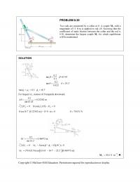
978-0073398242 Chapter 8 Solution Manual Part 6
PROBLEM 8.39 Two rods are connected by a collar at B. A couple M A with a magnitude of 15 N·m is applied to rod AB. Knowing that the coefficient of static friction between the collar and the rod is […]
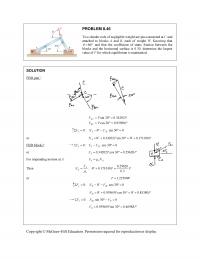
978-0073398242 Chapter 8 Solution Manual Part 7
PROBLEM 8.46 Two slender rods of negligible weight are pin-connected at C and attached to blocks A and B, each of weight W. Knowing that 80 and that the coefficient of static friction between the blocks and […]
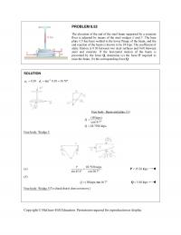
978-0073398242 Chapter 8 Solution Manual Part 8
PROBLEM 8.52 The elevation of the end of the steel beam supported by a concrete floor is adjusted by means of the steel wedges E and F. The base plate CD has been welded to the lower flange of the […]
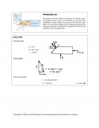
978-0073398242 Chapter 8 Solution Manual Part 9
PROBLEM 8.60 The spring of the door latch has a constant of 1.8 lb/in. and in the position shown exerts a 0.6-lb force on the bolt. The coefficient of static friction between the bolt and the strike plate is 0.40; […]
978-0073398242 Chapter 9 Solution Manual Part 1
CHAPTER 9 PROBLEM 9.1 Determine by direct integration the moment of inertia of the shaded area with respect to the y axis. SOLUTION At 2 0, : 0xybbka 2 b ka then 2 2 ; b […]
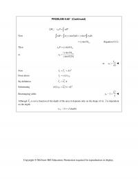
978-0073398242 Chapter 9 Solution Manual Part 10
PROBLEM 9.66* (Continued) : yP M xP xdP Now (sin) sin x dP x y dA xydA (sin) x y I (Equation 9.12) Then (sin) Pxy x PI or (sin) […]
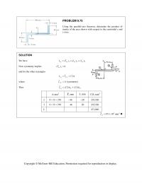
978-0073398242 Chapter 9 Solution Manual Part 11
PROBLEM 9.75 Using the parallel-axis theorem, determine the product of inertia of the area shown with respect to the centroidal x and y axes. SOLUTION We have 123 ()() () xy xy xy xy II I I Now symmetry implies […]
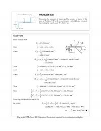
978-0073398242 Chapter 9 Solution Manual Part 12
PROBLEM 9.82 Determine the moments of inertia and the product of inertia of the area of Problem 9.75 with respect to new centroidal axes obtained by rotating the x and y axes 45 clockwise. SOLUTION From Problem 9.75: 4 471,040 […]
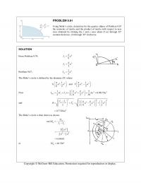
978-0073398242 Chapter 9 Solution Manual Part 13
PROBLEM 9.91 Using Mohr’s circle, determine for the quarter ellipse of Problem 9.67 the moments of inertia and the product of inertia with respect to new axes obtained by rotating the x and y axes about O (a) through 45 […]
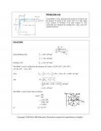
978-0073398242 Chapter 9 Solution Manual Part 14
PROBLEM 9.96 Using Mohr’s circle, determine the moments of inertia and the product of inertia of the L152 102 12.7-mm angle cross section of Problem 9.78 with respect to new centroidal axes obtained by rotating the x and y axes […]

978-0073398242 Chapter 9 Solution Manual Part 15
PROBLEM 9.101 Using Mohr’s circle, determine for the area indicated the orientation of the principal centroidal axes and the corresponding values of the moments of inertia. Area of Problem 9.74. SOLUTION From Problem 9.83: 4 0.390 in 1.09 in x […]
978-0073398242 Chapter 9 Solution Manual Part 16
PROBLEM 9.106* (Continued) ( b ) We have max,min ave 750 709.46IIR or 4 max 1459 inI and 4 min 40.5 inI From the Mohr’s circle it is seen that the a axis corresponds to max I […]
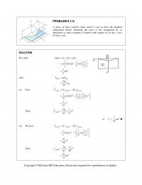
978-0073398242 Chapter 9 Solution Manual Part 17
PROBLEM 9.115 A piece of thin, uniform sheet metal is cut to form the machine component shown. Denoting the mass of the component by m , determine its mass moment of inertia with respect to ( a ) the x […]
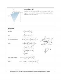
978-0073398242 Chapter 9 Solution Manual Part 18
PROBLEM 9.122 Determine by direct integration the mass moment of inertia with respect to the x axis of the tetrahedron shown, assuming that it has a uniform density and a mass m. SOLUTION We have 1 […]
978-0073398242 Chapter 9 Solution Manual Part 19
PROBLEM 9.127 (Continued) and 22 22 22 2 62 2 2 113 31 (479.96) (183.41) 848 82 11 1ft (769.80) 1 10 lb s /ft in 82 144 in AA I […]
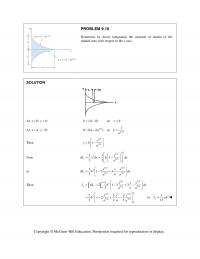
978-0073398242 Chapter 9 Solution Manual Part 2
PROBLEM 9.10 Determine by direct integration the moment of inertia of the shaded area with respect to the x axis. SOLUTION At 0, :xyb (1 0)bc or cb At ,0:xay 1/2 0(1 )bka 1/2 1 or ka Then 1/2 […]
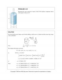
978-0073398242 Chapter 9 Solution Manual Part 20
PROBLEM 9.134 Determine the mass moment of inertia of the 0.9-lb machine component shown with respect to the axis AA. SOLUTION First note that the given shape can be formed adding a small cone to a cylinder and then removing […]
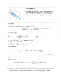
978-0073398242 Chapter 9 Solution Manual Part 21
PROBLEM 9.138 A section of sheet steel 0.03 in. thick is cut and bent into the sheet metal machine component shown. Determine the mass moment of inertia of the component with respect to each of the coordinate axes. (The specific […]
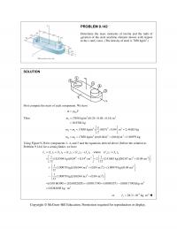
978-0073398242 Chapter 9 Solution Manual Part 22
PROBLEM 9.142 Determine the mass moments of inertia and the radii of gyration of the steel machine element shown with respect to the x and y axes. (The density of steel is 7850 kg/m 3 .) SOLUTION First compute the […]
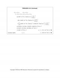
978-0073398242 Chapter 9 Solution Manual Part 23
PROBLEM 9.146 (Continued) 24 35 12345 2 32 2 () (), () () () () () () () 1 ft [(8.5857 10 lb s /ft)(16 in.) ] 12 in. yy yy yy y y y y II II II I […]
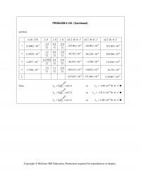
978-0073398242 Chapter 9 Solution Manual Part 24
PROBLEM 9.152 (Continued) and then 2 ,lb s /ftm ,ft x ,fty,ftz 2 ,lb ft smx y 2 ,lb ft smy z 2 ,lb ft smz x 1 3 31.0062 10 3.9 12 […]
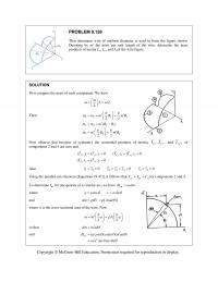
978-0073398242 Chapter 9 Solution Manual Part 25
PROBLEM 9.158 Thin aluminum wire of uniform diameter is used to form the figure shown. Denoting by m the mass per unit length of the wire, determine the mass products of inertia I xy , I yz , and I […]
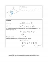
978-0073398242 Chapter 9 Solution Manual Part 26
PROBLEM 9.163 The homogeneous circular cone shown has a mass m. Determine the mass moment of inertia of the cone with respect to the line joining the origin O and Point A. SOLUTION First note that 222 39 (3) (3) […]
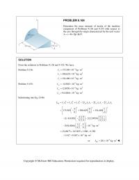
978-0073398242 Chapter 9 Solution Manual Part 27
PROBLEM 9.169 Determine the mass moment of inertia of the machine component of Problems 9.136 and 9.155 with respect to the axis through the origin characterized by the unit vector (4 8 )/9. λijk SOLUTION From the solutions to […]
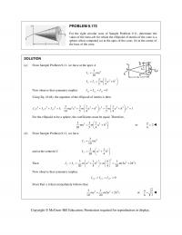
978-0073398242 Chapter 9 Solution Manual Part 28
PROBLEM 9.175 For the right circular cone of Sample Problem 9.11, determine the value of the ratio a/h for which the ellipsoid of inertia of the cone is a sphere when computed (a) at the apex of the cone, (b) […]
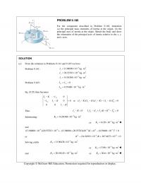
978-0073398242 Chapter 9 Solution Manual Part 29
PROBLEM 9.180 For the component described in Problem 9.165, determine (a) the principal mass moments of inertia at the origin, (b) the principal axes of inertia at the origin. Sketch the body and show the orientation of the principal axes […]
978-0073398242 Chapter 9 Solution Manual Part 3
PROBLEM 9.19 (Continued) Find: and xx Ik We have 33 21 333 3 11 12 (2) sin 33 3 2 8(2)sin 32 xh dI y y dx x a h x dx aa hxa x a a […]
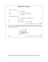
978-0073398242 Chapter 9 Solution Manual Part 30
PROBLEM 9.182* (Continued) Adding and solving for 3 () z 33 ( ) 0.707885( ) zx and then 33 3 ( ) [ 2.46156 1.5( 0.707885)]( ) 1.39973( ) yx x […]
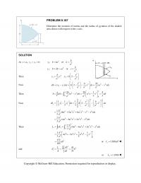
978-0073398242 Chapter 9 Solution Manual Part 31
PROBLEM 9.187 Determine the moment of inertia and the radius of gyration of the shaded area shown with respect to the x axis. SOLUTION At 11 2 ,: x ayyb 2 12 2 22 :or :2 or b ybka k […]
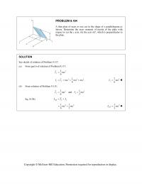
978-0073398242 Chapter 9 Solution Manual Part 32
PROBLEM 9.194 A thin plate of mass m was cut in the shape of a parallelogram as shown. Determine the mass moment of inertia of the plate with respect to (a) the y axis, (b) the axis AA, which is […]
978-0073398242 Chapter 9 Solution Manual Part 4
PROBLEM 9.24 (Continued) Now 44 2 3 16 3 4 64 Pxy JII r 44 31.15545 316 rr 4 or 1.155 P J r […]
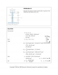
978-0073398242 Chapter 9 Solution Manual Part 5
PROBLEM 9.31 Determine the moment of inertia and the radius of gyration of the shaded area with respect to the x axis. SOLUTION First note that 123 2 2 2 [(24)(6) (8)(48) (48)(6)] mm (144 384 288) mm 816 mm […]
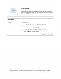
978-0073398242 Chapter 9 Solution Manual Part 6
PROBLEM 9.40 Knowing that the shaded area is equal to 6000 mm2 and that its moment of inertia with respect to AA is 18 106 mm4, determine its moment of inertia with respect to BB for d1 = 50 […]
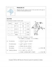
978-0073398242 Chapter 9 Solution Manual Part 7
PROBLEM 9.46 Determine the polar moment of inertia of the area shown with respect to (a) Point O, (b) the centroid of the area. SOLUTION Determination of centroid C of entire section: Section Area, in2 ,in.x 3 ,inxA 1 2 […]
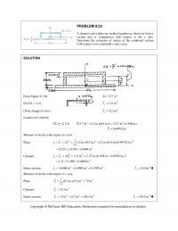
978-0073398242 Chapter 9 Solution Manual Part 8
PROBLEM 9.53 A channel and a plate are welded together as shown to form a section that is symmetrical with respect to the y axis. Determine the moments of inertia of the combined section with respect to its centroidal x […]
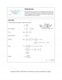
978-0073398242 Chapter 9 Solution Manual Part 9
PROBLEM 9.60* The panel shown forms the end of a trough that is filled with water to the line AA. Referring to section 9.2, determine the depth of the point of application of the resultant of the hydrostatic forces acting […]