PROBLEM 7.21 (Continued)
5 14
J
7
PROBLEM 7.22
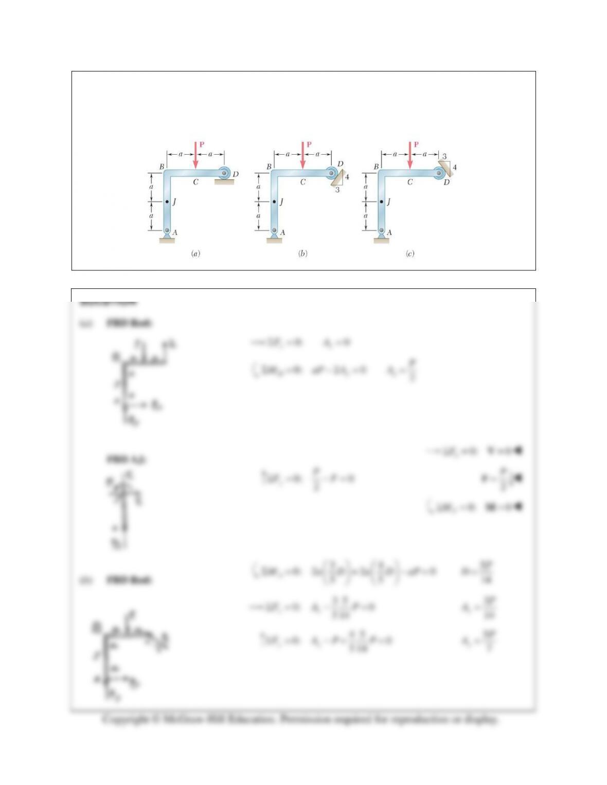
A force P is applied to a bent rod that is supported by a roller and a pin and bracket. For each of the three
cases shown, determine the internal forces at Point J.
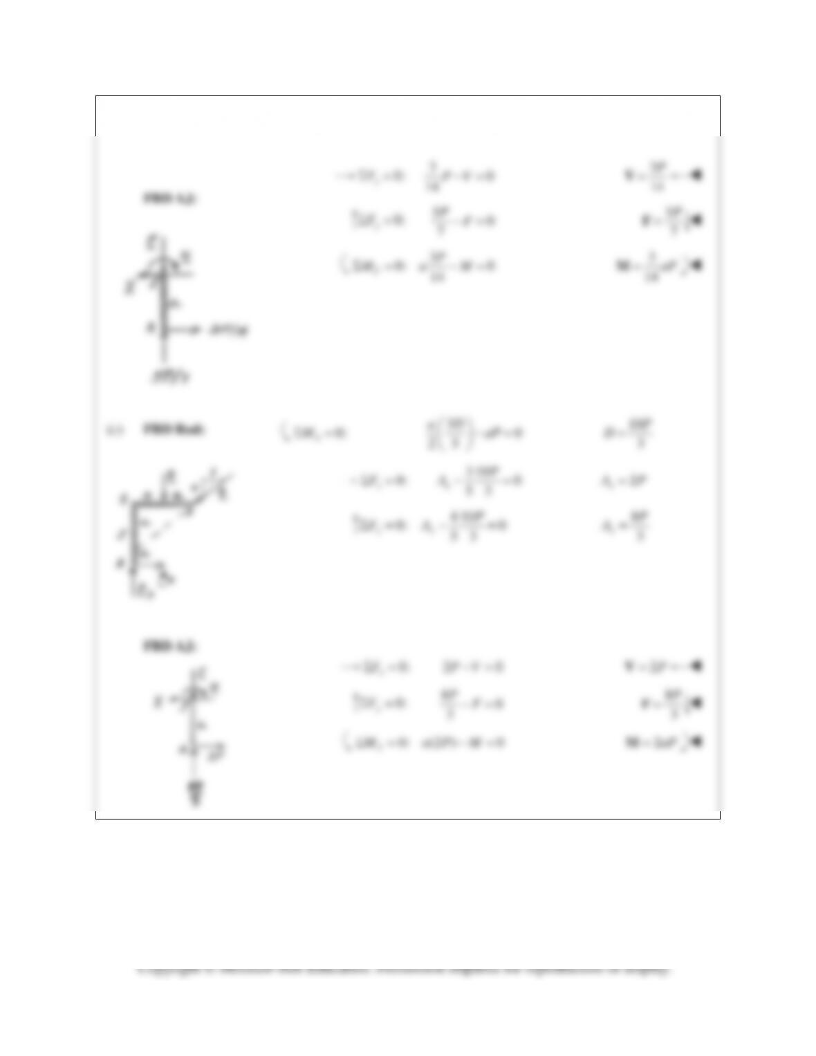
PROBLEM 7.22 (Continued)
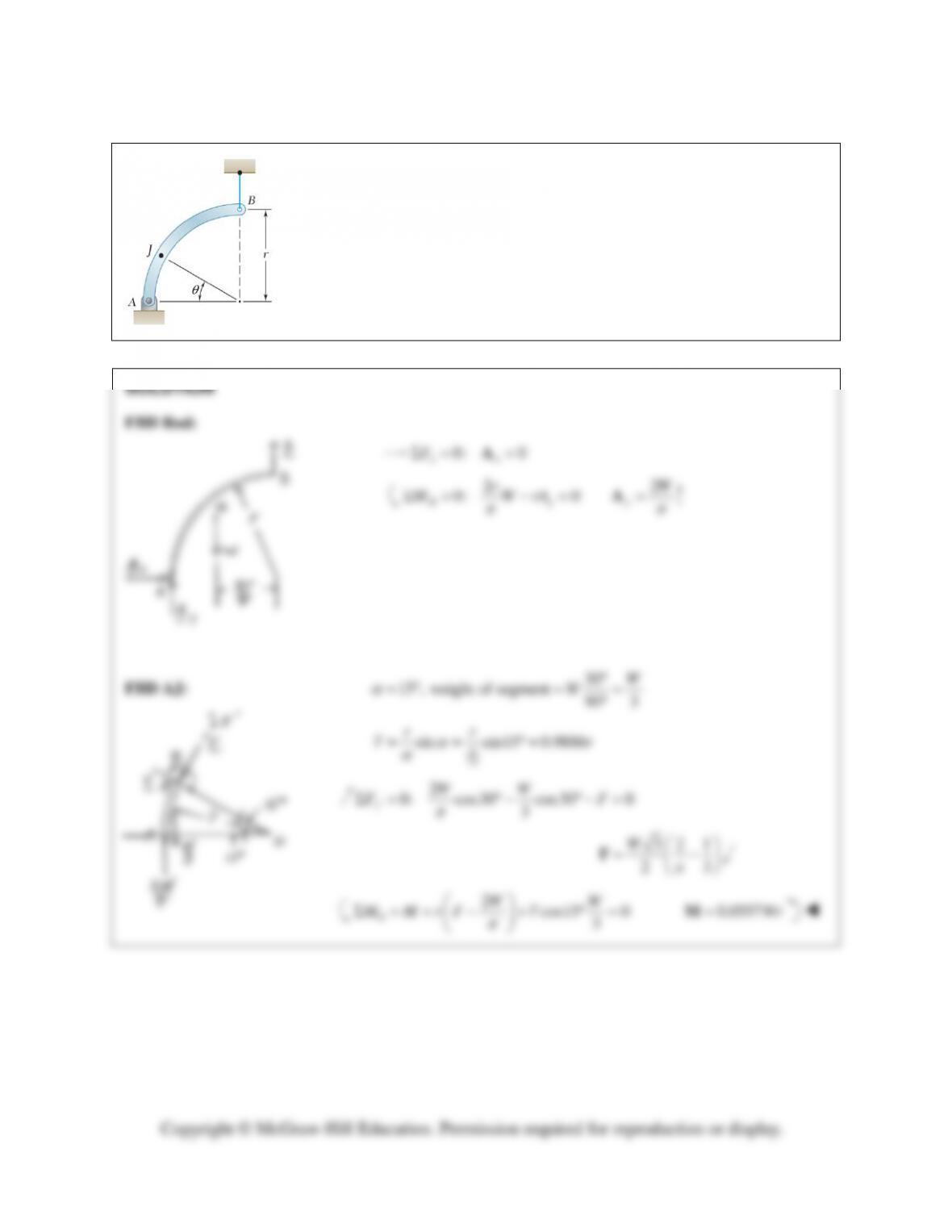
PROBLEM 7.23
A quarter–circular rod of weight W and uniform cross section is supported as
shown. Determine the bending moment at Point J when
θ
= 30°.
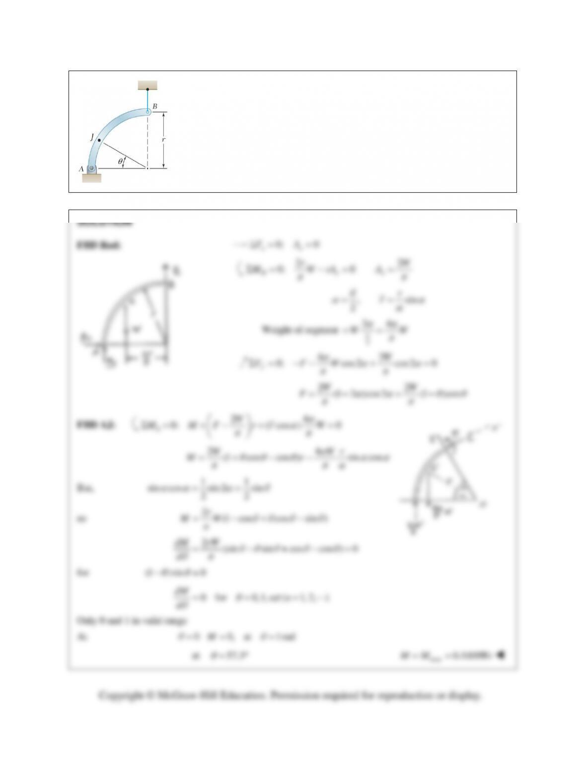
PROBLEM 7.24
For the rod of Problem 7.23, determine the magnitude and location of the
maximum bending moment.
PROBLEM 7.23 A quarter–circular rod of weight W and uniform cross section
is supported as shown. Determine the bending moment at Point J when
θ
= 30°.
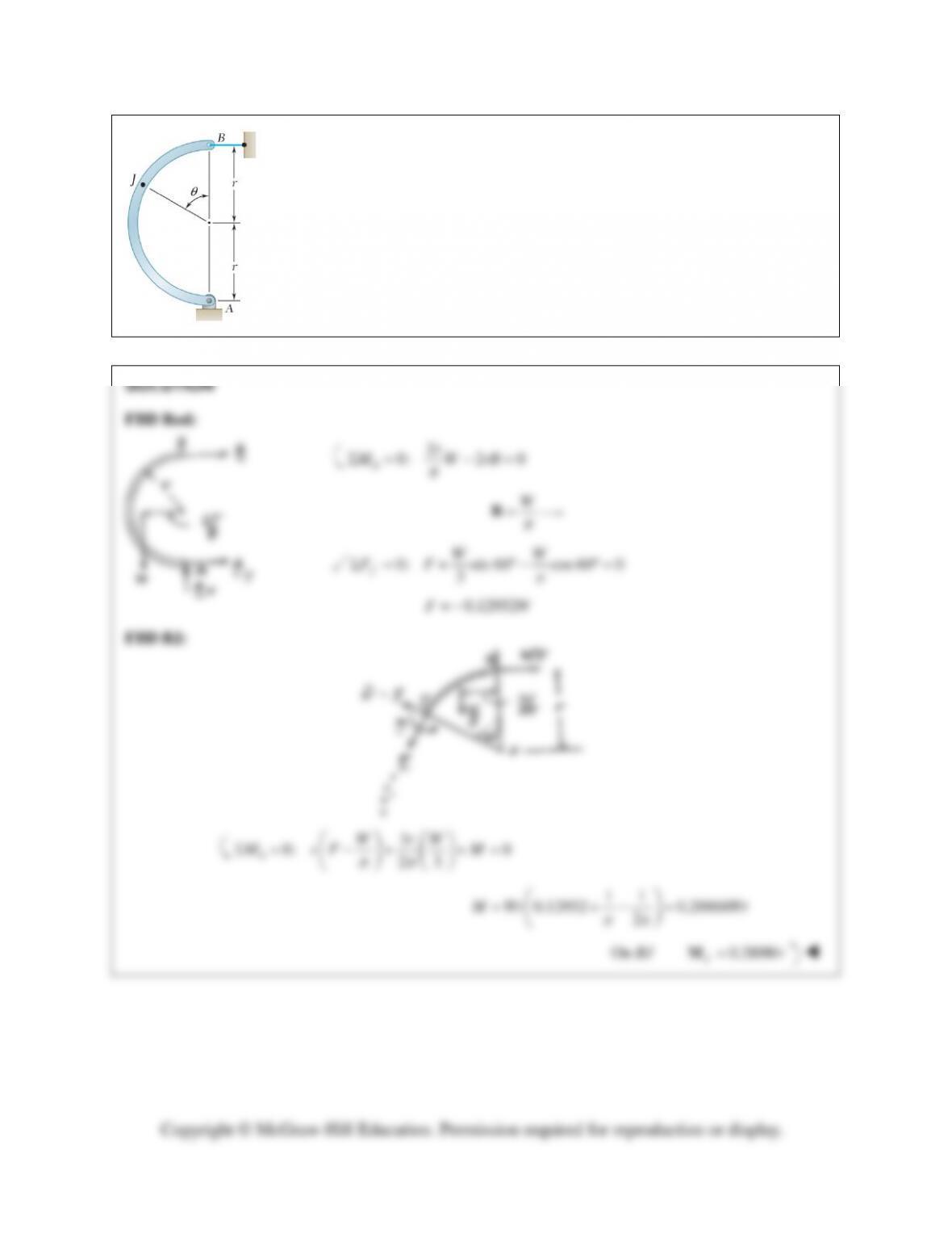
PROBLEM 7.25
A semicircular rod of weight W and uniform cross section is supported as shown.
Determine the bending moment at Point J when
θ
= 60°.
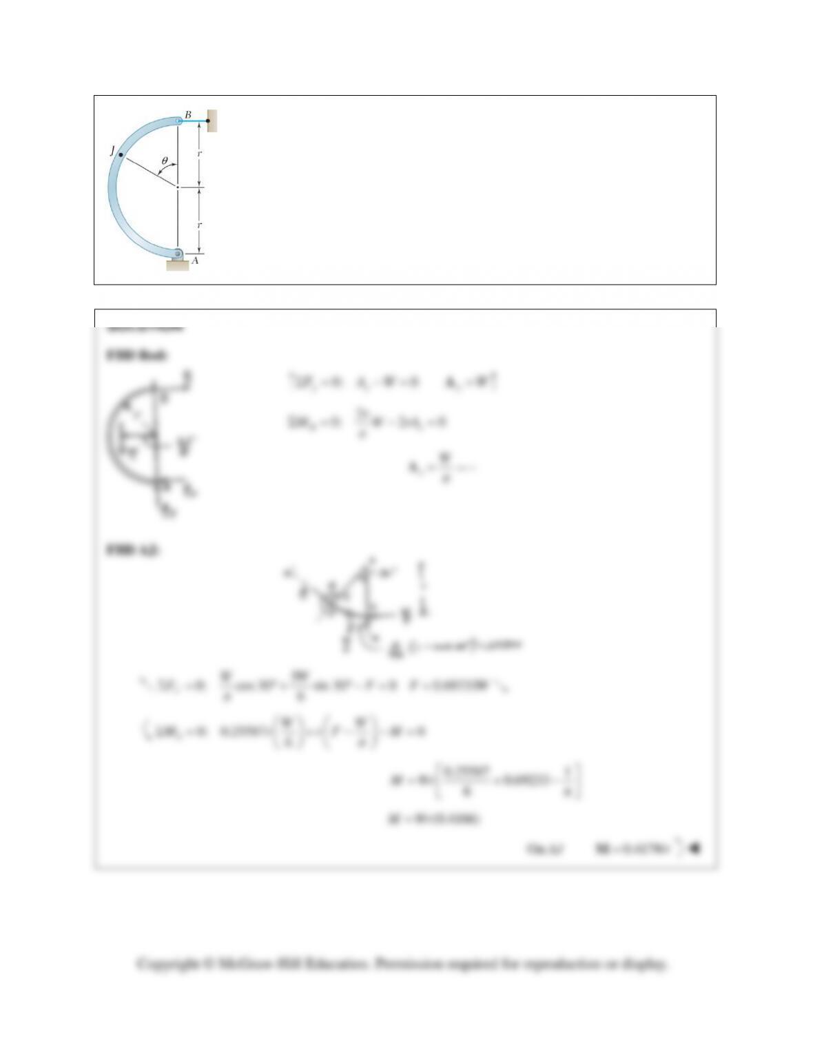
PROBLEM 7.26
A semicircular rod of weight W and uniform cross section is supported as shown.
Determine the bending moment at Point J when
θ
= 150°.

PROBLEM 7.27
A half section of pipe rests on a frictionless horizontal surface as shown. If
the half section of pipe has a mass of 9 kg and a diameter of 300 mm,
determine the bending moment at Point J when
θ
= 90°.
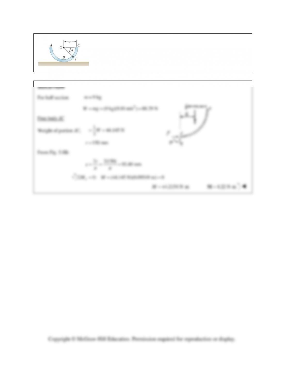
PROBLEM 7.28
A half section of pipe rests on a frictionless horizontal surface as shown. If
the half section of pipe has a mass of 9 kg and a diameter of 300 mm,
determine the bending moment at point J when
θ
= 90°.
PROBLEM 7.29
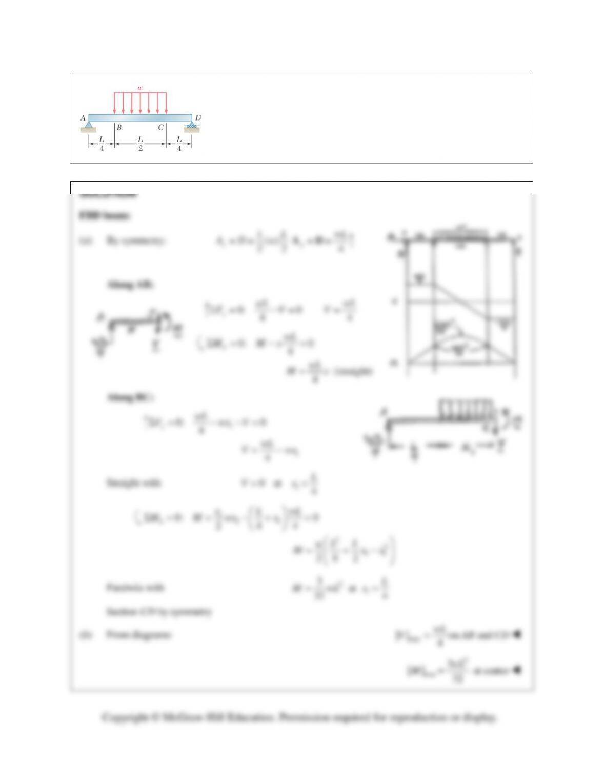
For the beam and loading shown, (a) draw the shear and bending-
moment diagrams, (b) determine the maximum absolute values of the
shear and bending moment.