PROBLEM 18.16
For the assembly of Prob. 18.15, determine (
a
) the angular
momentum
B
H
of the assembly about point
B
, (
b
) the angle
formed by
B
H
and
BA
.
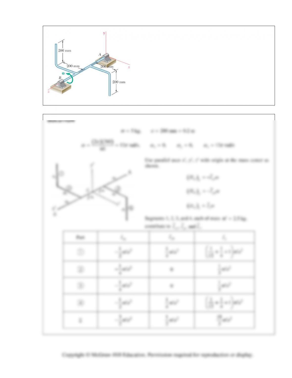
PROBLEM 18.15:
Two L-shaped arms, each of mass 5 kg, are
welded at the one-third points of the 600 mm shaft
AB
to form
the assembly shown. Knowing that the assembly rotates at the
constant rate of 360 rpm, determine (
a
) the angular momentum
A
H
of the assembly about point
A
, (
b
) the angle formed by
A
H
and
AB
.
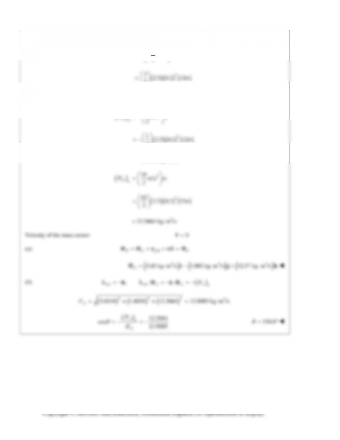
PROBLEM 18.16 (Continued)
2
3
Gx
Hma
2
32.5 0.2 12
2
2
5.6549 kg m /s
2
1
2
2
1.8850 kg m /s
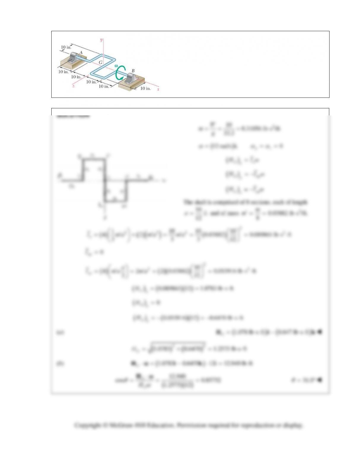
PROBLEM 18.17
A 10-lb rod of uniform cross section is used to form the shaft
shown. Knowing that the shaft rotates with a constant angular
velocity ω of magnitude 12 rad/s, determine (a) the angular
momentum G
H of the shaft about its mass center G, (b) the
angle formed by G
H and the axis AB.
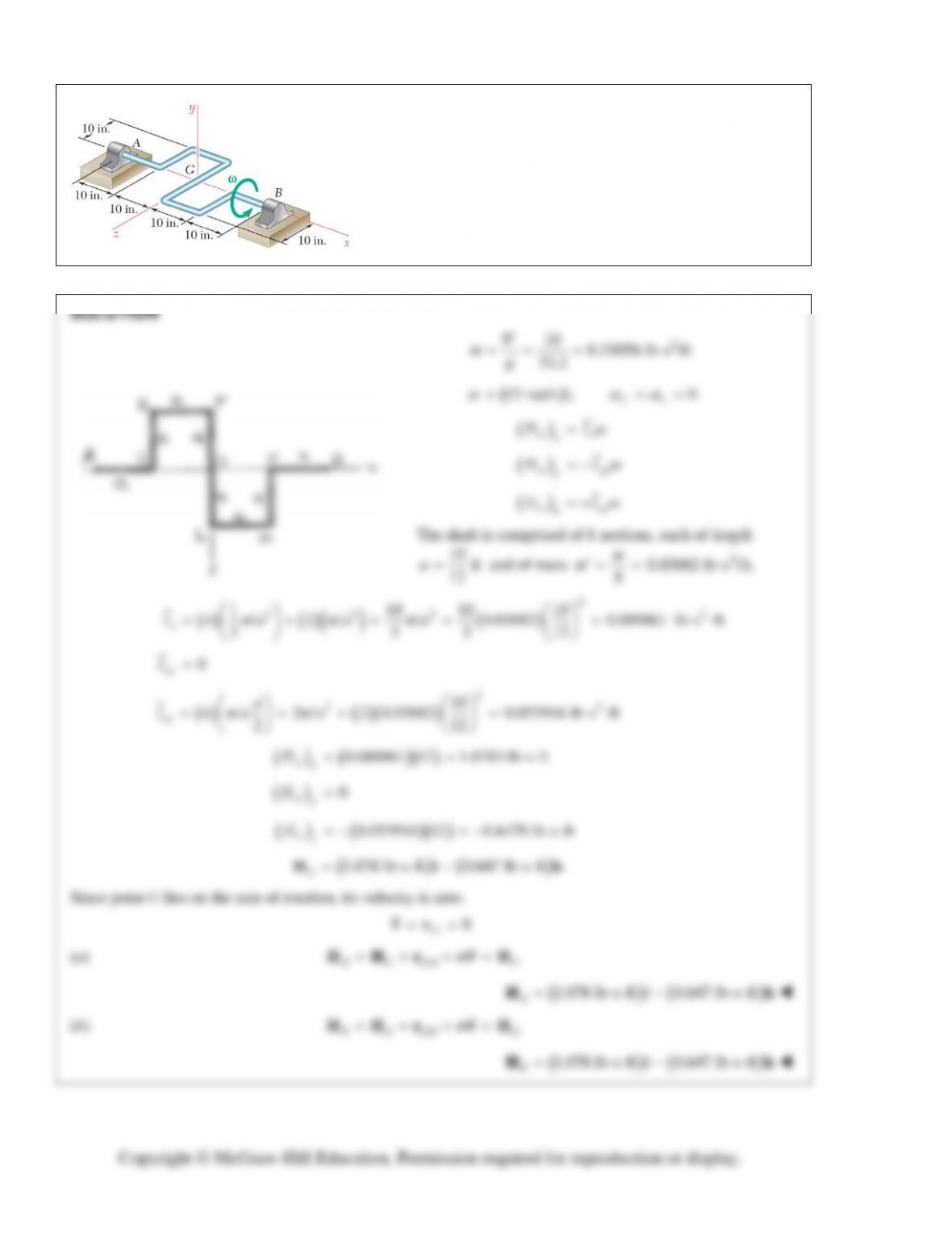
PROBLEM 18.18
Determine the angular momentum of the shaft of Prob. 18.17
about (a) point A, (b) point B.
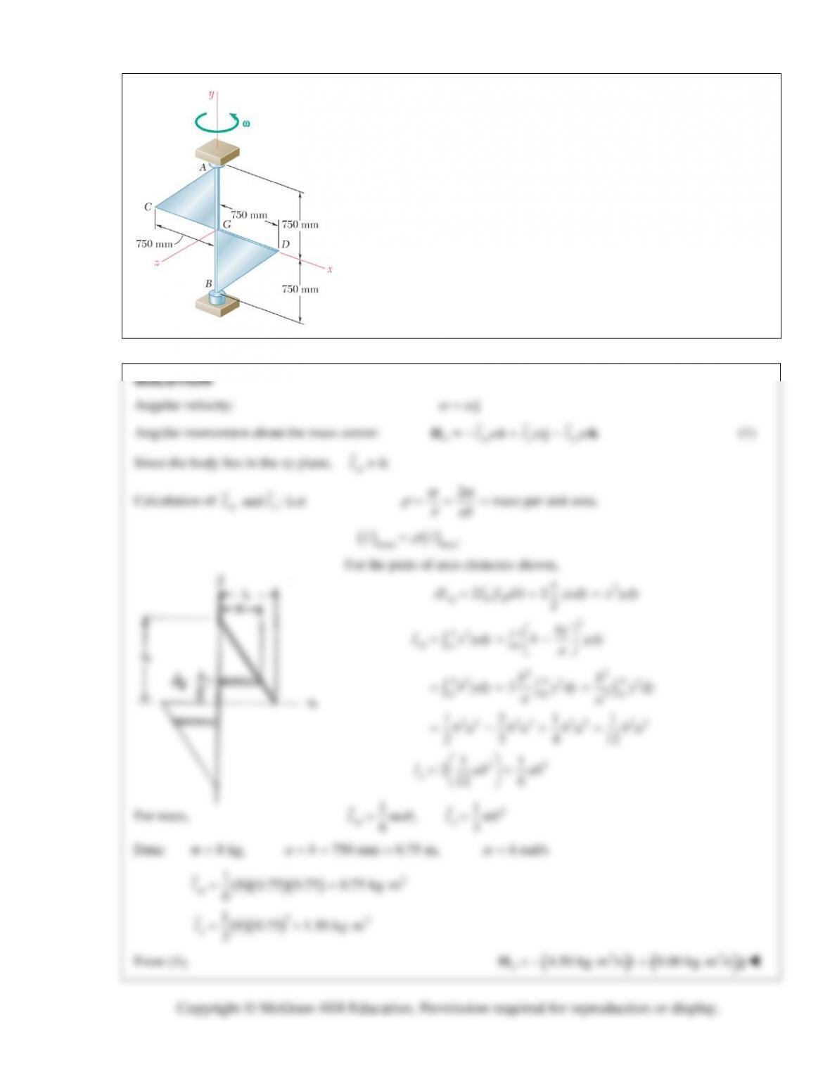
PROBLEM 18.19
Two triangular plates, each of mass 8 kg, are welded to a vertical shaft
AB
. Knowing that the system rotates at the constant rate
ω
= 6 rad/s,
determine its angular momentum about
G
.
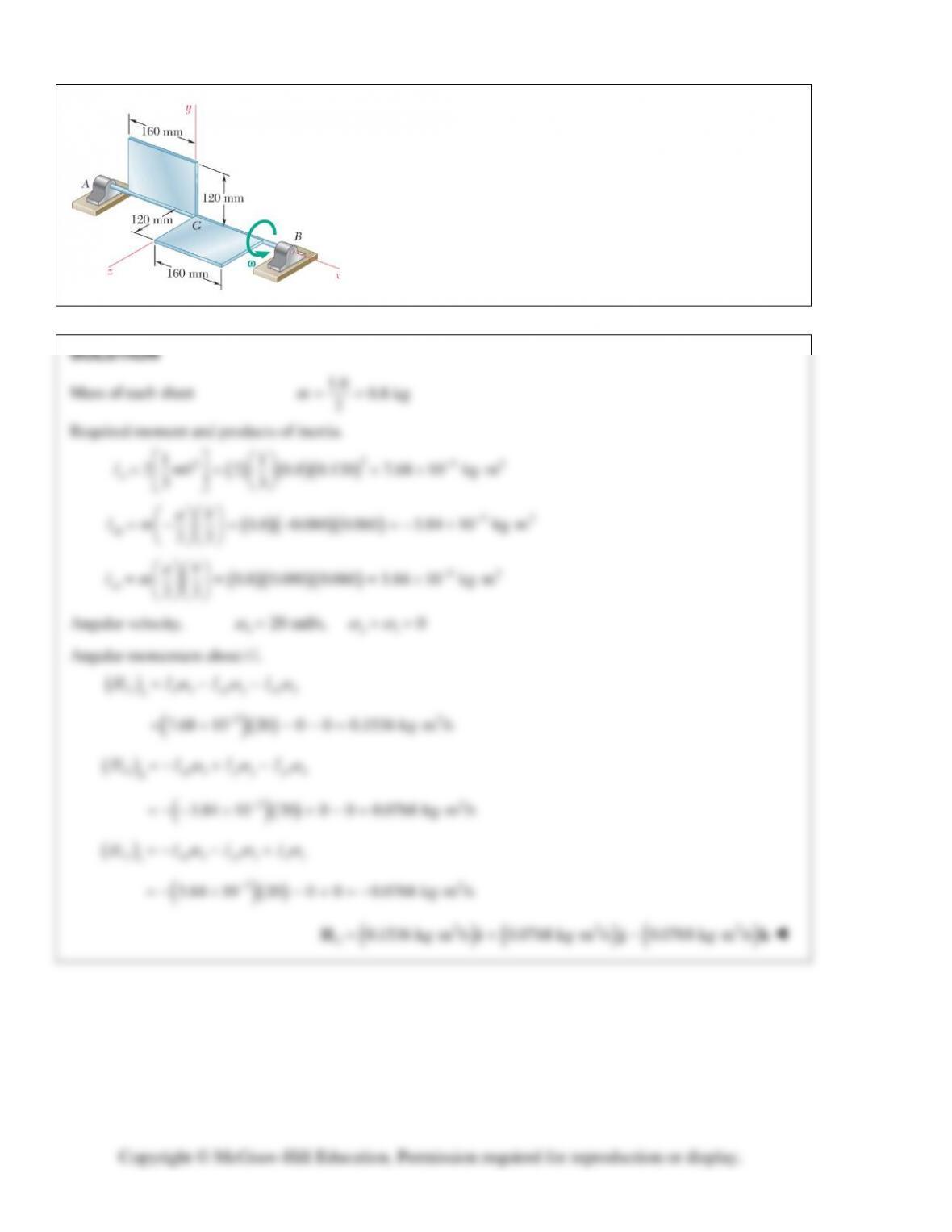
PROBLEM 18.20
The assembly shown consists of two pieces of sheet aluminum of
uniform thickness and total mass 1.6 kg welded to a light axle
supported by bearings A and B. Knowing that the assembly
rotates with an angular velocity of constant magnitude
ω = 20 rad/s, determine the angular momentum G
H of the
assembly about point G.
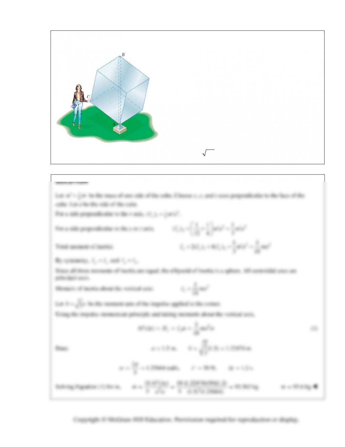
PROBLEM 18.21
One of the sculptures displayed on a university campus consists
of a hollow cube made of six aluminum sheets, each
1.5 1.5 m,
welded together and reinforced with internal braces
of negligible weight. The cube is mounted on a fixed base at A
and can rotate freely about its vertical diagonal AB. As she
passes by this display on the way to a class in mechanics, an
engineering student grabs corner C of the cube and pushes it
for 1.2 s in a direction perpendicular to the plane ABC with an
average force of 50 N. Having observed that it takes 5 s for the
cube to complete one full revolution, she flips out her
calculator and proceeds to determine the mass of the cube.
What is the result of her calculation? (Hint: The perpendicular
distance from the diagonal joining two vertices of a cube to any
of its other six vertices can be obtained by multiplying the side
of the cube by 2/3.)
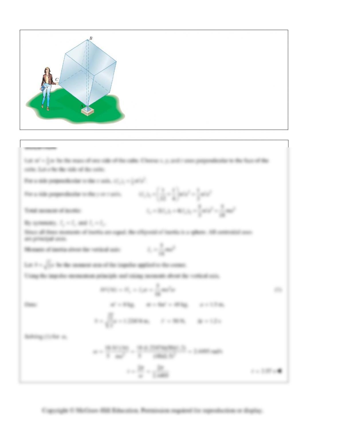
PROBLEM 18.22
If the aluminum cube of Problem 18.21 were replaced by a
cube of the same size, made of six plywood sheets with mass
8 kg each, how long would it take for that cube to complete one
full revolution if the student pushed its corner C in the same
way that she pushed the corner of the aluminum cube?
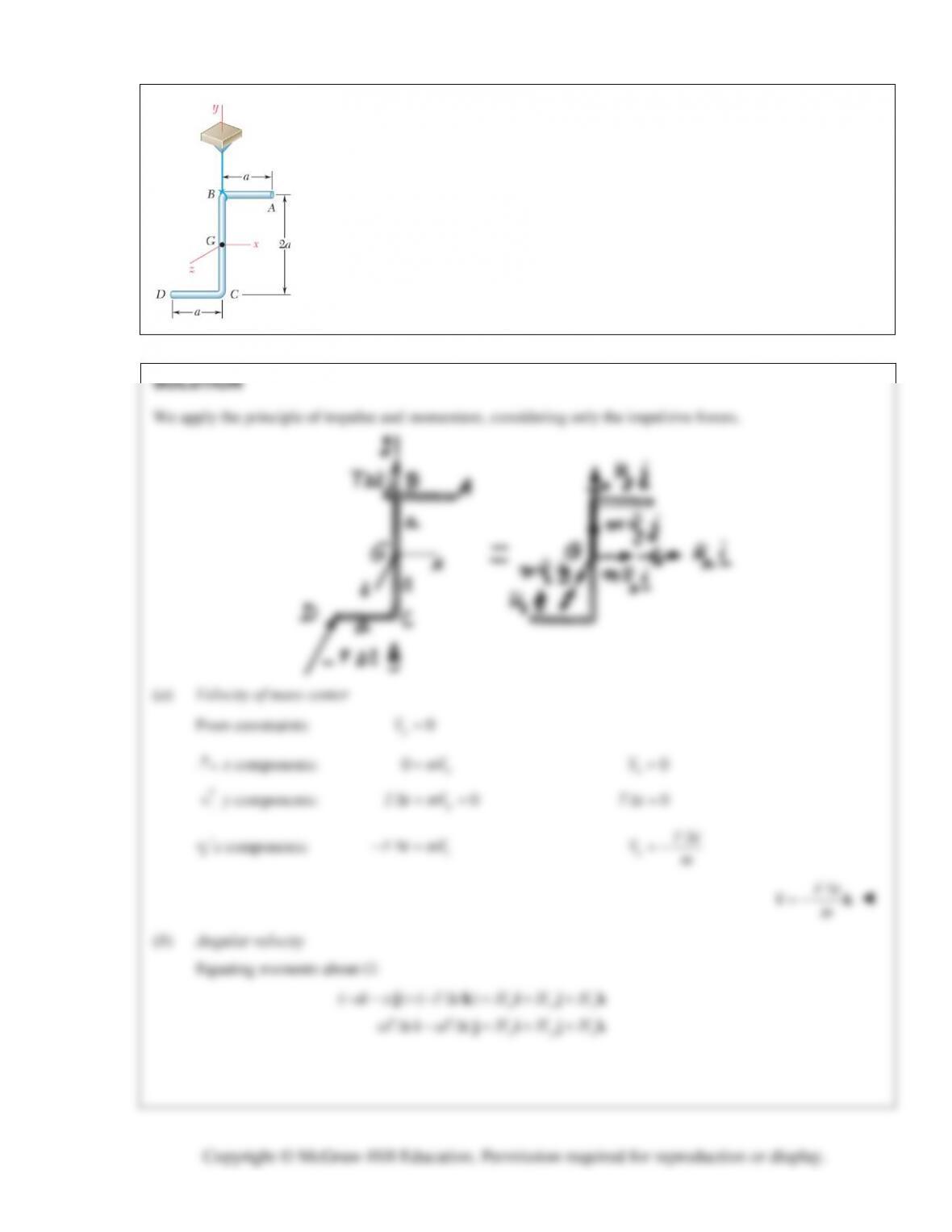
PROBLEM 18.23
A uniform rod of total mass
m
is bent into the shape shown and is suspended by a
wire attached at
B
. The bent rod is hit at
D
in a direction perpendicular to the plane
containing the rod (in the negative
z
direction). Denoting the corresponding impulse
by
F
t
, determine (
a
) the velocity of the mass center of the rod, (
b
) the angular
velocity of the rod.
PROBLEM 18.23 (Continued)
Thus: ,,0
xy z
HaFtH aFtH
(1)
To determine angular velocity, we shall use Eqs. (18.7).
12 2 4 4 3
(2)
11
m
xz yz
We substitute the expressions (1) through (5) into Eqs. (18.7):
210
xy