
PROBLEM 7.48 (Continued)
PROBLEM 7.49
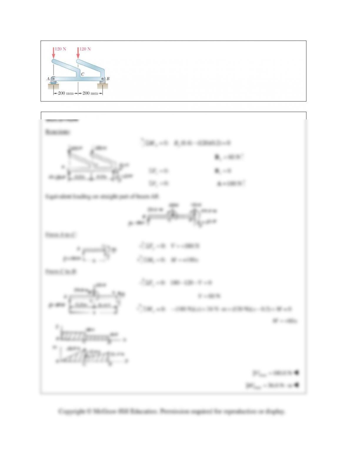
Draw the shear and bending–moment diagrams for the beam AB, and
determine the maximum absolute values of the shear and bending moment.
PROBLEM 7.50
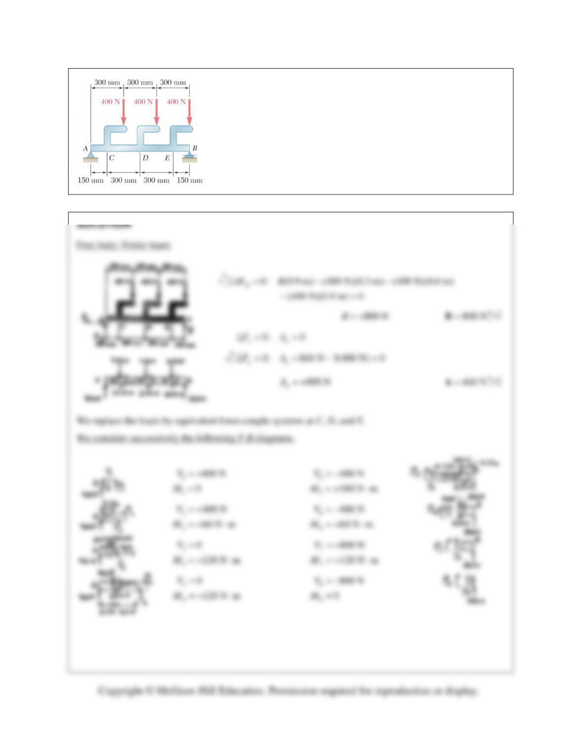
Draw the shear and bending–moment diagrams for the beam AB, and
determine the maximum absolute values of the shear and bending
moment.
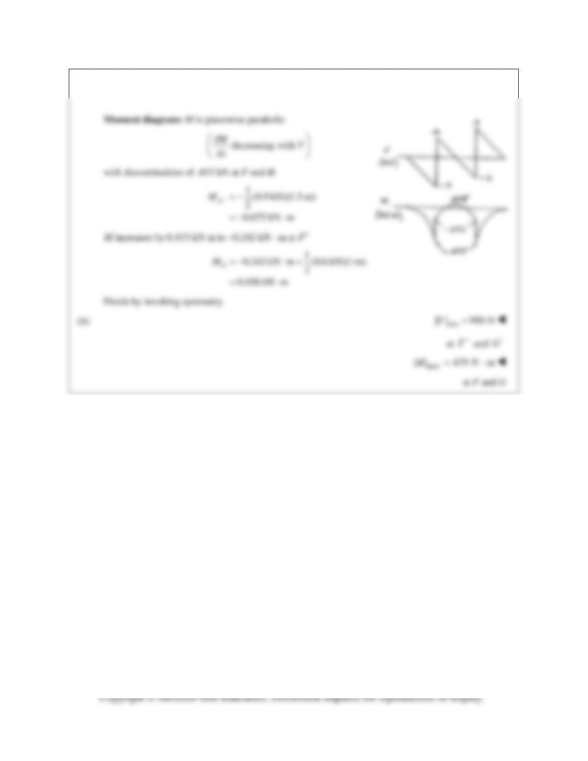
PROBLEM 7.50 (Continued)
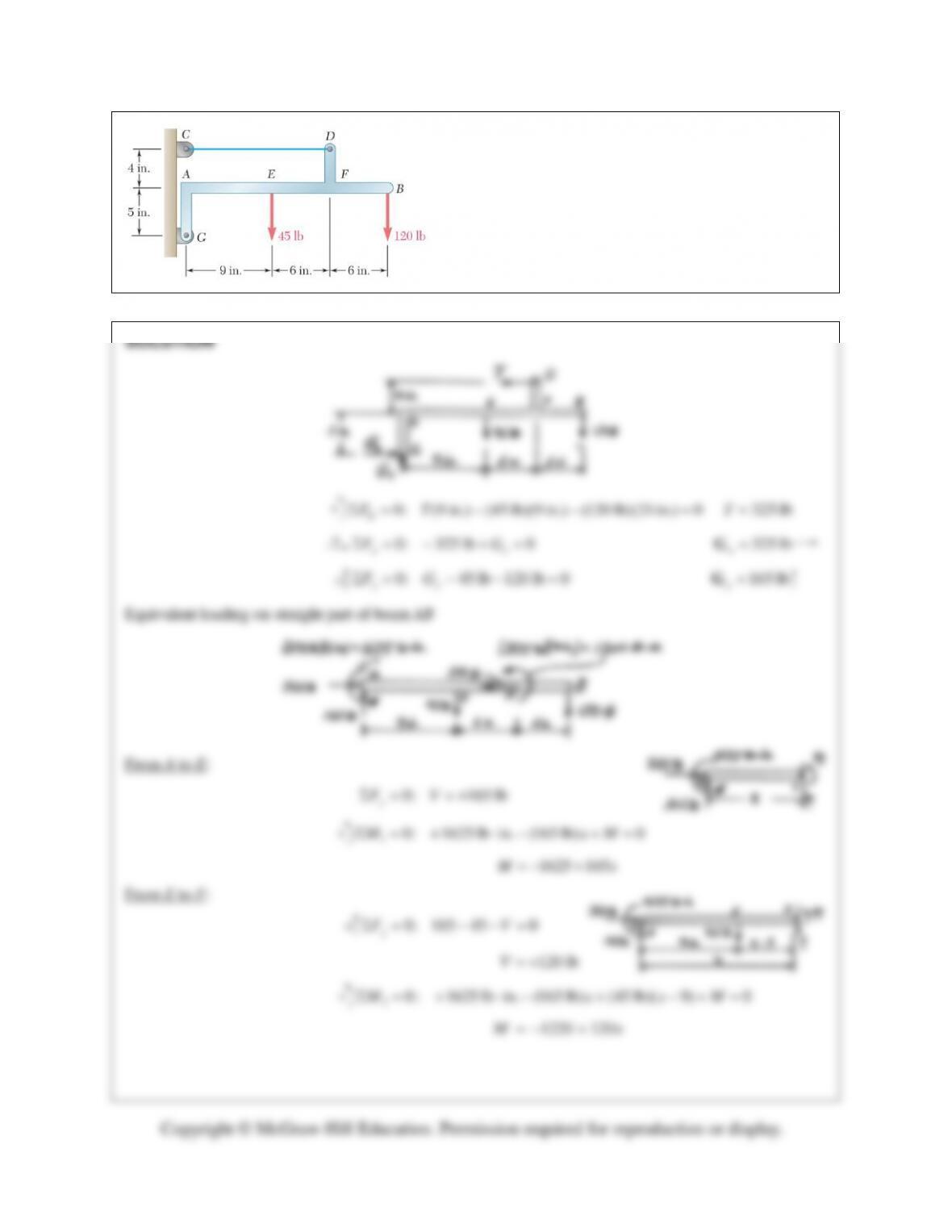
PROBLEM 7.51
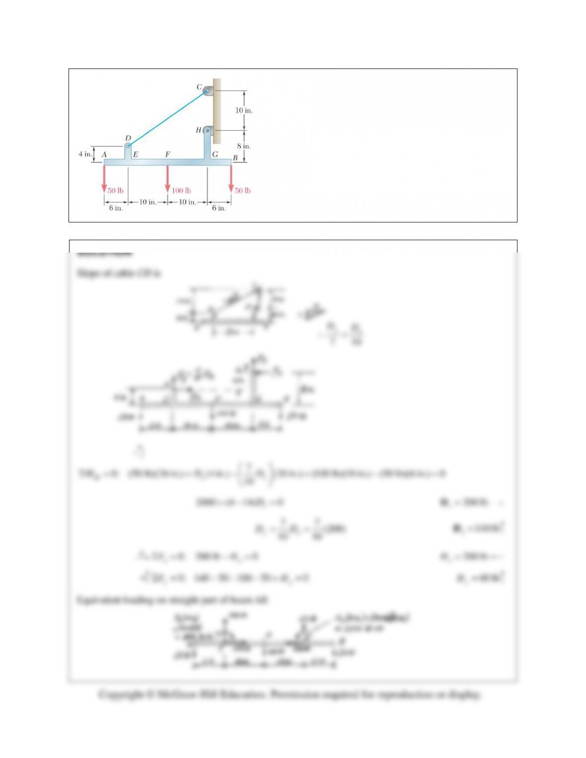
Draw the shear and bending–moment diagrams for the
beam AB, and determine the maximum absolute values of
the shear and bending moment.
PROBLEM 7.51 (Continued)
max max
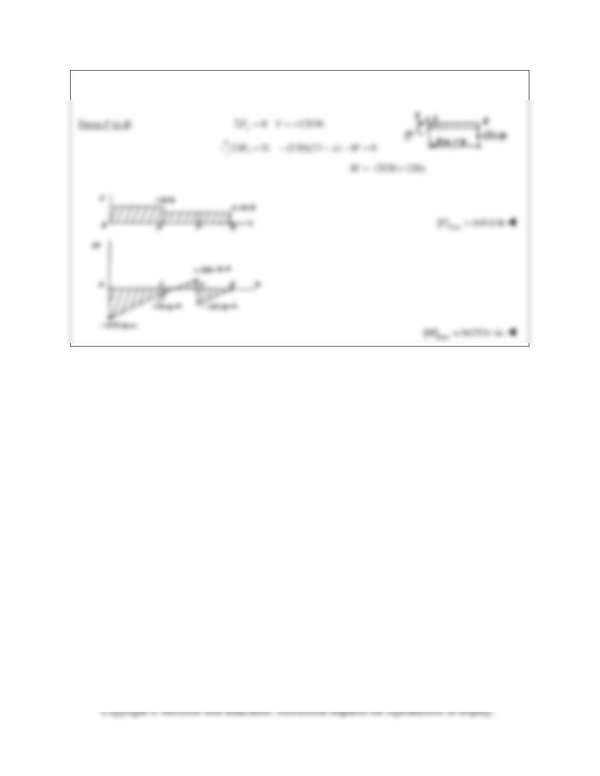
PROBLEM 7.52
Draw the shear and bending–moment diagrams for the
beam AB, and determine the maximum absolute values
of the shear and bending moment.
PROBLEM 7.52 (Continued)
max
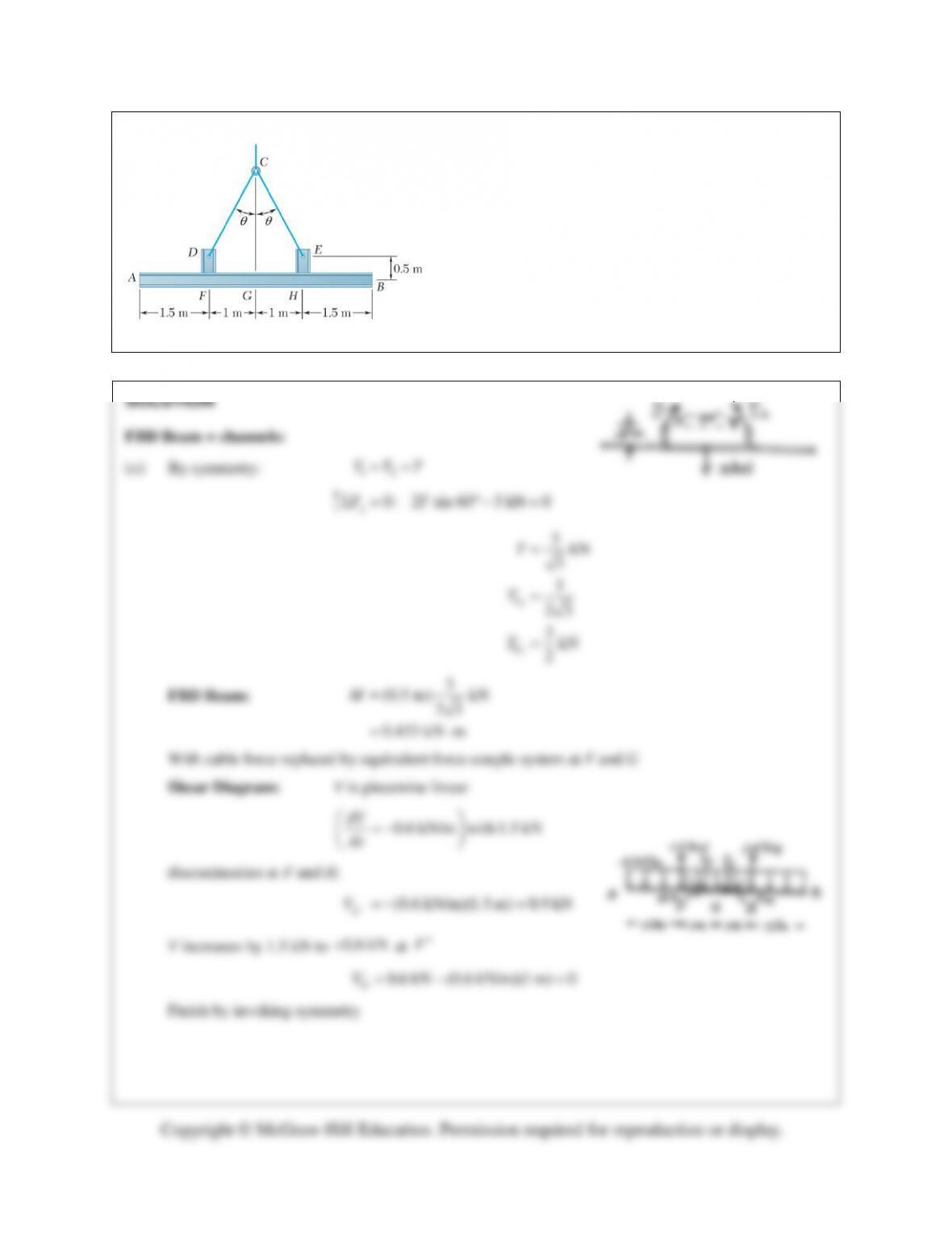
PROBLEM 7.53
Two small channel sections DF and EH have been
welded to the uniform beam AB of weight W= 3 kN to
form the rigid structural member shown. This member is
being lifted by two cables attached at D and E. Knowing
that
θ
= 30° and neglecting the weight of the channel
sections, (a) draw the shear and bending–moment
diagrams for beam AB, (b) determine the maximum
absolute values of the shear and bending moment in the
beam.
PROBLEM 7.53 (Continued)